OST iConverter XG+ User manual

iConverter®XG+
User Manual
38 Tesla, Irvine, CA 92618 USA
Phone: (949) 250-6510; Fax: (949) 250-6514
General and Copyright Notice
This publication is protected by U.S. and international copyright laws. All rights
reserved. The whole or any part of this publication may not be reproduced, stored
in a retrieval system, translated, transcribed, or transmitted, in any form, or by
any means, manual, electric, electronic, electromagnetic, mechanical, chemical,
optical or otherwise, without prior explicit written permission of Omnitron Systems
Technology, Inc.
The following trademarks are owned by Omnitron Systems Technology, Inc.:
FlexPointTM, FlexSwitchTM, HybridNID®, iConverter®, miConverterTM, NetOutlook®,
OmniLight®, OmniConverter®, RuggedNet®, Omnitron Systems Technology, Inc.TM,
OSTTM and the Omnitron logo.
All other company or product names may be trademarks of their respective owners.
The information contained in this publication is subject to change without notice.
Omnitron Systems Technology, Inc. is not responsible for any inadvertent errors.
Warranty
This network product and the included AC/DC power adapter are warranted to the
original purchaser (Buyer) against defects in material and workmanship for a period
of two (2) years from the date of shipment. The warranty for the network product
can be extended to lifetime by registering the product at www.omnitron-systems.
com/support within ninety (90) days from the date of shipment. During the warranty
period, Omnitron will, at its option, repair or replace a product which is proven to be
defective with the same product or with a product with at least the same functionality.
For warranty service, the product must be sent to an Omnitron designated facility,
at Buyer’s expense. Omnitron will pay the shipping charge to return the product
to Buyer’s designated US address using Omnitron’s standard shipping method.
Limitation of Warranty
The foregoing warranty shall not apply to product malfunctions resulting from
improper or inadequate use and/or maintenance of the equipment by Buyer, Buyer-
supplied equipment, Buyer-supplied interfacing, unauthorized modications or
tampering with equipment (including removal of equipment cover by personnel not
specically authorized and certied by Omnitron), or misuse, or operating outside
the environmental specication of the product (including but not limited to voltage,
ambient temperature, radiation, unusual dust, etc.), or improper site preparation
or maintenance.
No other warranty is expressed or implied. Omnitron specically disclaims the implied
warranties of merchantability and tness for any particular purpose.
The remedies provided herein are the Buyer’s sole and exclusive remedies. Omnitron
shall not be liable for any direct, indirect, special, incidental, or consequential
damages, whether based on contract, tort, or any legal theory.
Environmental Notices
The equipment covered by this manual must be disposed of or recycled in
accordance with the Waste Electrical and Electronic Equipment Directive (WEEE
Directive) of the European Community directive 2012/19/EU on waste electrical and
electronic equipment (WEEE) which, together with the RoHS Directive 2015/863/
Page 2

iConverter XG+
User Manual
Product Overview
Product update for rmware revision 1.1.4. Operational change to the self-diagnostic
circuit test.
The iConverter XG+ (8599R-xx) is a protocol-transparent ber media converter
with two pluggable transceiver ports supporting data rates from 6G to 11.32G and
supports the three Rs (regeneration, retiming and reshaping). The XG+ auto-detects
the speed of the installed transceiver.
The XG+ supports power level 1 and 2 SFP+ transceivers and power level 1, 2, 3
and 4 XFP transceivers. Specically, the module was designed to support power
level 3 and 4 transceivers as indicated in the table below. To support only the lower
level transceivers (1 and 2) use the XG (8599P-xx) module.
The XG+ plug-in modules support the configuration of programmable XFP
transceivers. To utilize this feature, the XG+ must be installed in a chassis with a
Management module. Access the Port Conguration menu on the XG+ to congure
the programmable XFP transceiver.
The XG+ requires management module rmware of version 5.2.30 or higher
and NetOutlook SNMP Software of version 5.3.16 or higher to fully recognize
and utilize the capabilities of the 8599R.
Port 2 - SFP+ Port 2 - XFP
Power
Level 1
Power
Level 2
Power
Level 3 or 4
Power
Level 1
Power
Level 2
Power
Level 3 or 4
Port 1
SFP+
Power
Level 1 x 8599R-00 x x x 8599R-01
Power
Level 2 8599R-00 8599R-00 x 8599R-01 8599R-01 8599R-01
Power
Level 3 or 4 x x x x x x
Port 1
XFP
Power
Level 1 x x x x x 8599R-11
Power
Level 2 x x x x x 8599R-11
Power
Level 3 or 4 x x x 8599R-11 8599R-11 8599R-11
MSA compliant SFP+ and XFP transceivers can be installed in the XG+. Refer to the
transceiver manufacturer’s data sheet for the maximum operating case temperature
to avoid any damage to the transceiver due to overheating issue. Installation in
chassis with high airow fans may help reduce any overheating issue.
Page 4
EU, for electrical and electronic equipment sold in the EU after July 2019. Such
disposal must follow national legislation for IT and Telecommunication equipment
in accordance with the WEEE directive: (a) Do not dispose waste equipment with
unsorted municipal and household waste. (b) Collect equipment waste separately.
(c) Return equipment using collection method agreed with Omnitron.
The equipment is marked with the WEEE symbol shown to indicate that it
must be collected separately from other types of waste. In case of small items the
symbol may be printed only on the packaging or in the user manual. If you have
questions regarding the correct disposal of equipment go to www.omniton-systems.
Safety Warnings and Cautions
ATTENTION: Observe precautions for handling electrostatic discharge
sensitive devices.
WARNING: Potential damage to equipment and personal injury.
WARNING: Risk of electrical shock.
Customer Support Information
Phone: (949) 250-6510
Fax: (949) 250-6514
Address: Omnitron Systems Technology, Inc.
38 Tesla
Irvine, CA 92618, USA
Email: [email protected]
URL: www.omnitron-systems.com
Page 3

SW2 - P2 LOOPBACK “P2-LB”
When this DIP-switch is in the LEFT/DOWN position (factory default), P2 loopback
is disabled. When this DIP-switch is in the RIGHT/UP “P2-LB” position, loopback
is enabled on P2. When enabled, all data received on P2 is transmitted out P2 and
all data received on P1 is dropped. No data is transmitted on P1 when loopback
is enabled on P2.
For XFP models, the loopback feature is dependent on the capability of the
installed XFP. XFPs with XFI Line-side Loopback feature is required.
SW3, SW4 - Reserved
These switches are reserved and must be in the LEFT/DOWN default position.
DIP-SWITCH BANK 2
The function of DIP-switch Bank 2 is outlined in the table below.
SW1 SW2 SW3 SW4 Function
DOWN DOWN DOWN DOWN Link Segment (default)
UP DOWN DOWN DOWN Asymmetrical Link Propagate P1 to P2
DOWN UP DOWN DOWN Asymmetrical Link Propagate P2 to P1
UP UP DOWN DOWN Dual Asymmetrical Link Propagate
DOWN DOWN UP DOWN Remote Fault Detect for P1 and P2
UP DOWN UP DOWN RFD + Asymmetrical LP P1 to P2
DOWN UP UP DOWN RFD + Asymmetrical LP P2 to P1
UP UP UP DOWN RFD + Dual Asymmetrical LP
DOWN DOWN DOWN UP Symmetrical Fault Detect (SFD)*
DOWN DOWN UP UP Self Diagnostic Circuit Test for Remote Module
UP UP UP UP Self Diagnostic Circuit Test for Local Module
DIP-switch BANK 2 Denitions
LINK MODES
These four DIP-switches congure the different link modes available on the XG+. It is
recommended to have link modes set to Link Segment (default setting - all DOWN)
during the initial installation. After the circuit has been tested and operational,
congure the module for the desired mode.
For detailed information on the operation of the different Link Modes, download the
application note “iConverter Link Modes” available at:
https://www.omnitron-systems.com/documentation/iconverter-product-
documentation/application-notes-and-other-documents
* SFD requires bookend conguration of two iConverter XG+s connected via Port 1.
SELF DIAGNOSTIC CIRCUIT TEST (SFP+ models only)
The self-diagnostic circuit test on the 8599-0x and 8599N-0x are not compatible
with the self-diagnostic circuit test on the 8599P-0x and 8599R-0x.
When two XG 8599P or XG+ 8599R converters are connected via Port 1 (Port 1 to
Port 1), a self diagnostic circuit test is supported. To initiate a self diagnostic circuit
test, both the local and remote module must be congured.
Page 6
Installation Procedure
1) Congure DIP-switches
2) Installing the Module
3) Apply Power
4) Connect Cables
5) Verify Operation
1) CONFIGURE DIP-SWITCHES
The location of the DIP-switches is shown below.
DIP-switch Locations
DIP-SWITCH BANK 1
The function of DIP-switch Bank 1 is outlined in the table below.
Switch LEFT/DOWN
(Default) RIGHT/UP
SW1 Normal P1 Loopback Enabled
SW2 Normal P2 Loopback Enabled
SW3, SW4 Reserved Reserved
DIP-switch BANK 1 Denitions
The XG+ supports port loopback. The SFP+/SFP+ XG+ supports loopback on each
individual port or simultaneous loopback on Port 1 and Port 2. The SFP+/XFP and
the XFP/XFP XG+ supports loopback on each individual port and does not support
simultaneous loopback.
In all cases, both transceivers must be installed in the XG+ for the loopback
feature to operate.
SW1 - P1 LOOPBACK “P1-LB”
When this DIP-switch is in the LEFT/DOWN position (factory default), Port 1 (P1)
loopback is disabled. When this DIP-switch is in the RIGHT/UP “P1-LB” position,
loopback is enabled on P1. When enabled, all data received on P1 is transmitted
out P1 and all data received on Port 2 (P2) is dropped. No data is transmitted on
P2 when loopback is enabled on P1.
For XFP models, the loopback feature is dependent on the capability of the
installed XFP. XFPs with XFI Line-side Loopback feature is required.
Page 5

Carefully slide the module into an open slot in the chassis. Align the module with
the installation guides and ensure that the module is rmly seated against the
backplane. Secure the module by fastening the front panel thumbscrew (push in
and turn clockwise to tighten) to the chassis front.
3) APPLY POWER
AC Power - Standalone Modules
Secure the ground wire to the ground screw located on the back of the module.
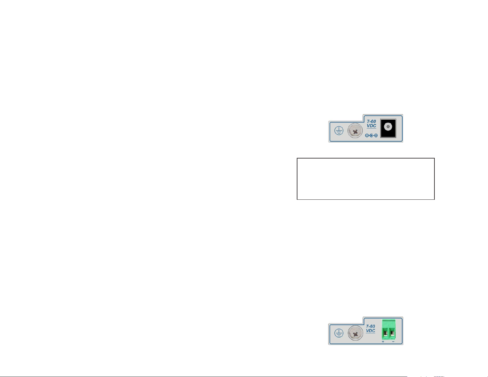
Route the power cord through the provided strain relief for additional support and
connect the barrel connector at the end of the wire on the AC/DC adapter to the barrel
connector on the module. Connect the AC/DC adapter to the AC outlet. Conrm
that the module has powered up properly by checking the Power LED located on
the front of the module.
AC Models Rear View: Barrel Connector for AC/DC Power Adapter
NEVER ATTEMPT TO OPEN THE CHASSIS OR
SERVICE THE POWER SUPPLY. OPENING THE
CHASSIS MAY CAUSE SERIOUS INJURYOR DEATH.
THERE ARE NO USER REPLACEABLE OR
SERVICEABLE PARTS IN THIS UNIT.
WARNING!!!
DC Power - Standalone
This module is intended for installation in restricted access areas. (“Les matériels
sont destinés à être installés dans des EMPLACEMENTS À ACCÈS RESTREINT”).
A restricted access area can be accessed only through the use of a special key, or
other means of security.
The over current protection for connection with centralized DC shall be provided in
the building installation, and shall be a UL listed circuit breaker rated 20 Amps, and
installed per the National Electrical Code, ANSI/NFPA-70.
Appropriate overloading protection should be provided on the DC power source
outlets utilized.
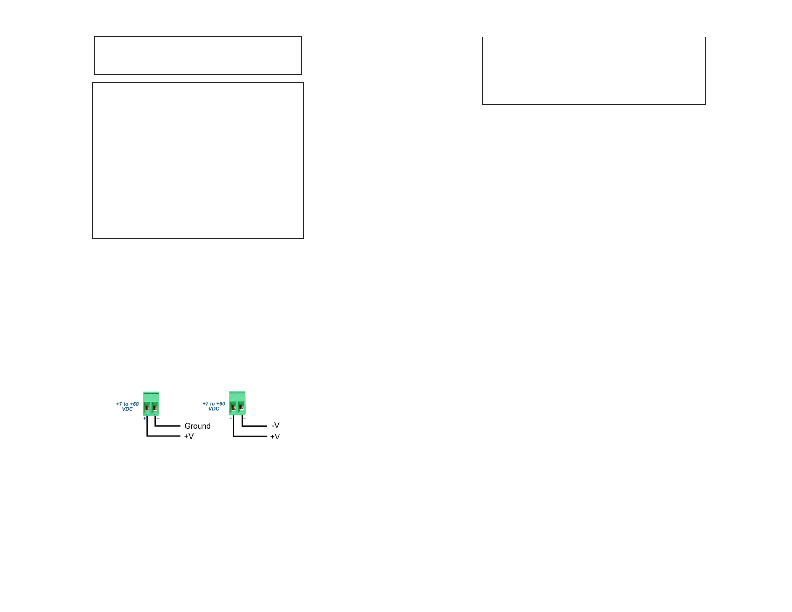
The standalone module requires +7 to +60VDC inclusive of tolerances (1.5A @
9VDC max rated power). See specication table for specic model requirements.
Appropriate overloading protection should be provided on the DC power source
outlets utilized.
DC Models Rear View: 2-Pin Terminal for DC Power
Page 8
Congure the DIP-switches on the remote module for “Self Diagnostic Circuit Test
for Remote Module” (DOWN, DOWN, UP, UP).
Congure the DIP-switches on the local modules for “Self Diagnostic Circuit Test
for Local Module” (UP, UP, UP, UP).
The local XG+ will initiate the circuit test (all DIP-switches to UP) by generating
and sending a test pattern out Port 1 to the remote XG+. Once the remote XG+
detects a good test pattern, the remote XG+ will generate and send a test pattern
back to the local XG+. No data is transmitted on Port 2 of either module when the
self diagnostic circuit test is enabled.
A successful test will produce a green blinking (5Hz) P1 LB LED on the local XG+
and a green blinking (1Hz) P1 LB LED on the remote XG+. If the local XG+ does
not receive a valid response, the P1 LB LED will be blinking amber (5Hz). When
the self diagnostic circuit test is initiated, the trafc received on Port 2 of both XG+
converters will be discarded.
If loopback has been initiated, self diagnostic circuit test DIP-switches will
be ignored. If self diagnostic circuit test has been initiated, loopback DIP-
switches will be ignored.
2) INSTALLING THE MODULE
Wall Mounting - Standalone Module
The wall mounting height of the module should be less than or equal to 2 meters
(6.6 feet) from the oor.
The standalone module is available with or without integrated mounting brackets.
When using the standalone module with integrated mounting brackets, use the four
mounting holes on the module to secure the module to the wall. The module can
accommodate #6 screws (not included).
Standalone modules without mounting brackets can use the optional mounting
bracket kit (2x 4381). Use the four mounting holes on the module to secure the
module to the wall. The module can accommodate #6 screws (not included).
Installation of the module should be such that the air ow in the front, back, side
and top vents of the switch are not compromised or restricted.
The accessory cables should have their own strain relief and do not pull down on
the module.
Rack Mounting - Standalone Module
The standalone modules with integrated mounting brackets or using the optional
mounting bracket kit can be rack mounted using the optional Rack Mount Shelf
(8260-0). Refer to the Rack Mount Shelf user manual (040-08260-001x) for the
proper installation guidelines.
Follow the same guidelines above when rack mounting the module.
Chassis Mounting - Plug-in Modules
Caution: Use proper ESD protection to reduce the risk of damage to your equipment.
Page 7

NEVER ATTEMPT TO OPEN THE CHASSIS OR
SERVICE THE POWER SUPPLY. OPENING THE
CHASSIS MAY CAUSE SERIOUS INJURYOR DEATH.
THERE ARE NO USER REPLACEABLE OR
SERVICEABLE PARTS IN THIS UNIT.
WARNING!!!
Make sure to disconnect the power and ground cables before removing the
equipment.
4) CONNECT CABLES
a. Insert the appropriate XFP or SFP+ transceivers into the corresponding port
receptacles on the XG+.
NOTE: The release latch of the transceiver must be in the closed position before
insertion.
b. Connect an appropriate multimode or single-mode ber cable to the ber
transceiver ports on the XG+. It is important to ensure that the transmit (Tx)
is attached to the receive side of the device at the other end and the receive
(Rx) is attached to the transmit side.
Both transceivers must be installed for the module to properly function. When
only one transceiver is installed, the transmitter of the installed transceiver
is disabled.
Page 10
WARNING: OnlyaDC power source that complies with
safety extra low voltage (SELV) requirements can be
connected to the DC-input power supply.
WARNING REGARDING EARTHING GROUND:
o
o
o
o
This equipment shall be connected to the DC supply
system earthing electrode conductor or to a bonding
jumper from an earthing terminal bar or bus to which the
DC supply system earthing electrode is connected.
This equipment shall be located in the same immediate
area (such as adjacent cabinets) as any other equipment
that has a connection between the earthed conductor of
the same DC supply circuit and the earthing conductor,
and also the point of earthing of the DC system. The DC
system shall not be earthed elsewhere.
The DC supply source is to be located within the same
premises as this equipment.
There shall be no switching or disconnecting devices in
the earthed circuit conductor between the DC source and
the earthing electrode conductor.
Locate the DC circuit breaker of the external power source, and switch the circuit
breaker to the OFF position.
Prepare a power cable using a three conductor insulated wire (not supplied) with
12AWG to 14AWG thickness. Cut the power cable to the length required.
Strip approximately 3/8 of an inch of insulation from the power cable wires.
Connect the ground wire to the grounding screws on the back of the module.
Connect the power cables to the module by fastening the stripped ends to the DC
power connector.
WARNING: The positive lead of the power source must be connected to the “+”
terminal on the module and the negative lead of the power source to the “-“ terminal
on the module as shown below.
Power Options
WARNING: Note the wire colors used in making the positive, negative and ground
connections. Use the same color assignment for the connection at the circuit breaker.
Connect the power wires to the circuit breaker and switch the circuit breaker ON.
If any module are installed, the Power LED will indicate the presence of power.
During the installation, ensure that the ground potentials are maintained throughout
the system connections. This includes but not limited to the power source ground
and any shielded cabling grounds.
Page 9

5) VERIFY OPERATION
Once the module has been installed and congured per steps 1 and 2, verify the
module is operational by viewing the LED indicators.
The XG+ does not generate data, it only passes the data it receives from the
connected equipment. Both transceivers must be installed and connected in
order for the module to pass data trafc. P1/P2 Lk LED indicates an optical
connection has been established. It does not indicate the presence of data
trafc. Check the attached equipment for conrmation of data trafc.
Legend OFF State Color ON/Blinking State
Pwr Off – No power Green Green – Power On
P1/P2
Lk
Off – No Transceiver
detected or no ber link Green
Green Solid – Fiber link
Green Blinking (1/2Hz) – When SFD is enabled,
receiving remote ber fault signal from link partner
P1/P2
Stat
Off – Transceiver does not
support digital diagnostic
or no transceiver installed
Green Green Solid – Transceiver supports digital
diagnostic and no DDMI Alarm Detected
Amber Amber Solid – Transceiver supports digital
diagnostic and DDMI alarm detected
P1 LB Off – Port loopback mode
not enabled or congured
Green
Green Solid – Port set to Loopback mode and port
in loopback
Green Blinking (1 Hz) - Port responding to Circuit
Test activation with valid Circuit Test response
Green Blinking (5 Hz) - Port initiating Circuit Test
and receiving valid Circuit Test response
Amber
Amber Solid – Port set to loopback mode, but XFP
does not support loopback
Amber Blinking (5 Hz) - Port initiating Circuit Test
and not receiving valid Circuit Test response
P2 LB Off – Port loopback mode
not enabled or congured
Green Green Solid – Port set to Loopback mode and port
in loopback
Amber Amber Solid – Port set to loopback mode, but XFP
does not support loopback
P1 Lk,
P1 Stat,
P2 Lk,
P2 Stat
- Amber
Simultaneous Amber Blinking (1Hz) – Ports disabled
due to unsupported power level of the installed
XFP transceiver. Module drawing more current than
allowed
LED Indicators
Page 11
SPECIFICATIONS
Description iConverter XG+
Protocol-Transparent Media Converter/Transponder
Standard
Compliances
IEEE 802.3ae (10G Ethernet),
SONET OC-192, SDH STM-64,
INCITS T11.2 (10G Fibre Channel),
ITU-T G.709 OTN,
CPRI option 6, 7, 7A and 8
Regulatory
Compliances
UL, CE, FCC Class A, NEBS 3 Compliant,
RoHS, WEEE, REACH, SFF-8077, SFF-8477
Frame Size Unlimited
Port Types Fiber: Power Level 1 and 2 SFP+ transceivers
Power Level 1,2, 3 and 4 XFP transceivers
Cable Types Fiber: Multimode: 50/125µm, 62.5/125µm
Single-mode: 9/125µm
AC Power
Requirements
AC Adapter: 100 - 240VAC/50 - 60Hz
0.20A @ 120VAC (max)
DC Power
Requirements
DC Input: 3.3VDC, 3.75A @ 3.3VDC (Max)
(Backplane)
DC Input: 7 - 60VDC
(Terminal Block) 1.5A @ 9VDC, 1.1A @ 12VDC
2-Pin Terminal (non-isolated)
DC Input: 7 - 60VDC
(AC Adapter) 1.5A @ 9VDC, 1.1A @ 12VDC
2-Pin Terminal (non-isolated)
Dimensions
W x D X H
Plug-in: 0.85” x 4.5” x 2.8” (21.6 mm x 114.3 mm x 71.1 mm)
Standalone: 3.1” x 4.8” x 1.0” (78.7 mm x 121.9 mm x 25.4 mm)
Standalone: 3.8” x 4.8” x 1.0” (96.5 mm x 121.9 mm x 25.4 mm)
(Wall-mount)
Weight
Plug-in: 8 oz.; 226.8 grams
Standalone: 1.0 lb.; 453.6 grams
Standalone: 1.5 lbs.; 680.4 grams
(w/Adapter)
Temperature
Commercial: 0 to 50°C
Wide: -40 to 60°C
Extended: -40 to 75°C
Storage: -40 to 80°C
Humidity 5 to 95% (non-condensing)
Altitude -100m to 4,000m
MTBF (hrs)
Plug-in: 770,000
Standalone: 106,000
AC/DC Adapter: 96,000
Warranty Lifetime warranty with registration and 24/7/365 free Technical Support
Page 12
040-8599R-001D 02/21
Table of contents
Other OST Media Converter manuals

OST
OST OmniConverter GHPoE/S User manual

OST
OST iConverter 2GXT User manual

OST
OST iConverter T3 User manual

OST
OST iConverter GX/TM2 User manual

OST
OST iConverter User manual

OST
OST iConverter XG Supplement

OST
OST iConverter 10/100M User manual

OST
OST OmniConverter GPoE/S User manual

OST
OST iConverter 10GXT User manual

OST
OST iConverter CWDM/X User manual