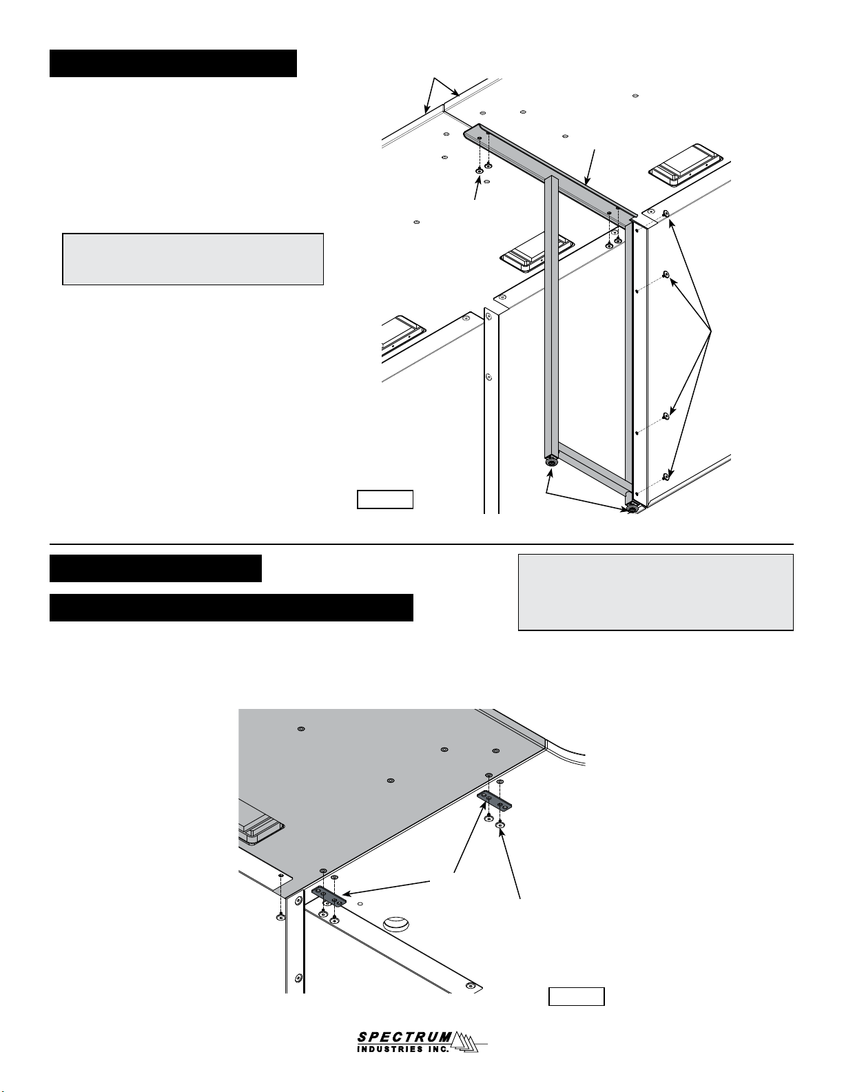
Worksurface-to-top of Equipment Rack:
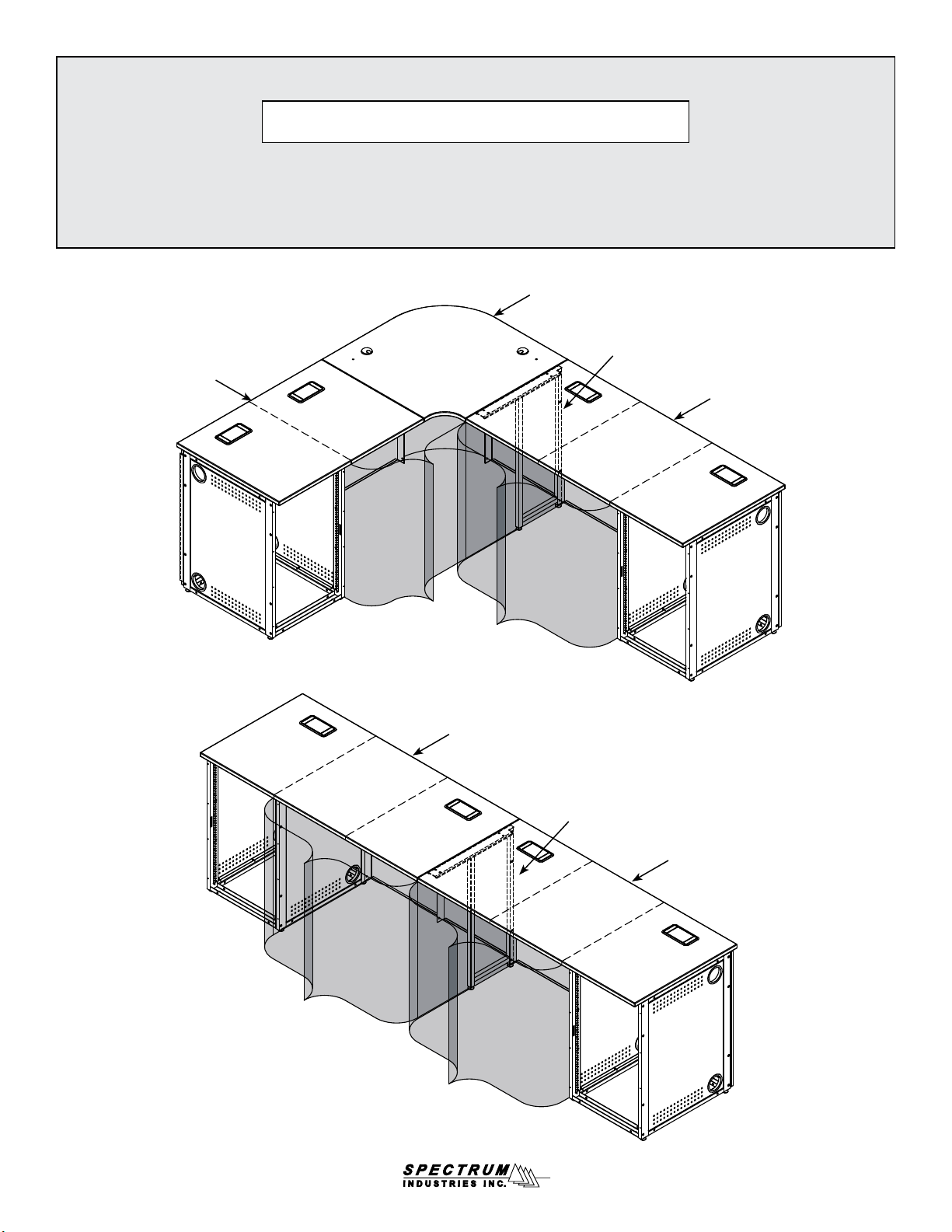
1. Set the worksurface onto the equipment rack and any adjacent
assembled wall ller panels (if applicable). Figure 7B.
2. Align the worksurface and equipment rack mounting holes.
3. Attach worksurface with (4) 1/4-20 x 15mm JC bolts.
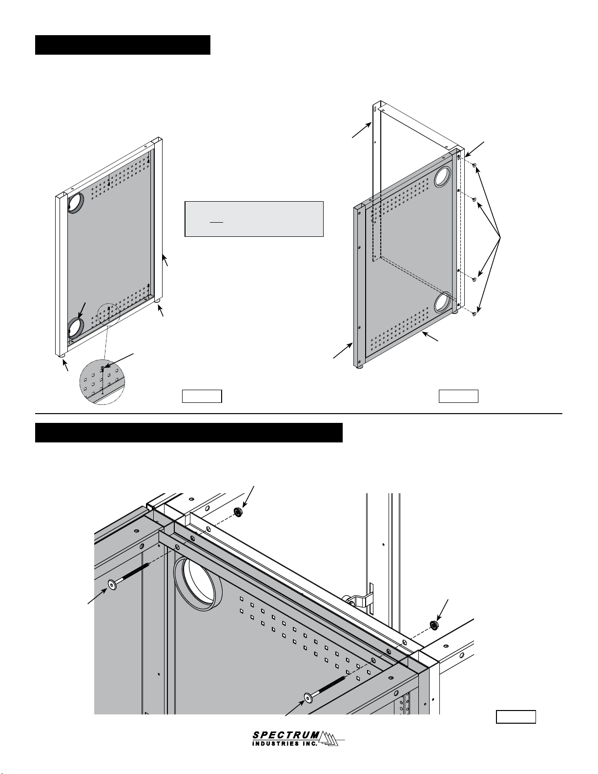
1. Attach each worksurface bracket to the equipment rack with (1)
1/4-20 x 50mm JC bolt and (1) 1/4-20 serrated anged locknut
(attached from inside eq rack). (The slotted side of the bracket will
attach to the worksurface.) Do not tighten completely. Figure 7C.
2. Set the worksurface onto the assembled wall ller panel(s) and
worksurface brackets and align the mounting holes.
3. Attach worksurface with 1/4-20 x 15mm JC bolts.
4. Align the tops of the worksurfaces and tighten all screws securely.
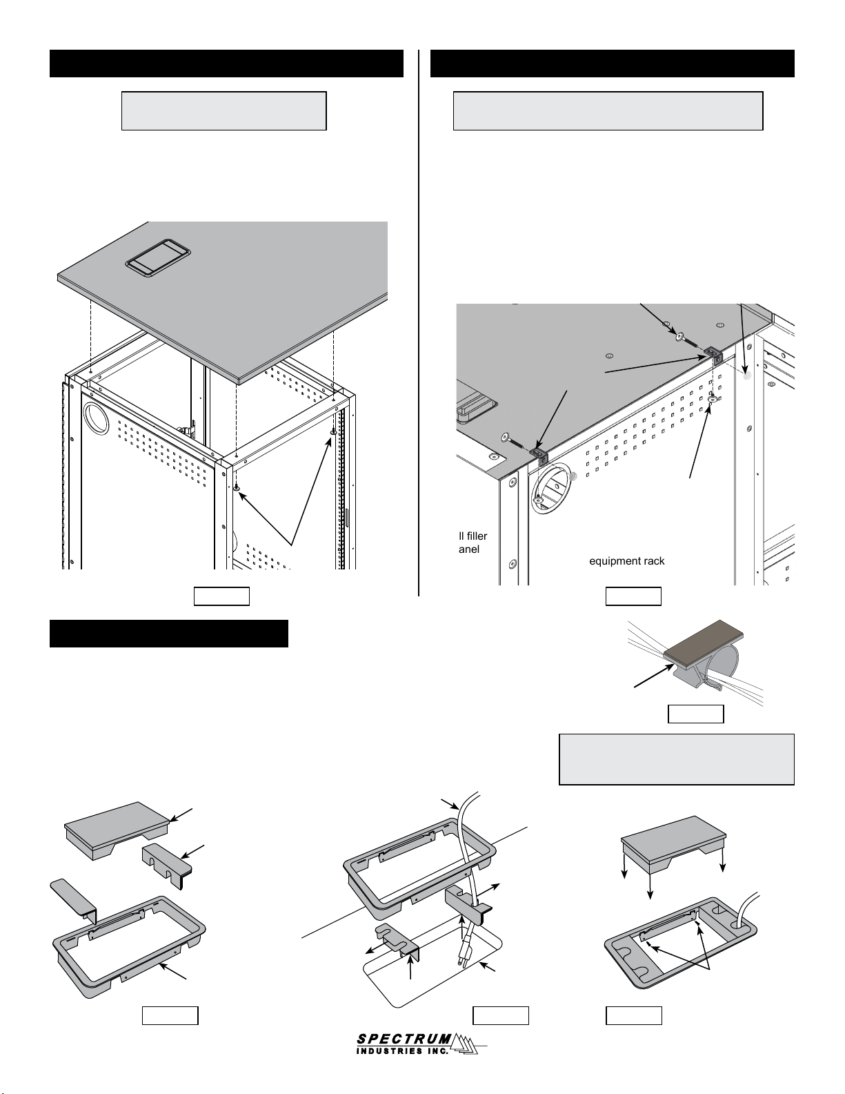
Grommets and Cord Clips
1. Remove the entire grommet assembly from the worksurface.
2. Remove the center cover and slide out the cord receptacles. Figure 8A.
3. Turn the receptacles around to access the cord pass-through holes and slide back into
the grommet frame around the cord(s). Figure 8B.
4. Re-install the grommet assembly into the worksurface cutout and replace the center
cover. Figure 8C. Optional: Install (2) #6 x 5/8” PHSM screws through the side of the
grommet frame to secure grommet to the worksurface.
5. Apply cord clips to underside of worksurface where needed to route cords. Figure 8D.
(Clips only included with radius corner and wall ller panels.)
Worksurface-to-Worksurface with Equipment Rack:
Figure 7C
Note: This is the connection between a worksurface of equal
height to another worksurface above an equipment rack.
Note: This is the attachment of a work-
surface to the top of an equipment rack.
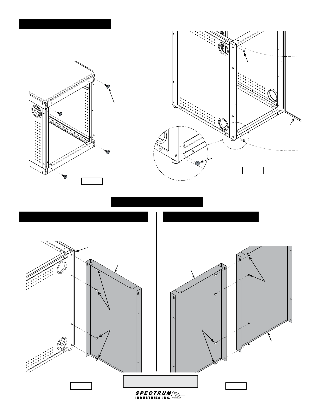
wall ller
panel
equipment rack
Note: The grommets and cord clips provide cord
management when cords and wires are to be
routed to the worksurface from under the console.
Figure 8D
cord clip
0108630R7 Page 8 of 11
underside of
worksurface
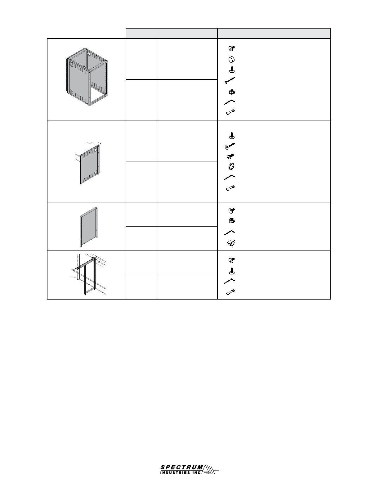
1/4-20 x 15mm
JC bolt
(1 per bracket)
worksurface
brackets
1/4-20 x 50mm JC bolt
(1 per bracket)
1/4-20 anged locknut
(1 per bracket-attach
from inside eq rack)
Figure 7B
worksurface
1/4-20 x 15mm
JC bolt
(4 required)
equipment rack
center cover
cord receptacle
grommet frame
Figure 8A Figure 8B Figure 8C
cord
worksurface
cutout (2) #6 x 5/8” PHSM
screws (secure to
worksurface-optional)