SpeedEPart Agri-Fab 45-0356 User manual

PRINTED IN USA FORM NO. 48974 (REV. 1/04)
OWNER'S
MANUAL
Model No.
45-0356
3-POINT HITCH
DISC CULTIVATOR
• Safety
• A embly
• Operation
• Maintenance
• Part
CAUTION:
Read Rule for
Safe Operation
and In truction
Carefully
the fastest way to purchase part
www.speedepart.com
Agri-Fab¨
Digitally signed by WMV-Dresden
DN: cn=WMV-Dresden, c=DE,
o=WMV-Dresden,
Date: 2017.01.26 13:00:41 +01'00'
WMV-
Dresden
2
SAFETY RULES
Remember, any power equipment can cau e injury if operated improperly or if the u er doe not under tand how to
operate the equipment. Exerci e caution at all time when u ing power equipment.
1. Read thi owner' manual before u ing thi equip-
ment.
2. Do not allow children to operate the tow vehicle or
the di c cultivator.
3. Do not allow adult to operate the tow vehicle or the
di c cultivator without proper in truction.
4. Do not allow anyone to ride on the tow vehicle or the
di c cultivator.
5. Before lowering the di c cultivator, make ure no
one i near the area of operation.
6. Lower the di c cultivator when leaving the tow
vehicle unattended.
7. Wear appropriate footwear when u ing the di c
cultivator. The di c edge are harp!
8. Tow vehicle braking and tability may be affected
by the di c cultivator. Drive lowly with the di c
cultivator in the tran port po ition. Stay off steep
slopes.
9. Stop and in pect the equipment for damage after
triking an object. Repair any damage before con-
tinuing operation.
10. Keep all nut and bolt tight and be ure that the
equipment i in afe operating condition.
11. Before attaching or removing the di c cultivator,
park and lock the tow vehicle in a afe condition.
LOOK FOR THIS SYMBOL TO POINT OUT
IMPORTANT SAFETY PRECAUTIONS. IT
MEANS – ATTENTION! BECOME ALERT!
YOUR SAFETY IS INVOLVED.
CAUTION: VEHICLE BRAKING AND
STABILITY MAY BE AFFECTED BY THE
ADDITION OF AN ACCESSORY OR AN
ATTACHMENT. BE AWARE OF CHANG-
ING CONDITIONS ON SLOPES.
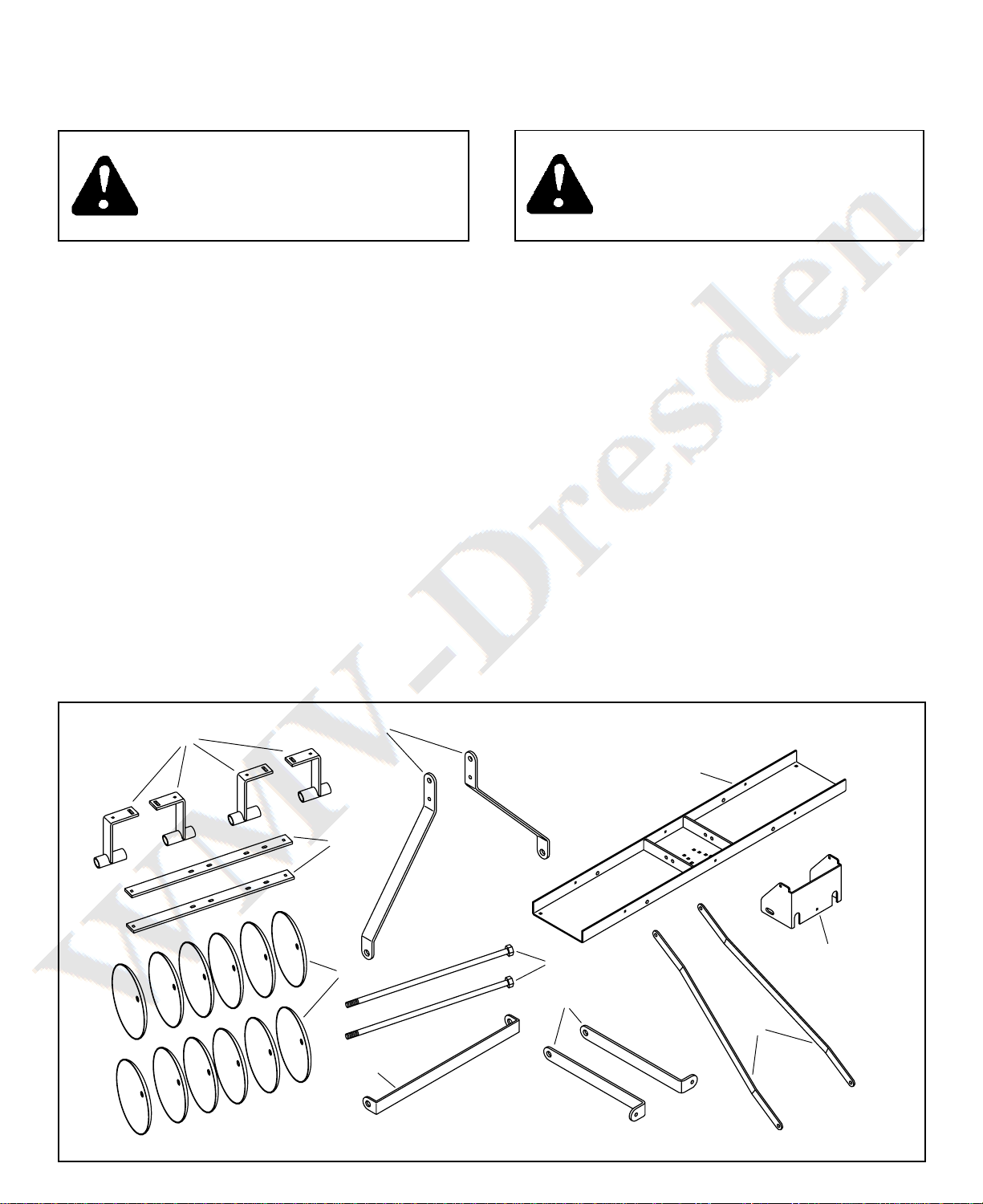
CARTON CONTENTS
1. Bearing Hanger Bracket (4)
2. Di c Anchor Strap (2)
3. Ma t Side (2)
4. Tray Frame
5. Di c Blade (12)
6. Cro Brace
7. Hex Bolt, 3/4" x 25" Lg. (2)
8. Ma t Exten ion Strap (2)
9. Ma t Lift Strap (2)
10.Weight Rack
11.Part Package ( ee page 3)
3
2
7
5
4
8
9
6
10
1

3
PARTS PACKAGE CONTENTS – PARTS SHOWN ACTUAL SIZE
S
KEY QTY. DESCRIPTION
A 1 Hex Bolt, 1/2" x 3-1/2"
B 2 Hex Bolt, 1/2" x 2-1/4"
C 4 Hex Bolt, 3/8" x 1-1/2"
D 8 Carriage Bolt, 3/8" x 1-1/4"
E 1 Hex Bolt, 3/8" x 1"
F 2 Hex Nut, 7/8"
G 1 Haircotter Pin
H 2 Hex Bolt, 1/2" x 1-1/4"
I 6 Spacer, 4.25" Lg.
J 4 Spacer, 4.50" Lg.
KEY QTY. DESCRIPTION
K 24 Flat Wa her, 2"
L 2 Lock Wa her, 7/8"
M 4 Flat Wa her, 1.25"
N 1 Spacer, 1.5" Lg.
O 2 Spacer, .75” Lg.
P 2 Hex Nut, Nylock, 3/4"
Q 13 Hex Nut, Nylock, 3/8"
R 5 Hex Nut, Nylock, 1/2"
S 2 Category 1 Pin
T 1 Pivot Pin
T
P
R
M
Q
L
K
G
F
J
I
E
D
H
C
B
A
N
O
Not to Size
4
ASSEMBLY
TOOLS REQUIRED FOR ASSEMBLY
(2) 9/16" Wrenche
(2) 3/4" Wrenche
(2) 1-1/8" Wrenche
(2) 1-5/16" Wrenche or 12" Adju table Wrenche
(1) Grea e Gun
Remove all loo e part and the hardware package from
the hipping carton. Then lay out and identify each part
and the common hardware a hown on page 2 and 3.
Be ure the carton i empty before it i di carded.
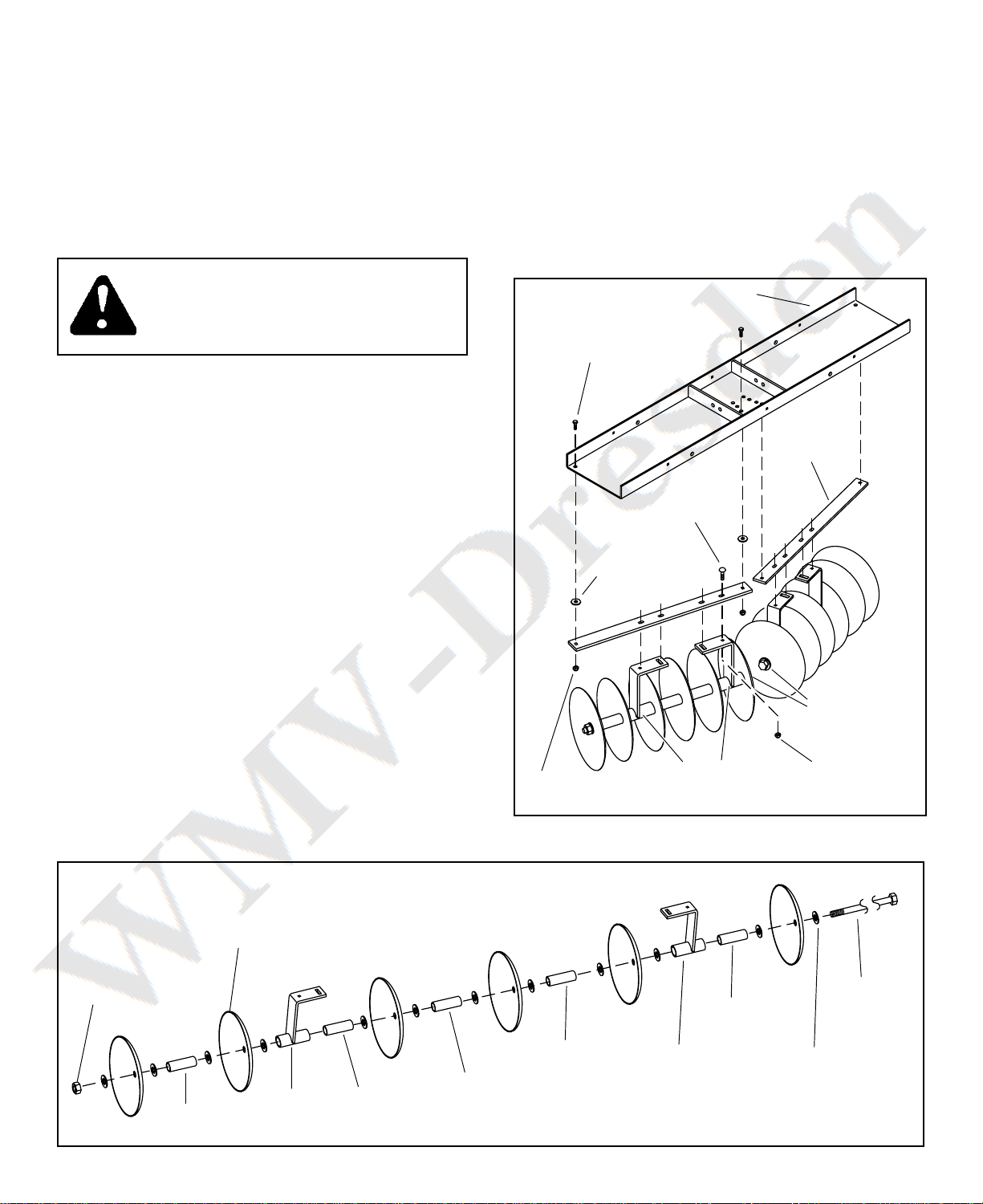
1. Refer to figure 1. A emble the following onto
each 3/4" x 25" hex bolt: ix di c blade , two
bearing hanger bracket , twelve 2" flat wa her ,
two 4.50" pacer , three 4.25" pacer and one
3/4" Nylock hex nut. The 4.50" pacer fit in ide
the bearing hanger bracket . Be ure all part are
a embled in the ame order a hown. Be ure
the bearing hanger bracket face toward each
other and that the di c blade all face the ame
direction. Tighten the Nylock hex nut.
IMPORTANT: U e only the 4.50" pacer (longe t)
in ide the bearing hanger bracket .
2. Add grea e to the bearing hanger bracket through
the grea e fitting until grea e i forced out the
end of the bracket .
CAUTION: DISC BLADES HAVE SHARP
EDGES. USE CARE IN HANDLING AND
ASSEMBLY. WEAR GLOVES FOR
EXTRA PROTECTION AGAINST CUTS.
3/8" NYLOCK
HEX NUT
3/8" NYLOCK
HEX NUT
BEARING
HANGER
BRACKET
DISC
ANCHOR
STRAP
3/8" x 1-1/2"
HEX BOLT
1.25" FLAT
WASHER
3/8" x 1-1/4"
CARRIAGE
BOLT
FACE HEAD
OF HEX BOLTS
TOWARD EACH
TRAY FRAME
FIGURE 2
3. A emble a di c anchor trap to a di c a embly
u ing four 3/8" x 1-1/4" carriage bolt and 3/8"
Nylock hex nut . Tighten. Repeat for other di c
a embly. See figure 2.
4. A emble the tray frame to the di c anchor trap
u ing four 3/8" x 1-1/2" hex bolt , four 1.25" flat
wa her , and four 3/8" Nylock hex nut . Fa ten to
the rear-mo t hole in the middle of the tray frame
for now. The di hed (concave) urface of the di c
blade hould face to the out ide with the head of
the 25" bolt on the in ide. Tighten. See figure 2.
FIGURE 1
3/4" x 25"
HEX BOLT
4.50"
SPACER
BEARING
HANGER
BRACKET
DISC
BLADE
4.50"
SPACER
4.25"
SPACER 2" FLAT
WASHER
3/4"
NYLOCK
HEX NUT
BEARING
HANGER
BRACKET
4.25"
SPACER
4.25"
SPACER

5
HAIRCOTTER PIN
MAST LIFT
STRAP
FIGURE 4
1-1/2 SPACER
1/2" NYLOCK
HEX NUT
PIVOT PIN
1/2" x 3-1/2"
HEX BOLT
MAST
SIDES
FIGURE 3
MAST EXTENSION
STRAP
CATEGORY
1 PIN
1/2" x 1-1/4"
HEX BOLT
1/2" NYLOCK
HEX NUT
MAST SIDE
7/8" HEX NUT
7/8" LOCK WASHER
TRAY FRAME
CROSS
BRACE
FIGURE 5
3/8" x 1"
HEX BOLT
WEIGHT RACK
3/8" NYLOCK
HEX NUT
1/2" x 2-1/4"
HEX BOLT
3/4" SPACER
1/2" NYLOCK
HEX NUT
END OF MAST
LIFT STRAP
TRAY
FRAME
7. In tall a pivot pin through the hole in the end of
the ma t ide and ecure the pin u ing the
haircotter pin. See figure 4.
8. Arrange the ma t lift trap a hown in figure 4.
A emble the trap and the 1-1/2" pacer be-
tween the ma t ide u ing a 1/2" x 3-1/2" hex bolt
and 1/2" Nylock hex nut. Do not tighten yet.
5. Attach two ma t exten ion trap to the front of
the frame tray o that the bent end of each trap
point outward. U e two 1/2" x 1-1/4" hex bolt
and two 1/2" Nylock hex nut . Do not tighten yet.
See figure 3.
6. At the other end of the ma t exten ion trap ,
attach the cro brace to the in ide and two ma t
ide to the out ide of the trap . U e the two
category 1 pin , two 7/8" lock wa her , and two
7/8" hex nut . Do not tighten yet. See figure 3.
9. Attach the weight rack to the back of the tray frame
u ing a 3/8" x 1" hex bolt and a 3/8" Nylock hex
nut. Do not tighten yet. See figure 5.
10. A emble the ma t lift trap on the out ide of the
frame tray brace u ing two 1/2" x 2-1/4" hex
bolt , 3/4" pacer and 1/2" nylock hex nut . Place
the pacer between the trap and the ide of the
weight rack. See figure 5. Refer al o to figure 6.
11. Tighten all loo e nut and bolt .
6
OPERATION
The di c cultivator i u ed to break up clod of dirt and
to uproot mall weed in plowed oil.
1. Before tarting, make ure the oil i dry enough by
queezing ome in your hand. If it form a ball that
doe n't crumble, the oil i too wet for di cing. Wet
oil will pack between the di c blade .
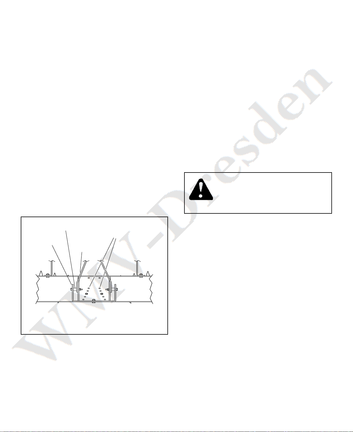
2. Adju t the di c to the de ired angle etting. The
di c cultivator ha five angle adju tment po ition .
The adju tment hole are located in the center of
the tray frame, in ide the weight rack. For more
aggre ive cultivating, move to the rear adju t-
ment po ition. For le aggre ive cultivating,
move to the front adju tment po ition.
To adju t the angle of a di c a embly, remove
the innermo t 3/8" x 1-1/2" hex bolt, 1.25" wa her,
and 3/8" Nylock hex nut that ecure the di c
anchor trap to the tray frame. Then move the di k
a embly o that the anchor trap i lined up with
the de ired adju tment hole. In tall the bolt and
wa her, then tighten the nut to lock in the etting.
Repeat thi procedure for the other di c a em-
bly. See figure 6.
CAUTION: DISC BLADES HAVE SHARP
EDGES. USE CARE WHEN WORKING
AROUND THE DISC CULTIVATOR. WEAR
GLOVES FOR EXTRA PROTECTION
AGAINST CUTS.
FIGURE 6
DISC ANGLE
ADJUSTMENT
HOLES
(TOP VIEW)
MAINTENANCE
1. Check for and tighten any loo e hardware before
each u e.
2. Clean the di c and lightly oil only bare metal after
each u e.
3. Lubricate all four bearing hanger bracket at grea e
fitting with grea e after each u e.
4. Remove all dirt and ru t. Touch up paint before
placing di c cultivator in torage.
5. Store di c cultivator in ide a dry area.
3. To break up dirt clod in plowed oil, tart di cing
lowly at fir t. A the clod are broken up, the
peed may be gradually increa ed. Di c the oil
u ing a cri cro pattern for be t re ult .
4. Up to 160 lb . of weight may be added to help
increa e penetration. 40 lb. uitca e weight can
be attached to the center weight rack, or concrete
block or other weight may be tied or trapped to
the cultivator tray. Before adding weight, the di c
cultivator hould be attached to the tow vehicle
with the cultivator lowered to the ground.
WEIGHT RACK
3/4" SPACER
MAST
LIFT
STRAP
7
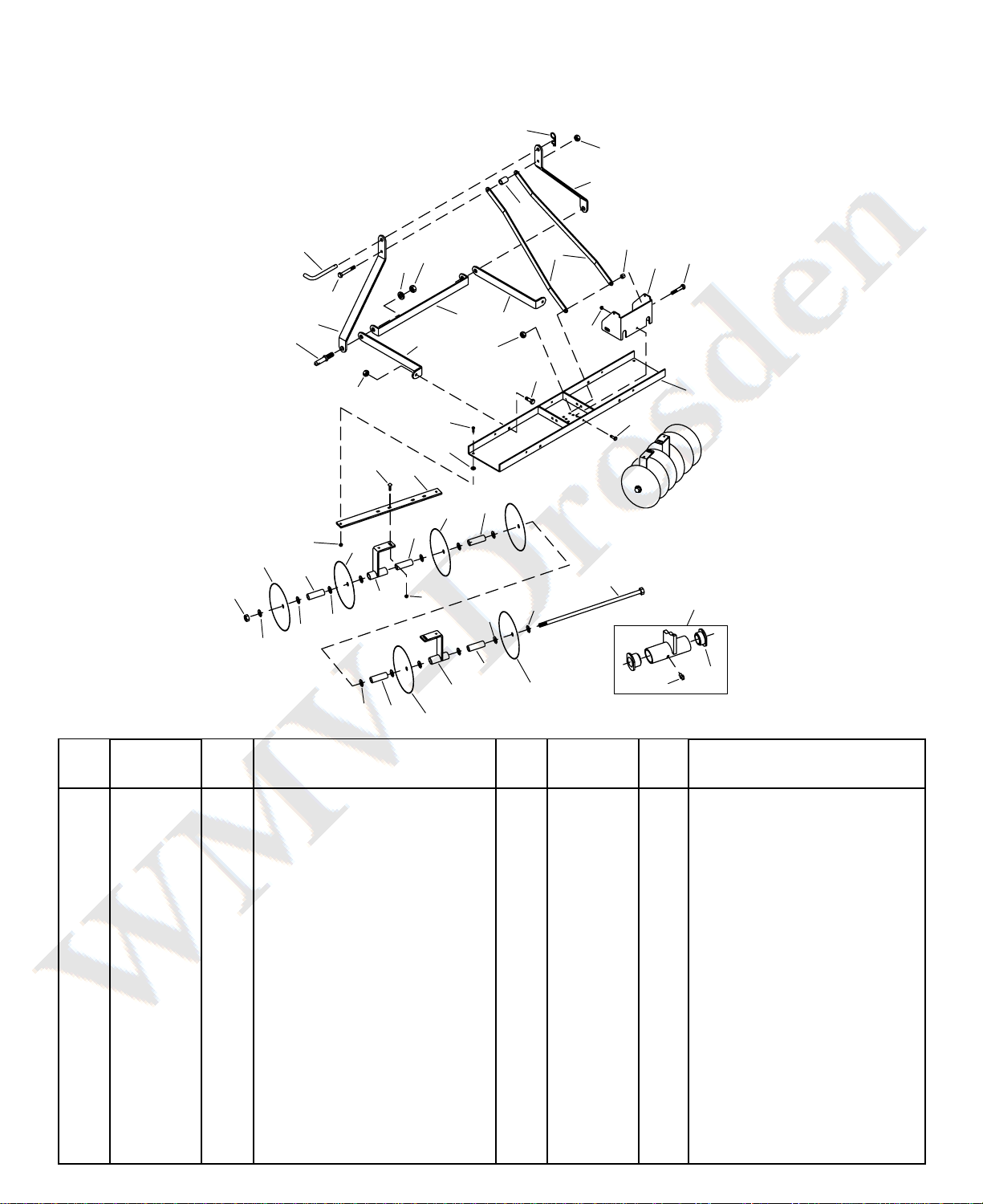
REPAIR PARTS FOR MODEL NO. 45-0356
3-POINT HITCH DISC CULTIVATOR
1 43343 1 Haircotter Pin, 1/8" x 2-3/8"
2 712-3083 5 Hex Nut, Nylock, 1/2"
3 25158 2 Ma t Side
4 25167 1 Spacer, .53" I.D. x .75" O.D.
x 1.5" Lg.
5 48978 1 Pivot Pin
6 48982 2 Lock Wa her, 7/8"
7 48970 2 Hex Nut, 7/8"
8 25180 2 Ma t Lift Strap
9 23368 2 Spacer, .76" I.D. x 1" O.D.
x .75" Lg.
10 25194 1 Weight Rack
11 HA180183 2 Hex Bolt, 1/2" x 2-1/4"
12 46526 1 Hex Bolt, 1/2" x 3-1/2"
13 48979 2 Category 1 Pin
14 25169 2 Ma t Exten ion Strap
15 25154 1 Cro Brace
16 43351 2 Hex Bolt, 1/2" x 1-1/4"
17 HA21362 13 Hex Nut, Nylock, 3/8"
REF. PART QTY. DESCRIPTION
NO. NO. REF. PART QTY. DESCRIPTION
NO. NO.
18 64781 1 Tray Frame
19 43001 1 Hex Bolt, 3/8" x 1"
20 710-0305 8 Carriage Bolt, 3/8" x 1-1/4"
21 25168 2 Di c Anchor Strap
22 736-0247 4 Wa her, .41" x 1.25" x .156"
23 43062 4 Hex Bolt, 3/8" x 1-1/2"
24 48911 2 Hex Nut, Nylock, 3/4"
25 46856 12 Di c Blade
26 46859 6 Spacer, .80" I.D. x 1" O.D.
x 4.25” Lg.
27 1540-162 24 Wa her, .77" x 2" x .1345"
28 63510 4 Bearing Hanger Bracket
29 24240 4 Spacer, .80" I.D. x 1" O.D.
x 4.50” Lg.
30 48966 2 Hex Bolt, 3/4" x 25" Lg.
31 44488 8 Bearing (included in 63510)
32 46858 4 Grea e Fitting (included in
63510)
48974 1 Owner Manual (not hown)
5
3
12
13
67
2
14
14
15
8
4
3
1
2
9
10
17
11
18
2
19
16
27
29
28
23
22
20 21
17
30
25
26
29
26
26
17
25
27
24 28
27 27
31
32
27
27
25 25
25
28

REPAIR PARTS
Agri-Fab, Inc.
303 We t Raymond
Sullivan, IL 61951
217-728-8388
www.agri-fab.com
the fastest way to purchase part
www.speedepart.com
© 2004 Agri-Fab, Inc.
Table of contents
Other SpeedEPart Tiller manuals


