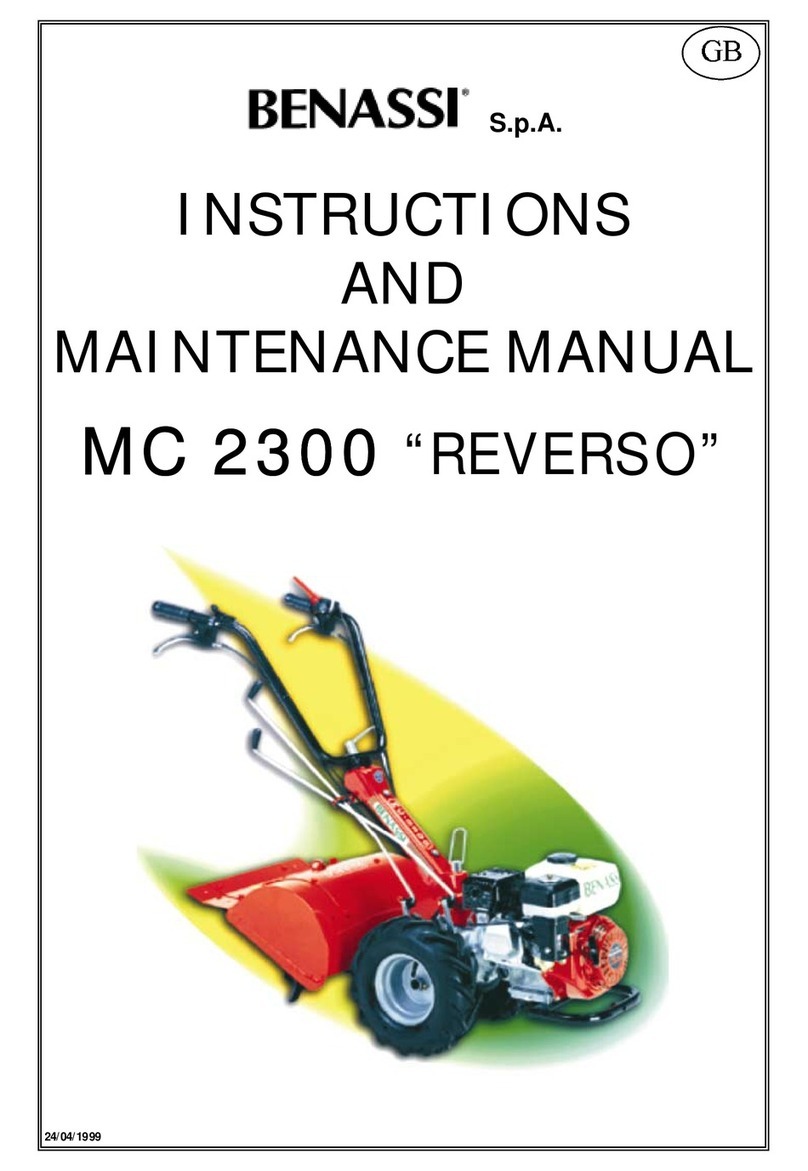
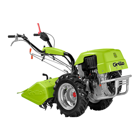
Benassi BL 10 Series Manual

S.p.A.
SERIES
BL 10
14/07/2008

SpA
BL 10
2
INTRODUCTION
KEY TO MACHINE PARTS
IDENTIFICATION AND TECHNICAL SPECIFICATIONS
PACKING AND TRANSPORT
SAFETY REGULATIONS
HOW TO START AND STOP
USE AND ADJUSTMENTS
MAINTENANCE
GUARANTEE
CERTIFICATION
Many thanks for choosing our product and welcome to our group of clients.
We are confident you will like our machine for its performance and ease of use.
Our longstanding experience in the sector, use of high quality materials, careful machining, all ensure a perfectly efficient
machine which, if used correctly and maintained as recommended, will offer you many years of use.
This handbook will provide you with all necessary information on use of the machine, its construction, its operating
characteristics, and on the applications, in addition to facilitating maintenance.
Please pay special attention to the regulations in this handbook preceded by this symbol:
ATTENTION
This symbol means that failing to observe these regulations could lead to personal injuries.
1. Accelerator - motor stop
2. Cutter movement engage/
disengage lever
3. Fuel tap
4. Fuel filler plug
5. Motor starter
6. Transport wheel
7. Cutters
8. Handle locking knob
9. Spur
10. Wheel adjusting knop
11. Primer
Overall dimensions (in mm)

SpA
BL 10
3
For the engine features see the engine instruction booklet delivered with the machine.
•All engines installed on this motorised hoe have a starting system with self-winding cord, as well as exhaust pipe protection.
•Engines installed on the BL 10 are lubricated with SAE 30 oil. Quantity of oil in engine: 0.6 lt.
•The transmission unit is lubricated with AGIP SPGRMU00 oil - quantity 11 hg.
GENERAL SPECIFICATIONS OF THE MOTORISED HOE:
1. Vee-belt and worm screw transmission; one forward gear.
2. Forward engage/disengage lever fitted on handle.
3. Engine stop device fitted on handle.
4. Handle can be dismantled to facilitate transport.
5. Height adjustable spur.
6. Standard supply cutter of 40 cm;
7. Front transfer wheel
To identify the machine (serial number, engine, weight, and power), read the data-plate located as shown in the photo. See Ref.
“A” of Fig. N°3.
oWIDTH: 80 cm
oDEPTH: 40 cm
oHEIGHT: 70cm
•Remove the motorised hoe from its packing.
•Install the handlebar as shown in picture 4, fitting it at the desired height as it is
adjustable in different positions, then secure it with the knob Ref. “A” (Fig. N°4).
•Adjust the coupling and disengagement lever of the tiller (Ref.”A”, Fig. N°5) by
setting the adjuster of the cable (Ref.”B” and “C”, Fig. N°5) so that if the lever is
lifted up the engines is in the most advanced position compared to the handlebar,
whereas when the lever (Ref. “A”, Fig. N°5) is down the engine is in the position closer to the handlebar.
•
It is important that the lever is adjusted in way that it doesn’t strain immediately but only next to the stop, that is to say when
is it next to the handgrip (see Fig.6).

SpA
BL 10
4
SECURITY RULES
•Carefully read the use and maintenance handbook supplied with the machine.
•Children under 16 years of age must not use the machine.
•The use is responsible for any damage because the machine responds to his/her commands.
•Any person who does not know the machine and has never used it, must read the use and maintenance handbook before
using the machine.
•If you are transporting the machine, empty petrol from the tank.
•If you put the machine out of service, make sure it cannot restart.
•Never work barefoot or wearing sandals. Prepare for work by wearing resistant shoes and long trousers. Before beginning
to work, inspect the work area, taking care to remove stones, sticks, metal wires and any other foreign body.
•Before starting the engine, the user must have a free working range of 5 metres.
•Dry off any petrol leaks.
•Always fill the tank while the engine is stopped. Filling up with and/or transfer of fuel must always be performed outdoors,
well away from fires or heat sources. Do not smoke during this operation.
•Before beginning to use the motorised hoe, learn to switch the engine off quickly, get to know the controls and learn how to
use the machine correctly.
•Do not use the engine in places where exhaust gases containing carbon monoxide can accumulate.
•Never use the motorised hoe if incomplete, or without its protective device. Never do any hoeing with the protective hood
OFF the machine.
•Do not fit, detach or clean the cutter or any tools while the engine is running.
•Attention! Do not work on gradients in excess of 50%.
We do not accept any responsibility whatever for any accidents caused by not observing these regulations.
TRANSPORT
•The machine is equipped with a small front wheel for the transport (see picture 5, D)
•The machine can be moved easily by lifting the handlebar (keeping the fuel cap closed for the Honda version).
•To transport the machine on a car it is possible to reduce the dimensions by simply removing the handlebar
(Picture 5, E), the spur (Picture1, 9) and the small wheel (Picture 1, 6) by unscrewing the knob (Picture 1, 10).
!
Whenever you are about to start the engine, always run the following checks very carefully:
•Is there fuel in the tank? Add fuel if necessary (see Fig. N°1)
•Check engine oil level: IMPORTANT: THERE IS NO OIL IN NEW MACHINES DELIVERED FROM THE FACTORY. In this
case, fill with oil up to the level of the oil plug stick.
•PLEASE CONSULT THE ITEM “FIRST START-UP” IN THE ENGINE USE AND INSTRUCTIONS HANDBOOK.
•Always start in the open air.

SpA
BL 10
5
STARTING STAGES
1. The fuel tap must be open Ref. 3” Fig N°1.
2. Position the accelerator lever in “START” position (see Fig. N°9 Ref, A).
3. Make sure that the transmission engagement lever is lifted up, see Fig. N°11 Ref A.
4. Grip the starter handle with one hand, Fig. N°11, pull gently until you feel resistance and then pull hard. When the motor has
started running, do not let go of the cord suddenly, but accompany it until fully rewound.
5. In all BL10 models, when the engine has been started, allow the accelerator lever to return to mid-stroke (see Fig. N°9).
Allow the engine to warm up properly before starting work.
6. To move the motorised hoe forward, grip the handles firmly and lower the lever Fig. N°6; in this way, transmission is
automatically engaged.
7. To stop the engine, move the accelerator handle to “Stop” position (see Fig. N°9) and, close the fuel tap. DO NOT tie the
transmission engagement lever to the handlebar knob while using the motorised hoe.
Pict. n. 8 Pict. n. 9
"
•The tiller is equipped with a small front transfer wheel that can be removed or rotated upwards, as shown in picture 7,,
during the hoeing work by operating on the adjusting knob (Ref.”10”, Fig.1).
•To move the motorised hoe forwards, use the transmission engage-disengage lever Fig. N°10.
•Always do this while the engine is idling, and, in any event, press the engaging lever slowly and then increase revs with the
accelerator lever.
•
The tiller is 40 cm wide and it has got 4 blades: 2 blades on each side.
•
The cutting part of the tiller must face the front of the machine.
•
The spur is secured by a through-pin (see Fig. N°12, Ref.”A”) and its height can be adjusted in 3 different positions
according to the hole selected for securing - the hole is on the spur.
#
Pict. n°11

SpA
BL 10
6
•To change engine oil, consult the supplied engine handbook. This also applies to the other maintenance jobs (spark plugs,
air filter, adjustments).
•Some of the transmission parts are oil-bath lubricated. The transmission unit does not required topping up, and the initial
quantity of oil ensures many hours (200) of use or 2 years use.
•When changing transmission oil, empty oil by first unscrewing the lower cover (see Fig. N°13), and the 4 screws Ref. “A”.
Pour in 1 hg of the recommended type of oil. Re-screw with the supplied wrench and screwdriver. Carry out this operation
every 200 hours (or after the first year for the first time and then every two years).
•The tension of the transmission belt can be adjusted by means of the regulators on the transmission cable (see Ref.”A” –
Fig.N°11 and 14).
•Periodically oil joints and control wires. Periodically clean the air filter cartridge. Do this more frequently, if working on dusty
soils.
•If the belt breaks or is excessively worn, call at your area dealer to replace the belt with one of the same type.
•Periodically check (at least once per season) tightness of nuts and bolts, especially those of the cutter.
•Always use gloves when working on the cutter.
•As concerns any mechanical jobs, especially during the guarantee period, we recommend you to contact the specialised
workshops of our concessionaires.
Pict. n°13

SpA
BL 10
7
The machine and accessories are guaranteed for 2 years: electrical or rubber parts are excluded. The manufacturer shall
replace free of charge any parts recognised as faulty: however, labour and transport shall always be charged to the client.
Guarantee requests should always be made through the manufacturer’s authorised resellers.
As concerns materials not produced by us, and, in particular, the engine, the rules specified by the relevant manufacturers
apply. Therefore, any requests for servicing work must be submitted to the respective specialised service centres in the different
areas.
For any problems and servicing requests, contact the reseller/dealer from whom you bought the machine.
Declaration CE in accordance with the Directives 98/37/CE
40017 San Matteo della Decima (BO) Italy Via Lampedusa 1 - Tel +39-051-820511
We hereby declare that the machine conforms with the essential requirements for health and safety in accordance with the
Directive 98/37/CE.
TYPE TILLER MODEL
For verification of the conformity with the afore-mentioned Directives reference has been made to following regulations: EN-
ISO12100-1, EN-ISO12100-2, EN 709 for tillers and cultivators and for the environmental acoustic emission.
CHAIRMAN OF THE BOARD
S. Matteo della Decima 23/07/2007
RESULT AND TESTS
TYPE TILLER MODEL
Acoustic pressure at the operator’s ear: LpA = from 76 dB (A) to 80 dB (A)
Testing conditions: 1,6 m height handle midpoint
Vibration at handles with weighting ISO.5349 value from 4,6 m/sec² to 10,06 m/sec²

SpA
BL 10
8
S.p.A.
VIA LAMPEDUSA 1
40010 S. MATTEO DELLA DECIMA (BO) - ITALY
! " # $ ! $ $ "
Web: www.benassi.eu e-mail: export@benassispa.it
Dealer’s Rubber Stamp
This manual suits for next models
2
Table of contents
Other Benassi Tiller manuals

Benassi
Benassi BL 6000 User manual
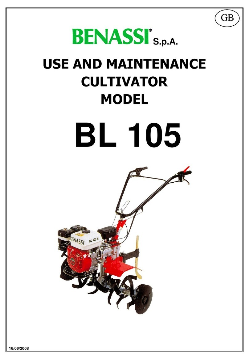
Benassi
Benassi BL 105 User guide
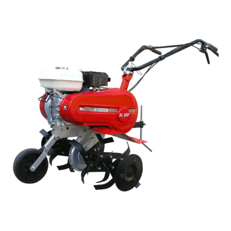
Benassi
Benassi BL 300 User guide
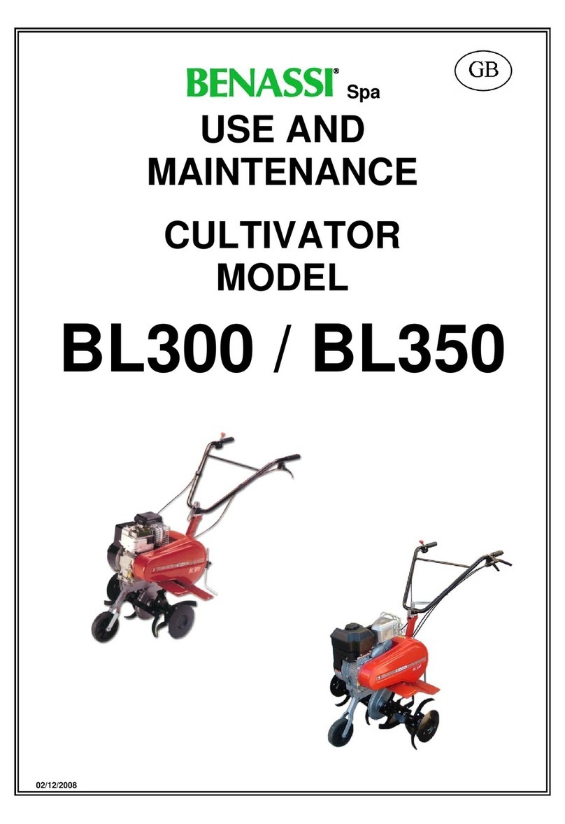
Benassi
Benassi BL 300 User guide
Benassi
Benassi BL304 Quick guide

Benassi
Benassi BL301H User manual
Benassi
Benassi BL 10 Manual

Benassi
Benassi BL 4000 User manual
Benassi
Benassi BL200 User manual
Benassi
Benassi BL30 User guide
Popular Tiller manuals by other brands
Vibrant Yard
Vibrant Yard Step ’N Tilt Lawn Aerator 3 Installation & owner's manual

Ikra
Ikra FEM 1500 operating instructions

MTD
MTD 214-100A Owner's operating service instruction manual
Wen
Wen TC1318 instruction manual

GreenWorks
GreenWorks 2800100 owner's manual

Husqvarna
Husqvarna crt51 instruction manual
