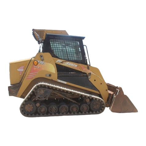
Sperry New Holland L-325 User manual

OPERATOR'S
MANUAL
SKID-STEER LOADER
L-325
42032514
~W
HOLL.AI\D
IReprinted I
Information should be free.
Please distribute this
document freely.

A
NOTE
TO
YOU, MR. OWNER:
This
manual
contains
information
concerning
the
operation,
maintenance
and
adjustment
of
your
Sperry
New
Holland
Loader.
It
should
be
carefully
read
before
attempting
to
operate
the
loader. You
wi
II
find
many
heIpfuI
pointers
which
will
assist
you
in
obtaining
the
superior
performance
for
which
it
was designed.
In
the design of your loader, emphasis has been placed on safety for operator protection.
However, careless and negligentoperation can still result
in
serious injuryto persons orproperty. Be
sure to read and follow all safety instructions in this manual.
Keep
this
manual available
for
ready reference.
Your
Sperry
New
Holland
dealer is interested in
your
obtaining
the
most
from
your
investment.
He
will
be
glad
to
answer
any
questions
that
you
may
have
about
your
loader.
When
major
service
is
required,
his
staff
of
trained
servicemen
is
ready
to
serve you.
When in need
of
parts, always
order
genuine
Sperry
New
Holland
service parts
from
your
Sperry
New
Holland
dealer. Be prepared
to
giveyourdealer
the
model
and serial
numberofyourengine
and
loader.
Locate
these
numbers
now
and
record
them
below.
Loader
Model
................................
.
Loader
Serial
Number
........................
.
Engine
Model
................................
.
Engine
Serial
Number
........................
.
ABOUT
IMPROVEMENTS
Sperry
New
Holland
is
continually
striving
to
improve
its
products.
We must,therefore, reserve
the
right
to
make
improvements
or
changes
when
it
becomes
practical
and
possible
to
do
so,
without
incurring
any
obligation
to
make
changes
or
additions
to
the
equipment
sold
previously.
A
ASERVICEMANUALAND/OR
PARTS
BOOK
IS
AVAILABLE
FROM
YOUR
SPERRY NEW
HOLLAND
DEALER
FOR A
NOMINAL
FEE.
CONTACT
YOUR
LOCAL
SPERRY
NEW
HOL-
LAND
DEALER
CONCERNING
PRICE
AND
AVAILABILITY
OF THESE
MANUALS.
CAUTION:
THIS
SYMBOL
IS
USED
THROUGHOUT
THIS
BOOK
WHENEVER
YOUR
OWN
PERSONAL SAFETY IS
INVOLVED.
TAKE
TIME
TO
BE
CAREFUL!
@ 1982 SPERRY
NEW
HOLLAND,
A
DIVISION
OF
SPERRY
CORPORATION,
NEW
HOLLAND,
PENNA. 17557

WARRANTY
SPERRY NEW HOLLAND SKID-STEER LOADERS
Sperry
New
Holland,
hereafter
called
the
Company,
warrants
to
each
purchaser
of a
new
Sperry
New
Holland
loader
from
an
authorized
Sperry
New
Holland
Dealer
that
the
loader
and
Sperry
New
Holland
attachments
are,
at
the
time
of delivery
to
such
purchaser,
free from defects
in
material
and
workmanship
and
that
the
loader
(except
tires,
tubes,
batteries,
and
equipment
not
bearing
the
name
of
Sperry
New
Holland)
will
be
warranted
for a
period
of
12
months
or
500
hours
of
operation,
whichever occurs first, if
used
and
serviced
in
accordance
with
the
recommendations
in
the
Operator's
Manual.
All tires, tubes, batteries,
and
equipment not bearing
the name of Sperry New Holland
are
warranted by the
selling dealer or themanufacturer thereof. Thisincludes
engines such as Deutz, Kohler,
and
Wisconsin
as
used
on
Sperry New Holland loaders.
This
warranty does not cover normal maintenance
and
service costs, charges for service calls andJ
or
transport-
ing equipment to location where repairs
are
accom-
plished; depreciation
or
damage caused
by
environment
(exposure
to
corrosiveorcontaminating materials), nor-
mal wear, or expendable components (such as filters
and
cutting edges).
No
warranty shall apply to damage resulting from ac-
cident, misapplication, abuse or failure to follow in-
structions for operation, maintenance
and
storage.
No
warranty whatsoever is made on
any
equipment or
part(s)
which have been rebuilt, modified, or altered
without the-consent or knowledge
of
the Company; or,
if
service, other
than
normal replacement.
of
senrice
items, is performed by someone
other
than
an
autho-
rized Sperry
New
Holland Dealer.
Except as set forth above, the Company shall have no
obligation or liability
of
any
kind on account of
any
of
its
equipment, and shall
not
be
liable for special
or
con-
sequential damages.
The
Company makes no other war-
ranty, express or implied, and specifically the Com-
pany
DISCLAIMS
ANY
IMPLIED
WARRANTY
OF
MERCHANTABILITY
OR
FITNESS.
TO THE OWNER
Leased or Rented Units
If
a
unit
is
leased
or
rented,
the
warranty
period
starts
on
the
date
the
unit
is first
leased
and/
or
rented
and
if
the
unit
is
sold
prior
to
the
expiration
of
the
warranty,
the
warranty
will
continue
in
effect for
the
re~
mainder
of
the
warranty
period.
About Improvements
Sperry
New
Holland
is
continually
striving
to
improve
its
products,
and
therefore
reserves
the
right
to
make
improvements
or
changes
when
it
becomes
practical
and
possible
to
do so,
without
incurring
any
obligations
to
make
changes
or
additions
to
the
equipment
sold previously.

OWNER ASSISTANCE
We at
Sperry
New
Holland
and
your
Sperry
New
Holland
dealer
want
you
to
be
completely
satisfied
with
your
investment.
Normally
any
problems
with
your
equipment
will
be handled by
your
dealer's Service Department. Sometimes, however,
misunderstanding
can occur. If
your
problem
has
not
been handled
to
your
satisfaction, we suggest
the
following:
1.
Contact
the
owner
or
General
Manager
of
the
dealership,
explain
the
problem, and request
assistance. When
additional
assistance is needed
your
dealer has
direct
access
to
our
branch
office.
2.
If
you
cannot
obtain
satisfaction
by
doing
this,
contact
the
Sperry
New
Holland
branch
office
in
your
area and
provide
them with:
•
Your
name, address and
telephone
number
•
Machine
Model and Serial
Number
• Dealership name and address
•
Machine
purchase date and
amount
of
use
• Nature
of
problem
Charlotte
PO
Box
33547
Charlotte,
NC
28233
(704) 392-8115
Columbus
PO
Box
28207
Lincoln
Village Br.
Columbus,
OH 43228
(614) 276-7161
Dallas
PO
Box
5488
Arlington,
TX 76011
(817) 649-1555
Denver
PO
Box
39124
Montbello
Station
Denver,
CO
80239
(303) 373-1010
Fresno
PO
Box
7796
Fresno,
CA
93727
(209) 291-6661
Joliet
PO
Box 2009
Joliet, IL 60434
(815) 725-7464
Kansas City
15300
W.
109th St.
Lenexa,
KS
66219
(913) 888-7000
Memphis
PO
Box 18519
Memphis,
TN
38118
(901) 362-1161
Minneapolis
PO
Box
1540
Twin
City
Airport,
MN 55111
(612) 454-6300
Syracuse
PO
Box
10
Liverpool, NY 13088
(315) 457-6551
3.
If
you
need
further
assistance contact:
Sperry
New
Holland
Consumer
Services
Department
Mail
Station 500
New Holland,
PA
17557
(717) 354-1545
Calgary
Box
1616, Main PO
Calgary,
AB
CANADA
T2P 2M7
(403) 273-6771
Toronto
PO
Box
7000
Brampton,
ON
CANADA
L6V 2M9
(416) 457-2720
Winnipeg
PO
Box
77
Winnipeg, MB
CANADA
R3C 2L4
(204) 474-2491
When
contacting
Sperry
New
Holland's
branch
office
or
Consumer
Services
Department
be aware
that
your
problem
will
likely
be resolved in
the
dealership,
using
the
dealer's facilities,
equipment
and personnel. So it
is
important
that
your
initial
contact
be
with
the
dealer.

CONTENTS
ABOUT
IMPROVEMENTS
.........................................................
2
A NOTE
TO
YOU, MR. OWNER
....................................................
2
SAFETY INFORMATION
...........................................................
4
SAFETY DECALS
..................................................................
6
OPERATION
.......................................................................
8
PRE-STARTING CHECK LIST
..................................................
13
NEW LOADER RUN-IN
.........................................................
13
STARTING THE LOADER
......................................................
13
STOPPING THE LOADER
......................................................
14
LOADER OPERATION
............................................................
15
FIELD OPERATION
...............................................................
18
SERVICE
AND
LUBRICATION CHARTS
.................................
21
and
22
PERIODIC SERVICE
..............................................................
23
MAINTENANCE
AND
ADJUSTMENTS
...........................................
30
STORING THE LOADER
.........................................................
38
SERVICE CHART
.................................................................
41
TROUBLESHOOTING
............................................................
42
TROUBLESHOOTING -
HYDRAULIC
SYSTEM
................................
42
OPTIONAL
EQUIPMENT
AND
REFERRAL
ATTACHMENTS
.....................
43
SPECIFICATIONS
................................................................
47
INDEX
............................................................................
49
DELIVERY REPORT
....................................................
after INDEX
h DANGER!
\
..
FASTEN SEAT BELT
'
~
' BEFORE STARTING ENGINE!
I THIS LOADER IS A VERY STABLE
UNIT
BUT
IT
CAN
BE UPSET IF THE OPERATOR
STOPS SUDDENLYWHEN BUCKETIS RAISED
AND LOADED.
THEREFORE,
DO
NOT
START ENGINE
BE-
FORE SECURELY
FASTENING
THE
SEAT
BELT.
3

SAFETY
INFORMATION
UNSAFE
OPERATING
PRACTICES
AND
IMPROPER USE OF THE LOADER
AND
ITS
ATTACHMENTS
ON THE PART OF THE OP-
ERATOR CAN RESULT IN INJURIES.
OB-
SERVE THE FOLLOWING SAFETY PRECAU-
TIONS
AT
ALL
TIMES:
1. GIVE COMPLETE
AND
UNDIVIDED
AT-
TENTION
TO
THE
JOB
AT
HAND
SO
COMPLETE
CONTROL
OF THE LOADER
IS
MAINTAINED
AT
ALL
TIMES.
2.
DRIVE SLOWLY OVER ROUGH
GROUND
AND
ON
SLOPES. KEEP
ALERT
FOR
HOLES, DITCHES
AND
OTHER IRREGU-
LARITIES
THAT
MAY CAUSE LOADER
TO
OVERTURN.
3.
AVOID
STEEP
HILLSIDE
OPERATION
WHICH
COULD
CAUSE
LOADER
TO
OVERTURN.
4.
REDUCE SPEED WHEN
TURNING
SO
THERE
IS
NO
DANGER
OF
LOADER
OVERTURNING.
5.
ALWAYS
LOOK
BEHIND YOU BEFORE
BACKING
UP.
6.
MAINTAIN
PROPER TRANSMISSION
OIL
LEVEL
TO
PREVENT LOSS OF BRAKING
CONTROL
7.
DO
NOT
ALLOW
CHILDREN
TO
OPER-
ATE THE LOADER.
8.
DO
NOT
ALLOW
ADULTS
TO
OPERATE
LOADER
WITHOUT
PROPER
INSTRUC-
TION.
OSHAREQUIRES
THAT
ALL
OPERATORS
BE INSTRUCTED
ON
THE PROPER OP-
ERATION OF THE
MACHINE
BEFORE
THEY OPERATE THE UNIT.
9.
DO
NOT
ALLOW
PASSENGERS
TO
RIDE
ON LOADER
AT
ANY TIME.
10. DO
NOT
OPERATE LOADER IN ANY PO-
SITION
OTHER
THAN
WHILE IN THE OP-
ERATOR'S SEAT WITH THE SEAT
BELT
SECURELY FASTENED.
11. BEFORE STARTING ENGINE, BE SURE
ALL
OPERATING
CONTROLS
ARE
IN
NEUTRAL.
12. NEVER OPERATE LOADER ENGINE IN A
CLOSED
BUILDING
WITHOUT
ADE-
QUATE VENTILATION.
13. REFUEL LOADER OUTDOORSWITH THE
ENGINE
SHUT
OFF. REPLACE FUEL CAP
SECURELY. USE AN APPROVED FUEL
CONTAINER.
DO
NOT
SMOKE WHEN
HANDLING
FUEL. AVOID SPILLING.
14. AFTER OPERATING THE ENGINE, NEV-
ER
TOUCH
MUFFLER, EXHAUST PIPE
OR
ENGINE
UNTIL
THEYHAVE
HAD
TIME
TO
COOL.
15. DRESS
APPROPRIATELY-WEAR
RELA-
TIVELY
TIGHT
FITTING CLOTHINGWHEN
OPERATING LOADER. LOOSE OR
TORN
CLOTHING
CAN
CATCH
IN
MOVING
PARTS OR CONTROLS.
16. PULL
LOADS
ONLY
FROM REAR
HITCH
YOKE.
17. BEFORE SERVICING THE LOADER OR
ANY
OF ITS
ATTACHED
EQUIPMENT, BE
SURE
THAT
THE
ATTACHMENTS
ARE
LOWERED TO THE
GROUND
OR
THAT
THE
BOOM
ARMS ARE SUPPORTED BY
THE BOOM
LOCK
ARMS.
18. DO
NOT
WORK UNDER OVERHANGS,
ELECTRIC WIRES,
OR
WHERE THERE IS
DANGER OF A SLIDE.
19. WEAR AN APPROVED SAFETY
HAT
WHEN
OPERATINGTHE
MACHINE,
AND
WHILE
IN ANY WORK AREA.
20. WEAR A
SUITABLE
HEARING PROTEC-
TIVE DEVICE SUCH AS EAR MUFFS OR
EAR PLUGS IF YOU ARE EXPOSED
TO
NOISE WHICH YOU FEEL IS
UNCOM-
FORTABLE.
21. WHEN DRIVINGTHELOADERONA ROAD
OR HIGHWAY, USE WARNING
LIGHTS
OR
WARNING
DEVICES AS
MAY
BE RE-
QUIRED BY
LOCAL
OR
STATE GOVERN-
MENTAL
REGULATIONS.
HEADLIGHTS
AND
WARNING
LIGHT
KITS ARE
AVAIL-
ABLETHROUGHSPERRYNEW
HOLLAND
DEALERS. SMV SIGNS ARE SUPPLIED
AS STANDARD EQUIPMENT.
22.
KEEP THE LOADER CLEAN. DO
NOTAL-
LOW
TRASH, DEBRIS OR OTHER
ARTI-
CLES
TO
ACCUMULATE
IN THE
CAB
OR
FLOOR AREA
THAT
MAY HINDER SAFE
MACHINE
OPERATION.
OSHA
REQUIREMENTS
NOW
MAKE
IT
THE EMPLOYER'S RESPONSIBILITY
TO
FULLY
IN-
STRUCT
EACH OPERATOR IN THE PROPER
AND
SAFE OPERATION OF
ALL
OPERATIVE
EQUIPMENT.
BOTH
EMPLOYER
AND
EMPLOYEE
SHOULD
THOROUGHLY
FAMILIARIZE
THEMSELVES WITH THE FOLLOWING SECTIONS.
4

A PLEASE READ CAREFULLY!
INCLUDED
THROUGHOUT
THIS
MANUAL
AND
ON
MACHINE
DECALS YOU
WILL
FIND PRECAUTIONARY STATEMENTS SUCH AS
"CAUTION",
"WARNING"
AND
"DANGER",
FOLLOWED BY SPECIFIC INSTRUCTIONS.
THESE PRECAUTIONS ARE INTENDED FOR THE PERSONAL SAFETY OF YOU
AND
THOSE WORKING WITH YOU. PLEASE TAKE THE TIME
TO
READ THEM.
PERSONAL SAFETY!
CAUTION:
THE WORD
"CAUTION"
IS USED WHERE A SAFE BEHAVIORAL
PRACTICE
ACCORDING
TO
OPERATING AND
MAINTENANCE
INSTRUCTIONS
AND
COMMON
SAFETY PRACTICES
WILL
PROTECTTHE OPERATOR
AND
OTHERSFROM
ACCIDENT
INVOLVEMENT.
WARNING: THE WORD
"WARNING"
DENOTESA POTENTIALOR HIDDEN
HAZARD
WHICH HAS A
POTENTIAL
FOR SERIOUS INJURY.
IT
IS USED TO WARN OPERATORS
AND OTHERS TO EXERCISE EVERY APPROPRIATE MEANS TO AVOID A SURPRISE
INVOLVEMENT WITH MACHINERY.
DANGER: THE WORD
"DANGER"
DENOTES A FORBIDDEN PRACTICE
IN
CONNECTION
WITH A SERIOUS HAZARD.
ADDITIONAL
PRECAUTIONARY STATEMENTS SUCH AS
"ATTENTION"
AND
"IMPORTANT"
ARE FOLLOWED BY SPECIFIC INSTRUCTIONS. THESE STATEMENTS
ARE INTENDED FOR
MACHINE
SAFETY.
MACHINE
SAFETY!
ATTENT/QN:THE WORD
"ATTENTION"
IS
USED TO WARN THE OPERATOR OF
POTENTIAL
MACHINE
DAMAGE
IF A CERTAIN PROCEDURE
IS
NOT
FOLLOWED.
IMPORTANT: THE WORD
"IMPORTANT"
IS USED TO
INFORM
THE READER
OF
SOMETHING
HE
NEEDS TO
KNOW
TO
PREVENT
MINOR
MACHINE
DAMAGE
IF
A
CERTAIN
PROCEDURE
IS
NOT
FOLLOWED.
IMPORTANT!
FAILURE TO
FOLLOW
THE
"CAUTION",
"WARNING",
AND
"DANGER"
INSTRUCTIONS
MAY
POSSIBLY
RESULT IN SERIOUS
BODILY
INJURY.
5

SAFETY DECALS
The following safety decals have been placed on
your
machine in
the
areas indicated. They are in-
tended
for
the personal safety
of
you and those
working with you. Please take this manual and walk
around
your
machine to note the content and loca-
tion
of
these warning signs. Review these warning
signs and the operating instructionsset forth in this
manual with
your
machine operators.
D
D
LEFT
INSIDE VIEW
SHIELD
Iunder
front
seatl
A DANGER A
BEFORE
STARTING
ENGINE
FASTEN
SEAT
BELT
BEFORE
REMOVING
SEAT
BELT. LOWER
BOOM
TO
GROUND
OR ENGAGE
BOOM
LOCK.
ENGAGE
BRAKE
AND
STOP ENGINE.
680297
6
RIGHT INSIDE VIEW

ADANGERA
A
WARNING
A
boom
lockout
switch
is located
under
the
seat
to
prevent
movement
of
the
boom
in
the
event
the
operator
leaves
the
seat
with
the
engine
running.
G)
TO AVOID POTENTIAL SERIOUS INJURY
BY CONTACTWITH THE
MOVING
BOOM.
DO NOT REWIRE TO BYPASS SWITCH.
.-----------------------·
A WARNING
IMPROPER OPERATION OF THIS
MACHINE
MAY
BE
DANGEROUS. KNOW
THE SAFETY
AND
OPERATING INSTRUCTIONS GIVEN INTHE OPERATOR'S
MANUAl
BEFORE OPERATING THIS
MACHINE.
ALWAYS
KEEP SEAT BELT PROPERLY ADJUSTED
AND
FASTENED.
NEVER
AllOW
RIDERS ON THE
MACHINE
OR
IN THE CAB.
WARN
BYSTANDERS BEFORE STARTING ENGINE.
OPERATE ONLY
WITH
APPROVED
ATTACHMENTS
AND
ACCESSORIES.
NEVER
ATTEMPT
TO CARRY MORE
THAN
RECOMMENDED LOAD.
SEE
OPERATOR'S
MANUAL
FOR
APPROVED SAE OPERATING LOAD.
CARRY LOAD
AS
LOW
AS
POSSIBLE.
AVOID
STEEP SLOPES
AND
ABRUPT
STARTS
AND
STOPS
AND
SLOW
DOWN
ON ROUGH TERRAIN
OR
WHILE
TURNING TO
AVOID
TIPPING
OR
ROlliNG
OF
MACHINE.
ALWAYS
ENGAGE BRAKE, LOWER
BOOM
ONTO GROUND, OR ENGAGE
BOOM
lOCK
AND
STOP ENGINE BEFORE LEAVING THE SEAT.
NEVER SERVICE
MACHINE
WITH
BOOM
RAISED UNLESS
BOOM
LOCK IS
ENGAGED.
KEEP
All
SHIELDS, SCREENS
AND
WINDOWS
IN PLACE.
FAILURE TO OBEY
WARNINGS
MAY
CAUSE SEVERE PERSONAL INJURY.
680298
IMPORTANT
BE
A SAFE OPERATOR. Before attempting
to
operate the loader,
thoroughly
acquaint
yourself
with:
1.
The safety
information
in
the
Operator's
Manual and the Skid-Steer Loader Safety
Manual.
2.
The operating instructions in the Opera-
tor's Manual.
3.
The
controls
on the loader.
7
631032

OPERATION
CONTROLS AND INSTRUMENT PANEL
All operatingcontrols are placed within reach
of
the operator's seat. Figures 1and 2 show the
location
of
the various gauges and controls
with
their
functions explained below.
FIGURE 1
A.
Ignition and Starting Switch
The
ignition
switch is located on the lower
right center
of
the dash panel.
Turning
the key
clockwise supplies power
to
the primary igni-
tionand auxiliarycircuits. Continued
turning
of
key clockwise activates the starting circuit. A
spring-load
returns
the
key
to
operating
position.
The key can be rotated counter-clockwise
to
the left
of
the
"off"
position into
an
accessory
position. The alternator charge light will be
activated.
A
CAUTION: BEFORE STARTING ENGINE,
BE SURE
All
OPERATING CONTROLS ARE
IN
NEUTRAl,
PARK BRAKE IS ON
AND
SEAT
BElT
IS FASTENED.
8
FIGURE 1
B. Alternator Charge Warning Light
located
on the console,
this
light warns
against insufficient alternator
output
to charge
the battery. It should
go
on when the key is
turned on and go
out
when the engine is
started.
C.
Hour
Meter
The
hour
meter is located on the
top
surface
of
the console. It is actuated whenever the key
switch is turned on. A buzzer, also activated by
the key switch, warns against inadvertently
leaving the switch on and accumulating
clock
hours.
D.
Fuel Gauge
The
fuel gauge, on the left
top
surface
of
the
console, indicates the level
of
fuel in the tank.

E.
Hydrostatic Charge Pressure
Light
The
indicator
light is at the bottom right
corner
of
the
top
surface
of
the console and
is
marked with a decal. The light signals when
sufficient charge oil pressure
is
available at the
transmission inlet. When this pressure falls
below 50 psi (345 kPa) the light
will
come on
and thebuzzerwill sound.
It
serves
as
awarning
to
indicate a plugged filter
or
an
operation
which is harmful
to
the transmissions such
as
turning
the
unit
with the engine at
low
idle
or
extreme
lugging
ofthe
engine. The
light
should
normally be on when the switch is turned on
and go
out
immediately upon engine start-up.
IMPORTANT:
If
this
light
remains
on
while
the engine is
running
for
any more than a few
seconds
or
blinksonexcessively
during
normal
operation, replacethe suction line filterlocated
under the seat.
If
condition persists the opera-
tor
should
be instructedto cease operation
and
see his dealer. Failure to do so
could
cause
catastrophic failure
of
the transmissions.
9
FIGURE2
F.
Engine Speed Control
The
speed control lever is on the inside sur-
face
of
the left
post
of
the operator's protective
enclosure, and is
in
the slow idle position when
pulled
fully
rearward. Thethrottleis open when
the
control
is pushed
fully
forward
to
the over-
center position.
For
most operating
conditions
the lever should be kept in the
full
throttle
position.
G. Choke
The
choke
control
is on the left above
the
console.
The
choke is actuated (closed) when
the control rod is pulled forward.
FIGURE 2
A. Drive Controls
The
drive controls are at the outside
of
each
of
the operator's knees. The control on either
sidecompletelyand independentlycontrolsthe
drive system on that side. Each control can be
moved
to
the
front
and rear
of
a neutral posi-
tion, each motion causingthedriveon thatside
to
movetheloaderin thesamedirectionthatthe
handle is moved.
If
both handles are moved

equally in the
same
air
A
CAUTION: ALWAYS ACTIVATE BRAKE
AND STOP ENGINE BEFORE LEAVrNG OP-
ERATOR'SSTATION.NEVEROPERATEUNIT
WITH BRAKE LEVEft ENGAGED.
10
'LOCK
SHOULD
'BEFORE LEAV-
"tJIE
BOOM UP
NG
OR REPAIR-
OM
UP. FAILURE
TO
DO:'fO
COUl-l>
"I8UL
T
&N
SERJOUS
INJURY
OR
DEATH. ,
PR,OCEQ\JRE:
. .'
1.
'RAISE
THE'BOOM, EXTEND THE BOOM
tOCM
ARMS,
AMD
LOWER·THE BOOM
ON,THE
BOoM
lOCK
ARMS.
2..
AfTP
STOPPING THE
ENGJNE
AND
8~FQRE
DISMOUNTiNG
FROM THE
LOADIR,.
TUAN
ON THE
IGNITION
SWITCH~
S.
PUSH BOTH
THE
BOOM AND BUCKET
PE~ALS
10
RELIEVE
AlL
HYDRAULIC
PRESSuRE
'IN
80THCIRCUITS.
4.
TURN OFF THE
IGNitiON
SWITCH.

FIGURE4
FIGURE 4
A. Boom
Lift
Control
The boom is controlled by theleft foot pedal
located on the
floor
and is marked with adecal.
The boom is raised by depressing the heel
(rear)
of
the pedal. It is lowered by depressing
the toe (front)
of
the pedal. The lift spool
Is
equipped with a detented
"float"
circuit
for
use
when itis desired
to
allowtheboom
to
floatover
the changing
ground
contour.
To
put avalve in
"float"
position, the toe
of
the pedal is de-
pressed until aslight
"jump"
is felt. In this posi-
tion, the pedal does not return to the neutral
position unassisted, but will do so when light
pressure is applied to the heel
of
the pedal.
DANGER: THE OPERATOR SHOULD NEV-
ER
ENTER
OR
LEAVE THE CAB WITH THE
ENGINE RUNNING AS
IT
IS POSSIBLE TO
ACCIDENTALLY ACTIVATE THE BOOM LIFT
PEDAL. FAILURE TO HEED THIS WARNING
COULD RESULT IN SERIOUS INJURY.
CAUTION:
AN
ELECTRONIC
BOOM
LOCKOUTSWITCH
IS
LOCATED UNDERTHE
OPERATOR'S SEAT TO PREVENT BOOM
MOVEMENTIN THE EVENT THE OPERATOR
LEAVES THE SEAT WITH THE ENGINE RUN-
NING.
TO
AVOID POTENTIAL SERIOUS
IN-
JURY BY
CONTACT
WITH THE MOVING
BOOM, DO
NOT
REWIRE TO BYPASS THE
SEAT SWITCH.
B.
Bucket
Tilt
Control
The
bucketis tilted by activatingthe right foot
pedal on the
floor
and
is
marked with a ?ecal.
For dumping, the toe end
of
the pedal IS
d~
pressed.
To
achieve rollback,
the
pedal IS
pushed downward at the neel. There
is
no de-
tent
or
float position on this spool.
11
FIGURE 5
FIGURE 5
A. Seat Adjustment
The
seat is adjustableforward and backward.
To
adjust, movethelatch handle, A, Figure
5,
to
theleftandslidetheseat tothedesiredposition.
B.
Seat Switch -Hydraulic
Lockout
(Factory Installed SN #494972 and above)
An electric solenoid valve in the boom
"lift"
circuit
prevents boom operation (lifting
or
low-
ering) when the operator is not in his seat. THE
IGNITION SWITCH MUSTBE
"ON"
AND
THE
OPERATOR MUST
BE
SOLIDLY SITTING IN
THE LOADER SEAT BEFORE THE BOOM
LIFTCIRCUITBECOMES
OPERATIONAL
For
additional information, see decal, B, Figure
5.
To
check interlock operation:
A.
Be sure the boom is completely lowered
and attachment empty.
B.
Engagethe parking brake, start the engine
and run at idle speed.
C.
Grabthe cab side handles and
lift
yourself
no
more than one inch
off
the seat mo-
mentarily while depressing the heel end
of
the boom pedal to raise the boom slowly.
The boom should stop when you clear the
seat cushion and begin moving when
you
sit back in the seat.
D.
If
the boom does
not
lock properly,
trou-
bleshoot the interlock system using the la-
test edition
of
the appropriate Sperry New
Holland Skid-Steer Loader Service Manual
(or
contact
your
Sperry New Holland deal-
er
for
service).

DANGER:DO
NOT
OPERATETHELOADER
WITH
MALFUNCTIONING
SEAT SWITCH -
BOOM HYDRAULIC INTERLOCK SYSTEM.
DO
NOT
OPERATE THE LOADER UNLESS
THE SEAT
BELT
IS PROPERLY FASTENED
AROUND THE OPERATOR.
C. Seat Belt
The seat belt is located at
C,
Figure
5,
and
must be worn at all times when the loader is in
operation. Fasten the seat belt
buckle
and ad-
just
the
belt snugly.
A
NOTE: A California-approved
3"
webbing
seat belt
kit
is available
through
Sperry
New
Holland
ServiceParts (S.N.H. #238931).
The
3"
belt Is required when
the
loader
will
be used
in
some industrial and construction applications.
Check
your
localIndustrial
and/or
construction
codes
for
seat belt requirements.
CAUTION:
NEVER OPERATE A LOADER
If
THE SEAT
BELT
IS MISSING OR DAMAGED.
THE SEAT BELT
SHOULD
BE INSPECTED
REGULARLY
TO
BE SURE
IT
IS
NOT
DAM·
AGED
IN
THE
BUCKLE,
WEBBING, OR
SECURING HARDWARE AREAS.
CAUTION!
1.
AVOID STEEP
HillSIDE
OPERATION.
2.
KEEP BOOM AS LOW AS POSSIBLE WHILE OPERATING. A
3.
REDUCESPEED WHEN TURNING
AND
AVOIDABRUPTSTARTS
AND
STOPS.
4.
BEFORE DISMOUNTING FROM LOADER:
A. MOVE
CONTROl
lEVERS
TO
NEUTRAL POSITION.
.
B. ENGAGE
BOOM
LOCK
ARMS
If
BOOM IS RAISED.
C. ENGAGE THE PARK BRAKE.
D. REMOVE SEAT BELT.
E.
SHUT
Off
ENGINE
AND
REMOVE
IGNITION
KEY UNLESS OTHERWISE
INSTRUCTEDWHEN USINGTHESPECIFIC
ATTACHMENTS
DETAILEDIN
THE
"OPTIONAL
EQUIPMENT
AND
REFERRAL
ATTACHMENTS"
SEC-
TION
Of
THIS MANUAL.
5.
BE CAREFUL WHEN GETTING ON
AND
Off
LOADER.
6. ALWAYS USE SEAT BELT WHEN OPERATING.
1. WHEN PARKING THE LOADER
ON
ANY SLOPE,
ACTIVATE
THE PARKING
BRAKE
AND
BLOCK
THE WHEELS.
8.
KEEP
ALL
SHIELDS
AND
GUARDS IN PLACE.
12

PRE-STARTING CHECK LIST
Beforeeach operating period, checkand ser-
vice the following items:
1.
Fill fuel tank with a
good
quality
gasoline
free from
dirt
and water, meeting specifica-
tions in "Fuel" section
of
this manual.
2.
Clean the airfilter
as
prescribed in the "Pe-
riodic Service" section
of
this manual.
3.
Remove all
dirt
and chaff from engine
compartment.
4.
Check fluid levels in the engine crankcase
and
hydraulic
reservoir. Checkthe hydrau-
lic system
for
leaks.
5.
Lubricate machine
as
dPtailed in
"Lubrica-
tion"
section
of
this manual.
6.
Inspect the loader carefully. Check
for
loose parts, damaged components, and
broken
or
missing items.
NEW LOADER RUN-IN
Each
unit
has been tested at thefactoryand is
ready
for
operation. However, before operat-
ing, the following checks should be made.
1.
Check the oil level in the engine and chain
case reservoir.
2.
Operate the engine at
low
to
moderate
speed (1000-1500 RPM).
3.
Raise and lower boom and rotate bucket in
both directionsseveral times and check
for
oil leaks.
4.
Check
for
proper neutralizer adjustment
to
eliminate creep.
No
run-in period
is
required
for
the engine.
The unit can be operated at normal governed
enginespeed and can immediately perform any
task
for
which
it is intended. Duringthe firstten
hours
of
operation, frequent checks should be
made
for
oil leaks at the transmissions, the
valve and all hydraulic connections
as
well
as
the chain cases.
STARTING THE LOADER
1.
Fasten seat belt snugly.
2.
Position steering control levers in neutral
position.
3.
Open the throttle about halfway.
4.
Pull the choke, activate the ignition switch
and depress choke when the engine·starts.
In coldweather it may be necessary
to
push
choke in gradually
until
the engine warms
up.
Do
not
operate the starting
motor
con-
tinuously
for
more than
30
seconds.
Always allow engine
to
warm up before
applying load. In below freezing weather,
allowengine
to
run at afast idle
for
aperiod
of
at least 10 minutes before using
the
loader. SERIOUS INTERNALDAMAGE
TO
THE
ENGINE
AND
HYDROSTATIC
TRANSMISSION COULD RESULT IFTHIS
PROCEDURE IS NOT FOLLOWED.
5.
If
the boom is locked in
rais~d
position,
raise
the
boom
slightly
to
releasetheboom
locks, retract the
locking
arms and then
lower the boom.
6.
Open the throttle. This should provide a
preferred working speed of 3200 RPM.
13
7.
Release the parking brake.
8.
Strokethesteering levers
out
of
the neutral
position
into
the appropriate position
for
travel desired.
IMPORTANT:
At
no time
should
the engine
be run more than a few seconds
or
the drive
controls
actuated
until
the hydrostatic charge
pressure
light
has goneout.
Light
remaining
on
could
indicate extremely
cold
oil
or
a
clogged
filter. Failure to heed this warning
could
result
in catastrophic failure
of
the transmissions.
NOTE:
The
engine on a well maintained
l·
325 loader
will
normally start satisfactorily In
temperatures
as
low
as
+15°F
(-9.5°C).
For
starting at temperatures between
0°F
(-18°C)
and +15°F (9.5°C) overnight use
of
the trans-
mission heaterisrecommended.
For
-1
oo
F
(-
23°
C)
starting,thetransmission heaterplusthe
battery
or
engine heater is recommended.

For
-20°f
(-29°C)
starting, overnight use
of
aU
three heatersIs recommended. Adjusting
the
low
idlespeed
of
theengine
up
to160()-1800
RPM
(tum
Idle screw In about 1
12
tum)
may
im-
provecotdweatber starting. ATTEMPTING TO
START
THE
L-325
IN
COLD
WEATHER
WITHOUTFOLLOWINGTHEHEATERRECOM-
MENDATIONS MAY RESULT
IN
BURNING
OUT THE STARTER VERY QUICKLY. Heater
options are avattable
through
SperryNew
Hol-
land dealers.
STOPPING THE LOADER
Always use the following procedure to stop
the engine.
1.
Position steering control levers in neutral
position.
2.
Lower boom tothe bottom position
or
sup-
port the boom with the boom lock arms.
3.
If
theengine has been running hard and is
hot, do not stop
it
abruptly from full load,
but
removethe load andallowenginetorun
idleat about 1
000
to
1200
RPM,
for
three
to
five minutes, depending on how
hot
the
engine has been. Do
not
stop a
hot
engine
at high speed
as
internal damage could
result.
4.
Turn the ignition key counter-clockwise
to
stop engine.
A
5.
CAUTION: REMOVE IGNITION KEY BE-
FORE DISMOUNTING FROM LOADER.
THIS WILL PREVENT CHILDREN AND
INEXPERIENCED
OPERATORS FROM
STARTING THE LOADER.
6.
CAUTION:
ALWAYS
ENGAGE
THE
PARKINGBRAKEWHEN THE LOADER IS
PARKED ON A SLOPE.
WINCHING
VALVE
Each hydrostatic pump in the tandem
pump
combination is equipped with awinching valve
shown at A and
B,
Figure
6.
These valves should be kept closed at all
times except when it becomes necessary
to
push the loader with the enginestopped.
If
this
should happen the valves can be opened by
turning them 90°
as
shown at
B,
Figure
6.
The
closed
or
operating position is shown in
A,
Fig-
ure
6.
See B, Figure
6,
for
the open
or
tow
position.
14
SHIELDS SHOWN REMOVED FOR CLARITY. FtGURE 6
ATTENTION:Do
not
push
or
towloaderlong
distances
as
internal transmission damage
will
result.
Load
loader on a trailer
or
truck when
transporting.
IMPORTANT: The winching valve is used in
case
of
emergency only. Excess towing may
damage the hydrostatic transmissions. Before
towing
loader, turn winching valve
on
each
transmission to disengage the transmission.
CAUTION: DO
NOT
TURN VALVE WHILE
ENGINE IS RUNNING.
DO
NOT
TOW LOADER TO START.
DO
NOT
TOW LOADER FASTER THAN 7.25
MPH (11.7 KPH).
IMPORTANT: The air intake hose
should
be
covered when transporting the L-325 in the
backward position to prevent rainwater from
entering the
air
filter and carburetor.

LOADER OPERATION
SHIELDS SHOWN REMOVED FOR CLARITY.
Normally, operators with loader experience
can adjust
to
the controls
of
the L-325 very
quickly.
However,
hydrostatically-driven
machines operate differentlythan mechanical-
ly driven units, so an operator may have
tore-
train himself
for
this difference.
An understanding
of
the characteristics and
principles
of
a hydrostaticdrive will aid the
op-
erator in obtaining maximum efficiency from
the loader.
The L-325 features a fully hydrostatic drive
with atandem pump configuration. This arran-
gement consists
of
two variable displacement
piston pumps,
Band
C, Figure
7,
for
operating
the propulsion system and one gear pump
for
operatingthehydraulicsystem, seeA, Figure
7.
Theyareassembled
as
aunitand receive power
directly
from theengine. Thetwo piston pumps
are connected
to
two
piston motors,
D,
Figure
7,
(one
for
each final drive) by high pressure
hoses.
15
FIGURE 7
The transmission pumps are controlled with
two
steering control levers. The control levers
are connected
to
two neutralizers,
E,
Figure
7,
which automatically return the pintlearms
to
a
positive neutral position. As the control levers
are moved, they stroke the hydrostatic trans-
mission
pump
pintle arms
to
the desired posi-
tion. Hydrostatic pulsations and the torque
feed-back generated by drive train loads are
resisted bytheinternalshockabsorberneutral-
izer rather than by the operator's arms. This
results in smootheroperation and significantly
less operator fatigue.
The usage
of
an industrial loader is typified
by rapid changes
of
speed and direction,
with
accompanying low speeds at times
of
heavy
loaderpowerdemands.
It
is underthose
condi-
tions that a hydrostatic transmission is more
efficient than a mechanical drive train.
When aloaderdigs intoapile
of
dirt
theoper-
ator strives
to
exert maximum tractive
effort
with very little speed. The variable displace-
ment hydrostatic units are de-stroked so they
drive the motors at the required slow speed
while generating maximum torque. Minimum
power losses
occur
because input speeds are
reduced drasticallybelowlevels attainablewith
slipping clutches
as
used in mechanical drives.

To
obtain maximum torqueat thewheels
it
Is
important
to
remember that the control levers
should be close
to
the neutral position. This
differs from a mechanical drive
unit
where
the
operator pushes the control levers
as
far for-
ward
as
possible
to
prevent the clutches from
slipping. The positiveness
of
the L-325's hy-
drostatic drive at low speeds allows the opera-
tor
to
ease the bucket
into
loads rather than
using the impact loading techniquewhich is so
often necessary when using mechanically
driven units.
Tt.iemachineneverhaatobeused
as
a ramrod, apractice
thetis
hard
on
both
the
operator and machine.
Because
of
the positiverelationship between
the hydrostatic pumps and motors, the units
work
to
aid deceleration
of
the machine when
the pump
is
stroked toward neutral position.
This is the automatic braking characteristic
of
the
hydrostatic.lnfinitety
variablespeedmeans
a full range from
full
speed reverse through
netural to full speed forward, and any speed in
between, with
no
jumps,jerks
or
flatspots. Fast
shuttle loading work is accomplished with
no
lost time changing directions. The smooth
power application thus gained from the trans-
missions gives maximum tractive effort on any
terrain. The operatorcan ease the loader into a
tough load without breaking traction because
he
has precise speed control.
FIGURES
16
"QUICK-ATTACH"
ATTACHMENT
MOUNTING SYSTEM
Rapid changing
of
boom mounted attach-
ments ismadepossiblebytheuniquemounting
system used on the
l-325.
A pivoting mounting
plate is supplied with the loader
as
standard
equipment, and remains attached tothe boom.
The hydrauliccylinder pins are
not
removed to
change attachments.
All attachmentsmatewiththe mounting plate
by means
of
a full length saddle,
A,
Figure
8,
which engages the
top
of
the mounting plate.
Use this procedure
for
installation
of
boom
attachmentwhen usingthe"quick-attach" plate:
Approach the attachment with the mounting
plate
tilted
forward so thetop
of
the
plateslides
into
the attachmentsaddle. See A, Figure
9.
As
the mountingplate is raised and rolled back the
hooks, B, Figure
9,
on the attachment will pass
back through the openings in the mounting
plateuntiltheplateliesflush withthe back plate
of
the
attachment
Roll the bucket outstopping
with
thebucketedgeabout
2"
from theground.
Turn
off
theengine. Exit the loader. Pullthe
two
latch handles,
C,
Figure
9,
overcenter so they
latch firmly with 60 lbs. (267
N)
pull.
FIGURES

DANGER: WHEN
ATTACHING
A
BUCKET
OR
ATTACHMENT
TO
THE
QUICK-ATTACH
MOUNTING
PLATE, EXIT THE LOADER AF-
TER STOPPINGTHE ENGINE
AND
PULL
THE
OVERCENTER
HANDLES
FIRMLY
OVER-
CENTER WITH 60 LBS. (267 N) FORCE
TO
INSURE THE
ATTACHMENT
IS SECURELY
ATTACHED
TO
THE
MOUNTING
PLATE.
To
remove an attachment,
lower
the
attach-
ment
to
the
ground,
stoptheengineand-exit the
loader.
Lower
the handles. Fasten seat belt and
startthe loader,
tilting
thebucketforwardsothe
cutting
edgeis resting on theground.
Continue
tilting
the
mounting
plate forward and back
away
from
the attachment at the same time.
"QUICK-ATTACH"
ADJUSTMENT
It
may benecessary
to
adjust
the
latch
mech-
anism
to
get it
to
go
overcenter
or
to
tighten
it
if
it is loose.
This
is done by
turning
the
adjust-
ment block,
B,
Figure
8,
that
controls
the
dis-
tance
from
the
pivot
post
at
the
top
of
the
mounting
plate
to
the
wedges
that
slide
along
the inner
hook
surface. WHEN PROPERLY
AD-
JUSTED
THE LEVER WILL SNAP
TIGHTLY
OVERCENTERANDTHEATTACHMENTWILL
BE SECURELY HELD
TO
THE
MOUNTING
PLATE. PERIODIC CHECKS OF
THE
OVER-
CENTER LATCH MECHANISMS
SHOULD
BE
MADE
TO
BE SURE
THE
ATTACHMENT
IS
SECURELY MOUNTED.
17
DANGER!
FASTEN SEAT BELT
BEFORE STARTING ENGINE!
THIS
LOADER IS A VERY
STABLE
UNIT
BUT
IT
CAN
BE UPSET IF THE OPERATOR
STOPS
SUDDENlY
WHEN BUCKETISRAISED
AND
LOADED.
THEREFORE,
DO
NOT
START ENGINE
BE-
FORE SECURELY FASTENING THE SEAT
BElT.

FIELD OPERATION
DANGER!
FASTEN SEAT BELT
BEFORE STARTING ENGINE!
CAUTION: THE SAE OPERATING
lOAD
CAPACITY OF THE
l-325
lOADER
IS 900
lBS.
(408 Kg)
PER
SAE J732C. DO
NOT
OVERLOAD!
Usuallyoperatorswith loaderexperiencecan
adjust
to
the controls
of
the L-325 very quickly.
However, hydrostatically driven machines op-
eratedifferentlythan mechanicallydriven units
and an operator will have
to
retrain himself
for
this difference. The following techniques can
be used
to
aid the inexperienced operator.
CAUTION!
GIVECOMPLETEAND UNDIVIDEDATTEN-
TION
TO
THE
JOB
AT
HAND
SO COMPLETE
CONTROl
OF THE
lOADER
IS MAINTAINED
AT
All
TIMES.
JOB LAYOUT
For
an efficient operation, the
job
should be
arranged
to
minimize the time required
to
per-
form
the
work
cycle. In spotting the
dump
site,
wind direction and
ground
slope should be
considered. Whenever possible, the
dump
site
should bepositioned so thewind will carry dust
away from the operator. Before the
work
cycle
begins, take a few minutes
to
level
off
the work
area
if
it is
not
smooth. Transport distances
should be minimized
for
a fast
work
cycle.
FILLING THE BUCKET
There are
two
basic methods
of
filling
a
bucket from a pile, arc penetration and step
penetration. The operator should
judge
the
type
penetration needed
for
loading and vary
the methods
to
suit the materials.
With the arc penetration method, Figure
10,
the bucketis forced intothepileand rolled back
while being raised in a continuous upward arc
until
the bucket
is
filled. When using this me-
thod
it must be remembered
that
too
much roll
back
will
not
fill the bucket and
too
little roll
back may overload the lift system. While con-
currently activating both the lift and bucket cir-
cuits, theoperatormay occasionallystall thelift
system. When this happens, he should disen-
gageeitherthe
lift
or
roll back function
to
allow
maximum hydraulicforce
to
act upon oneset
of
cylinders.
With the step penetration method, Figure 11,
the loader bucket
is
forced
into
the pile at
ground
level, with the bucket bottom horizon-
tal.
The
bucket
should be forced
into
the pile
as
far
as
possible during the initial thrust. The
bucketcan then be raised abouta
foot
andthen
forced further into the pile. The cycle can be
repeated
as
manytimes
as
necessary to fill the
bucket. Toobtain maximumtorque
at
thewheels
it is
important
to
remember that the steering
levers should be close
to
the neutral position.
FIGURE 10
ARC
PENETRATION
18
Table of contents
Other Sperry New Holland Compact Loader manuals
