Spicer HBSM-0140 User manual

High Voltage Battery
Service Manual
HBSM-0140
February 2023

High Voltage Battery Safety Page
•HV Battery Warnings, Cautions and Notes 2-3
•Protective Equipment (PPE) 4
•PPE Inspection 4
•Work Area Precautions 4
•Fire Instruction 5
•Environment 5
•Emergency Operation 5
•After a Crash 6
•Approaching & Vehicle Immobilization 7
•Electric Vehicle Submersion 8
Service Instructions & Warnings
•Service Warnings 9
•Welding Instructions 9
•HV Battery Charging 10
•Service HV Shut Down 11-19
HV Battery System Operation
•Electrification vs. IC Engine 20
•Information to the Driver 20
•HV Battery Basics 20-22
•Display and Instruments 23-24
•Measuring HV Battery Pack Voltage 25
•Measuring Replacement Pack Voltage 26
•Charging Procedure 27-28
HV Battery Maintenance
•HV Battery Maintenance 29
HV Battery Pack Lifting, Packaging and Shipping
•Lifting a HV Battery Pack 30
•Packaging and Shipping Instructions 31
Recycling and Disposal
•Instructions 32
HV Battery Replacement
•HV Cable Removal 141kwh 33-35
•HV Cable Removal 282kwh 36-38
•HV Battery Box Assembly Removal 33-40
•HV Battery Pack Removal 41
•HV Battery Pack Installation 41kwh & 282kwh 42-43
•HV Battery Box Assembly Installation 43-45
•HV Cable Installation –Single Battery 45-46
•HV Cable Installation –In Series/Stacked Batteries 47-48
Warranty
•Warranty Statement 49
•Warranty Exclusion 50
1
Table of Content

High Voltage Battery Safety
This manual should be read thoroughly before servicing any HV battery systems to insure that operating
and safety requirements are understood.
The DC-DC converter uses energy from the high voltage battery to power auxiliary components such as the
audio system, supplemental restraint system, headlights, power steering, and windshield wipers.
The HV battery pack provides power to the traction motor that moves the vehicle. The vehicle must be
plugged to charge the HV battery pack. The vehicle system can extend the vehicle range through
regenerative braking. Regenerative braking converts braking power into electricity that is stored in the HV
battery pack while the vehicle is decelerating or driven downhill.
Caution: To prevent damage to the lithium-ion battery:
•Do not expose the vehicle to extreme ambient temperatures for extended periods.
•Do not store the vehicle in temperatures below - 13°F (- 25°C) for more than 7 days.
•Do not leave the vehicle for more than 14 days where the lithium-ion battery charge gauge
reaches 5% state of charge.
•Do not use the lithium-ion battery for any other purpose.
NOTE: If the outside temperature is − 13 °F (− 25 °C) or less, the HV battery pack may freeze, and
it cannot be charged or provide power to run the vehicle. Move the vehicle to a warmer location.
The capacity of the HV battery pack to hold a charge will decrease with heat, calendar time and energy
throughput. Ambient heating is the factor that owners can affect the most. As the battery pack ages and
capacity decreases the driving range will decrease. This is normal, expected, and not indicative of any
defect in your HV battery. Testing have estimated that battery capacity willbeapproximately 80% of original
capacity after six years, this is only an estimate, and this percentage may vary (and could be significantly
lower)dependingonindividualvehicleandHVbattery pack usage. The HV battery pack has limited-service
life. When the battery pack reaches a specific level, the EV system warning light will illuminate.
2
High Voltage Safety

Safety Alerts
Please read and follow all safety alerts in this manual. They are for your protection and information. The
alerts can also help you avoid injury to yourself and your passengers. The alerts can also help prevent
costly damage to the vehicle. Safety alerts are highlighted by safety alert symbols and signal words
such as "WARNING", "CAUTION", or "NOTE". Do not ignore any of these alerts.
Warnings
The safety message following this symbol and word provides a warning against operating
procedures which could cause injury or even death. Failure to follow these warnings could also
cause equipment or property damage. The alert will identify a hazard, how to avoid it, and the
probable consequence of not avoiding the hazard.
Cautions
The safety alert following this symbol and word provides a caution against operating procedures
which could cause equipment or property damage. The alert will identify a hazard, how to avoid
it, and the probable consequence if ignored.
Notes
The alert following this symbol and word provides important information that is not safety related
but should be followed. The alert will highlight things that may not be obvious and is useful to
your efficient operation of the vehicle.
Warnings and Safety Regulations
WARNING: To prevent damage to the vehicle, for your safety, and for
bystanders’ safety, the following warning and safety regulations must be strictly
observed.
Read the instructions and warnings on the labels on all components. Failure to follow these
warnings could cause equipment damage, property damage, injury, and death. The
instructions and warnings are for your health and safety.
Modifications to the HV Battery
Modifying your vehicle could make it unsafe. Some modifications could affect your vehicle's
electrical system, stability, or other important functions. For no reason should the electric
powertrain be modified. Modification to any of Dana’s components will void your warranty.
Modifications to the electric chassis could cause death or personal injury.
Warning: Connecting to an unapproved CAN bus may trigger CAN fault codes. The
manufacturer will not warrant failures or damage caused to the CAN bus components
when the failure or damage is a result of improper connections to the CAN bus.
3
High Voltage Safety

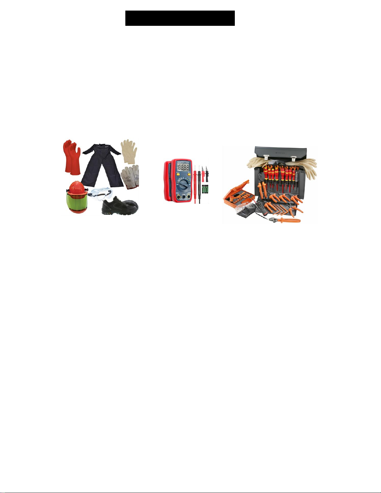
Personal Protection Equipment
Ensure that an approved PPE equipment is available to anyone working on the vehicle.
•High Voltage Insulated glasses or face shields
•High Voltage (rubber) gloves with protective (leather) outer gloves
•Insulated tools for use on high Voltage equipment
•Insulating equipment covers (to prevent unintended contact with covered surfaces)
•Insulating bags (t capture hazardous material if necessary
PPE Inspection
Users of PPE must check all protective wear for deterioration or damage before beginning work. Do
not use any damaged PPE items
•Insulated gloves should be inspected for scratches, holes, or tears
•Insulated rubber sheet should be inspected for scratches, holes, or tears
Work Area Precautions
•Work area should be indoors. Work must be protected from rain, snow, or other substances. Ideal
conditions include air conditioning to prevent condensation from forming as a result of high humidity
•Work area floor must be dry. Do not allow rain soaked or snow-covered vehicles to enter the work
area.
•Work area must be free of airborne contaminants such as metal powders or grinding debris.
•Work area must be free of free of debris or foreign material. If necessary, use curtains, cones or
safety tape to mark cleared area. (at least 6 feet)
•Display appropriate warning sign in the work area.
4
PPE

Fire Extinguisher
•Ensure that an approved fire extinguisher is well secured under the driver’s seat, within
the driver's reach and easily accessible for first responders.
•Routinely check the fire extinguisher according to its manufacturer’s instructions.
•If the fire extinguisher has been used, it must be replaced with a new fire extinguisher or
refilled before the truck can be returned to service.
•Use type A, B, or C extinguisher. DO NOT use type D fire extinguisher on battery fires.
Fire Instructions:
During a fire, certain plastic seals can produce gases which with water form a corrosive
acid. Do not touch any fluid on the vehicle.
1. Contact firefighters.
2. Create a safety perimeter of at least 6 feet around the vehicle.
3. If possible, follow HV SHUTDOWN PROCEDURE
Environment
Pollution is a serious threat to the environment. To keep pollution to a minimum, the
following rules should be observed:
Do not dump used oil, lubricants, hydraulic fluid or coolants in drains, in sewers, in
landfills or on the ground. This is illegal. These fluids should be returned to the
designated authority or appropriate chemical waste collection company for recycling or
destruction. All used fluids should be stored separately.
Service the vehicle regularly according to the instructions and recommendations in this
manual. If component service intervals are not provided in this manual, check the truck
manufacturer’s operator’s manual.
Emergency Operation
•Proper techniques and standard protocols are essential for safety during an emergency operation
involving an electric vehicle (EV).
•Shut down procedures will vary between OEM’s and even vehicle models.
•Because EV’s can move with little or no sound, conventional methods of determining if a vehicle can be
moved under its own power will be difficult to do. Making assumptions that the vehicle is not powered
up can be dangerous.
•Always be prepared to deal with hazardous conditions when working with EV’s by wearing the proper
safely equipment. Cutting corners may put you in the hospital or worse.
5
First Responder

After a Crash or Impact
1. Verify LCD screen for HV Isolation Issue.
2. Turn off the vehicle key switch.
3. Exit the vehicle.
4. Turn off the LV disconnect switch if it can be safely accessed.
5. Check for visible battery damage while maintaining a safe distance.
Turn on procedure if no HV battery pack damage exists:
1. Turn the LV disconnect switch back to ON.
2. Turn the key to the START position.
Safety procedures if the HV battery pack is damaged.
1. Contact firefighters.
2. Create a safety perimeter of at least 2 meters around the vehicle.
3. Move to an area upwind and far enough away from the accident site to avoid breathing any
hazardous smoke or gases.
Note: Always assume that the HV battery packs could be damaged after an accident and have it
inspected by a service technician.
Warning: High Voltage (HV) Shutdown
The high voltage system on any vehicle has no parts that an owner or unauthorized service
technician can service. Under no circumstances should you attempt to perform any HV battery repair.
6
First Responder

•Until proven otherwise, ALWAYS ASSUME ALL HIGH VOLTAGE COMPONENTS ARE ENERGIZED
•Electric Vehicles are quiet. DO NOT ASSUME THE VEHICLE IS UN-POWERED.
•Always approach at a 45-degree angle to avoid being hit if the vehicle unexpectedly moves.
•Physical damage to HV batteries pack may result in the release of harmful or flammable gases.
•To prevent gas buildup the passenger's compartment must be ventilated by opening the doors, rolling
down the windows or breaking the glass.
•Block (chock) the front and back of at least one of the wheels
•Engage the parking brake
Disabling the Electric Commercial Vehicle
•If the ignition switch is accessible, turn it to the “OFF” position
•Turn the Lockout Tagout Switch to the “OFF” position.
Commercial high voltage battery boxes are designed to protect the batteries in case of a crash. If the HV
battery pack is damaged, the following should be considered.
•Lithium-ion battery materials can be toxic and/or flammable.
•Ventilation is required to prevent buildup of flammable or toxic gasses.
•Lithium-ion batteries are considered “dry-cell” so any leakage would be minimal.
•Some HV batteries packs have cooling and heating systems that use coolant like a standard
vehicle’s radiator. This fluid does not create a hazard.
•Do not handle any damaged battery components at any time after an accident.
•Be aware of any odors or irritation to the eyes, nose, throat, or skin.
•When a damaged HV battery pack is identified, look for sparks, smoke, flames, bubbling or
gurgling sounds that may cause a fire.
•In case any electrolyte does leak, spray “HF Acid Eater” onto surface. Wipe up with absorbent
paper towel. Place paper towels into plastic bag or pail with spill residue. Place sealed bags in
“universal” waste storage for proper disposal.
7
Approaching the Vehicle and Immobilization
First Responder
HV Battery Damage (Breaches)

Recommended Fire Suppression Procedures
•Use NFPA compliant firefighting PPE and SCBA.
•Class A, B, or C extinguishers may be used.
•DO NOT USE CLASS D extinguishers on battery fire. These contain metal powders that can short
circuit batteries or terminals.
•Because of the time and water requirement to extinguish a battery fire, it may be best to let it burn itself
out.
•Do not force open the battery box to apply an extinguishing agent Do not penetrate body panels with
extraction tools. You may contact a HV cable.
Warning: There are HV cables that are always energized, always assume that HV cables can
cause personal injury or even death. Never attempt to cut a HV cable for any reason.
•When the vehicle is approachable, follow the vehicle shutdown procedure.
•Keep all nonessential personal upwind of the fire. Gasses may be corrosive or toxic.
•Always treat the vehicle as energized when performing post fire handling.
Electric vehicles that are partially or completely submerged will not energize the water causing a threat of
shock. Electrified vehicles are designed with ground faults circuit interrupters and other AC protection to
eliminate this hazard.
Warning: Never remove a service discontent from a submerged vehicle.
Although the water is not energized, there is still a shock hazard if you contact any of the
exposed HV cables.
Standard Procedures for Handling vehicles in water are:
•Follow the shutdown procedure in this owner’s manual.
•If the shutdown procedure cannot be performed with the vehicle submerged, contact Dana before
removing the vehicle from the water.
8
First Responder
Electric Vehicle Submersion

Service Instructions & Warnings
High Voltage (HV) System
Note: The high voltage battery on this vehicle has no components that require service by the
user. Do not try to repair high voltage battery components, cables, or connectors. All high
voltage cables are colored orange for easy identification.
Note: If a collision occurs, do not touch any high voltage cables, connectors, or components.
Note: In the unlikely event of a fire, immediately contact your local fire emergency responders.
Warning: Do not touch or attempt to remove any orange colored high voltage cables,
connectors, or components.
Warning: The high voltage battery has no parts that an owner or unauthorized service
technician can service. Under no circumstances should you open or tamper with the battery or
other HV components. Always contact a certified service dealer.
Caution: The HV battery requires no owner maintenance. If you get a battery check light,
contact a PACCAR service dealer.
Warning: Repair of HV components or the HV battery is very dangerous and could cause
severe burns and electric shock. Never remove or disassemble any HV components in this
vehicle. Dana recommends that all inspections and repairs be conducted by an authorized and
trained service dealer.
Warning: DO NOT cut into or remove any of the orange high voltage cables. Refer to the OEM
specific location of chassis mounted component.
Warning: DO NOT cut into or open any electric motors, the DC/DC converter, HV inverters, HV
chargers, HV battery packs or controllers. These components are non-serviceable and should
only be replaced if service is required
Welding
Caution: Dana’s warranty does not cover damage to electrical components
caused by any type of welding. Electrical components closer than 12” from the
welding site must be removed from the vehicle.
Warning: Prior to performing any maintenance on the electric vehicle, always perform the HV
voltage shutdown procedure.
Warning: High Voltage Shutdown
The high voltage system on this vehicle has no parts that an owner or unauthorized service
technician can service. Under no circumstances should you attempt to perform any part of this
procedure. This procedure should only be performed by a trained and certified service provider.
9
Service Warnings

HV Battery Charging
Warning: Never spray liquid at high pressure towards the charging port while charging. Failure to follow these
instructions can result in serious injury or damage to the vehicle, charging equipment or property.
Caution: Make sure to use a designated charger when charging the HV battery. Using different types of
chargers may have serious effect on the vehicle’s durability.
Follow the instructions below to charge the vehicle batteries when not in use.
Important Note: The procedure below is an example of just one charging inlet system you may encounter.
Always follow the procedure for that individual system.
Charging Procedure
1. Turn off the vehicle and remove the ignition key.
2. Open the charging port cover.
3. Connect the charger plug to the charger socket, a WHITE light will illuminate.
4. A single ‘chirp’ will be heard, inside the cabin.
5. The system will run a self-check and activate.
6. A double ‘chirp’ will be heard, the display will show Ready, and the inlet will go GREEN.
7. Depress grey button on the top of the inlet connector to plug in the coupler
8. When the green light begins blinking, the vehicle is charging.
9. A blinking red light indicates a charging error.
10. A steady green light means the charge is complete.
10
HV Battery Charging

HV Chassis Shut Down Procedure
Caution: Vehicle maintenance, other than routine
operator maintenance should be performed by a
certified, trained mechanic. Many maintenance
procedures require special certification, training, and
tools to be done safely. Attempting to perform
maintenance procedures without proper training and
equipment may lead to serious injury or death.
Important Note: It is critical that you follow all the
OEM’s HV shutdown procedures before you start a
repair. The danger of electrocution is real and must
be your number one priority when repairing any HV
vehicle.
Warning: Do not touch or attempt to remove any
orange-colored high voltage cables, connectors, or
components until the high voltage system has been
shut down/de-energized.
Warning: Repair of HV components or the HV
battery is very dangerous and could cause severe
burns and electric shock. Never remove or
disassemble any HV components in this vehicle. All
inspections and repairs must be conducted by a
certified and trained mechanic.
Warning: Some HV cables are always energized
even after the HV shutdown procedure. Always
assume that HV cables can cause personal injury or
even death. Never attempt to cut a HV cable for any
reason.
Important Note: PACCAR uses high voltage
batteries of up to 700V DC which is very hazardous
if handled
carelessly. All Batteries should be properly and
safely
de-energized prior to conducting any electrical work
on the vehicle to avoid serious injury or death.
3 Levels of Shutdown/De-Energization
Procedures
Fig A –Potential High Voltage path with 12V TURNED OFF
with MSD’s INSERTED
Fig B –Potential High Voltage path with 12V TURNED OFF
with S-BOX MSD’s REMOVED
Fig C –Potential High Voltage path with 12V TURNED OFF
with S-BOX and BATTERY PACK MSDs REMOVED
11
12V LOTO
General Vehicle Maintenance
Fluid Top-offs, Inspections, Tire Rotation
Group "A" MSD (Includes 12V Shut Down LOTO)
Any Operation with Dana HVComponenets, Except HV Battery System
Any Operation with Dana HVCables, Except HV Battery System
Diagnostic or Opening of HVJuction Box
Group "B" MSD (Includes 12V Shut Down LOTO & Group "A" MSD)
Any Operation touching the HVBattery System Including:
S-box
HV Battery Cables
Battery Packs
HV Chassis Shut Down Procedure
Live High Voltage
Components Shut Down

Caution: Removing the Battery Pack MSDs DOES
NOT De-Energize the Battery Packs. They remain
charged and should be treated as hazardous if
handled incorrectly.
12V Shutdown and LOTO Procedure
1. Turn off vehicle and remove the key from the
ignition.
2. Create a six-foot or 2m barrier around the vehicle.
3. Wear high voltage gloves, safety glasses / shield
and EH rated work boots rated 12 Calories / cm².
4. Properly insulated tools are required to safely
perform battery related tasks.
5. Secure the vehicle by placing wheel chucks under
the front wheels to prevent vehicle from
accidentally rolling.
6. Locate the 12V/24V Master Disconnect Switch
located on the right side behind the cabin.
7. Turn the switch to the off position and install a
lockout tag and pad lock.
ON POSITION OFF POSITION
Two types of lockouts are possible:
a. Simple lockout: When only one person works on
the truck, the switch must be turned to OFF and a
padlock must be installed on the switch to protect
against electric shock and protect the truck
against any short circuit.
b. Group lockout: When several people work on
the truck at the same time and each performs a
different job, each person must then lock out the
energy source
Warning: To perform any service and
maintenance
operations involving High Voltage DANA BEV
powertrain components except battery packs,
removal of MSDs from the S-BOX is required.
This includes replacement of any HV component,
HV wire harness, opening of HV JCT Box,
diagnostics and debugging of HV componentry.
12
HV Chassis Shut Down Procedure

GROUP “A” S-BOX MSD DE-ENERGIZING
PROCEDURE
1. Turn off vehicle and remove the key from the
ignition.
2. Create a six-foot or 2m barrier around the vehicle.
3. Wear high voltage gloves, safety glasses / shield
and EH rated work boots rated 12 Calories / cm².
4. Properly insulated tools are required to safely
perform battery related tasks.
5. Secure the vehicle by placing wheel chucks under
the front wheels to prevent vehicle from
accidentally rolling.
6. Locate the 12V/24V Master Disconnect
Switchlocated on the right side behind the cabin.
7. Turn the switch to the off position and install a
lockout tag and pad lock.
ON POSITION OFF POSITION
8. Locate the S-BOX, and remove all MSDs (1 or 2,
depending on system)
13
HV Chassis Shut Down Procedure

9. Wearing class 0 insulated gloves and leather
protective gloves, Remove the MSDs (Manual
Service Disconnect) from the S-BOX by
compressing the buckle tab and rotating the
handle 90 degrees.
Warning: When required, wear the properly rated
arc-rated shirt and pants or coveralls, face shield,
and balaclava.
10. To Disassemble the MSD, press the buckle (A),
pull the MSD handle in the direction of arrow (B) (
<90°)
11. Press the buckle (A), pull the MSD plug in the
direction of arrow (B), perpendicularly pull the
handle from the MSD base.
12. Wait 5 minutes after the al MSDs are removed to
let the HV capacitors discharge.
13. Place MSDs with the key from the lockout of the
12/24 volt disconnect in a group lock box.
14. For safety, the junction box has two “safety
screws” that connects the cover to the box. These
screws can not be removed until you disconnect
the high voltage batteries and inlet charger cables.
See images below.
15. Remove the top cover bolts and then the junction
box cover.
16. Use a Cat-IV 1000V rated DVM and insulated
shank probes to verify all voltage measurements.
17. To ensure the meter is working properly, measure
the voltage between the 12V battery terminals to
obtain a 12V DC reading.
14
HV Chassis Shut Down Procedure

18. Probe between (+ and -) Test Points 1, 2 and 3 busses
with a Class IV multimeter to make sure the voltage
readings are less than < 5 Volts.
19. If the voltages measured are greater than >5V wait for
another 5 min. to drain.
20. If the voltages measured are less than <5V it is now
safe to perform system repairs.
21. After measuring voltages, test the DVM once again to
ensure the meter is working properly, measure the
voltage between the 12V battery terminals to obtain a
12V DC reading.
GROUP “B” HV BATTERY PACK MSD
DE-ENERGIZING PROCEDURE
Warning: To perform any service and maintenance
operations involving High Voltage S-BOX, battery
cabling,
removal of MSDs from the Battery Pack is required.
Caution: Removing the Battery Pack MSD DOES
NOT De-Energize the Battery Packs. They remain
Charged and should be treated as Hazardous if
handled incorrectly.
1. Turn off vehicle and remove the key from the
ignition.
2. Create a six-foot or 2m barrier around the vehicle.
3. Wear high voltage gloves, safety glasses / shield
and EH rated work boots rated 12 Calories / cm².
4. Properly insulated tools are required to safely
perform battery related tasks.
15
TP 1 (+)
TP 1 (-)
Test Point # 1
HV Chassis Shut Down Procedure
TP 3 (+)
TP 3 (-)
Test Point # 3
TP 2 (+)
TP 2 (-)
Test Point # 2

5. Secure the vehicle by placing wheel chucks under the
front wheels to prevent vehicle from accidentally
rolling.
6. Locate the 12V/24V Master Disconnect Switchlocated
on the right side behind the cabin.
7. Turn the switch to the off position and install a lockout
tag and pad lock.
ON POSITION OFF POSITION
8.
9. Locate the S-BOX, and remove all MSDs (1 or 2,
depending on system)
10. Wearing class 0 insulated gloves and leather
protective gloves, Remove the MSDs (Manual
Service Disconnect) from the S-BOX by
compressing the buckle tab and rotating the handle
90 degrees.
Warning: When required, wear the properly rated
arc-rated shirt and pants or coveralls, face shield,
and balaclava.
11. To Disassemble the MSD, press the buckle (A),
pull the MSD handle in the direction of arrow (B) (
<90°)
12. Press the buckle (A), pull the MSD plug in the
direction of arrow (B), perpendicularly pull the
handle from the MSD base.
13. Wait 5 minutes after the al MSDs are removed to
let the HV capacitors discharge.
14. Place MSDs with the key from the lockout of the
12/24 volt disconnect in a group lock box.
16
HV Chassis Shut Down Procedure

14. For safety, the junction box has two “safety screws”
that connects the cover to the box. These screws
can not be removed until you disconnect the high
voltage batteries and inlet charger cables. See
images below.
15. Remove cover fasteners and remove the junction
box cover.
16. Use a Cat-IV 1000V rated DVM and insulated
shank probes to verify all voltage measurements.
17. To ensure the meter is working properly, measure
the voltage between the 12v battery terminals to
obtain a 12V DC reading.
18. Probe between (+ and -) Test Points 1, 2 and 3
busses with a Class IV multimeter to make sure the
voltage readings are less than < 5 Volts.
19. If the voltages measured are greater than >5V wait
for another 5min. to drain.
20. If the voltages measured are less than <5V it is
now
safe to perform system repairs.
21. After measuring voltages, test the DVM once again
to ensure the meter is working properly, measure
the voltage between the 12V battery terminals to
obtain a 12V DC reading.
17
TP 1 (+)
TP 1 (-)
Test Point # 1
TP 2 (+)
TP 2 (-)
Test Point # 2
TP 3 (+)
TP 3 (-)
Test Point # 3
HV Chassis Shut Down Procedure

22. Now locate the MSDs on the battery packs
23. Remove the forward access cover from both
battery boxes.
24. Loosen the 6 fasteners holding the MSD to the
HV battery pack.
25. Wearing class 0 insulated gloves and leather
protective gloves, Remove the Fuse / MSD
(Manual Service Disconnect) from the HV battery.
Warning: When required, wear the properly rated
arc-rated shirt and pants or coveralls, face shield,
and balaclava.
Important Note: Battery MSDs are very tight &
difficult to remove. Plastic tools may be used as a
wedge or pry tool.
DO NOT USE METALTOOLS
26. These MSD’s must be put into a lock out box.
27. A safety cover must be installed over the MSD
outlet on the battery pack once an MSD is
removed.
28. The S-box input and output terminals can be
used to ensure the s-box is de-energized but not
the battery packs.
29. It is not possible to de-energize batteries for
disassembly.
Warning: The MSD only disconnects the positive
terminal. THE NEGATIVE TERMINAL AND CABLE
ARE LIVE DURING DISASSEMBLY.
18
HV Chassis Shut Down Procedure

30. Measure directly across the battery pack HV
terminals (pack+/pack-), or if the s-box HV input
connectors (batt+/batt-) are disconnected it can
be measured across the HV plug terminals (cable
side, not receptacle).
Battery lug image with cover removed
Measure from battery Positive to Negative
31. If the voltages measured is greater than >5V wait
for another 5 min. to drain.
32. If the voltages measured is less than <5V it is
now safe to perform system repairs.
33. After measuring voltages, test the DVM once
again to ensure the meter is working properly,
measure the voltage between the 12V battery
terminals to obtain a 12V DC reading.
Important Note: When replacing HV battery
packs and the HV cables need to be
disconnected, always follow Dana’s HV battery
replacement procedure. This procedure can be
found in the OEM chassis service manuals.
19
TP 1 (+)
TP 1 (-)
Test Points # 1, # 2
TP 2 (+)
TP 2 (-)
HV Chassis Shut Down Procedure
Table of contents
Popular Camera Accessories manuals by other brands

H2O Audio
H2O Audio iFP-700 owner's manual

Costar Video Systems
Costar Video Systems CDMWMA installation manual

Inventus Power
Inventus Power PROTRXion M-48V60-TRX-HD quick start guide

PROAIM
PROAIM CINEMA Series instruction manual

Panasonic
Panasonic LUMIX DMW-MCTZ7 operating instructions

Camtree
Camtree HUNT instruction manual