Spida Machinery Fast Framer Manual
OPERATION & MAINTENANCE
MANUAL

1 Operations Manual –Gen III Fast Framer (Frame Nailer)
Serial Plates
All enquiries should be directed to:
SM2012 Ltd - Known as Spida Machinery
Australia free phone 1800 146 110
America free phone 1888 262 9476
NZ free phone 0800 SPIDAS or +64 7 579 5010
Below is a copy of the serial plate displayed on the back of the machine
WARNING
This machine must only be used by personnel who have been
properly instructed in all aspects of the machine’s safe operation.
Operators must also wear the recommended personal protective
equipment and have thoroughly read and understood this manual.

2 Operations Manual –Gen III Fast Framer (Frame Nailer)
1Contents
2 Overview .........................................................................................................................................7
3 Specifications ..................................................................................................................................7
4 Installation ......................................................................................................................................8
4.1 Handling & Transport..............................................................................................................8
4.2 Installation ..............................................................................................................................8
5 Safety ............................................................................................................................................10
5.1 Young Persons.......................................................................................................................10
5.2 Long Hair and Loose clothing................................................................................................10
5.3 Cleaning and Maintenance of Machinery.............................................................................10
5.4 Training and Supervision of Frame Nailer Operators ...........................................................10
5.5 Responsibilities of Frame Nailer Operators..........................................................................10
5.6 Operating Speeds and Vibration...........................................................................................11
5.7 Machinery Stability and Location..........................................................................................11
5.8 Electrical Safety.....................................................................................................................11
5.9 Isolation, hold cards and lock out devices ............................................................................11
5.10 Noise control.........................................................................................................................12
5.11 Manual Handling...................................................................................................................12
5.12 Recommended Service Interval ............................................................................................12
6 Safe Operation ..............................................................................................................................13
6.1 User Warnings.......................................................................................................................13
6.2 Manual Handling...................................................................................................................14
6.3 General..................................................................................................................................15
6.4 Operation..............................................................................................................................16
6.5 Maintenance .........................................................................................................................17
6.6 Recommendations ................................................................................................................18
7 Operating Controls........................................................................................................................19
7.1 Frame Nailer controls............................................................................................................19
7.2 Pneumatic Controls...............................................................................................................21
7.3 Pneumatic filter/regulator....................................................................................................23
8 Operation......................................................................................................................................24
8.1 Machine Set-up........................................................................ Error! Bookmark not defined.
8.2 Stations Right/Left/or Both...................................................... Error! Bookmark not defined.
8.3 Guns Top/Bottom/or Both....................................................... Error! Bookmark not defined.
8.4 Guns in correct position........................................................... Error! Bookmark not defined.

3 Operations Manual –Gen III Fast Framer (Frame Nailer)
8.5 Trolley and Carriage Clamps .................................................................................................25
8.6 Loading..................................................................................... Error! Bookmark not defined.
8.7 Clamping and Firing Operation ................................................ Error! Bookmark not defined.
8.8 Air Dump .................................................................................. Error! Bookmark not defined.
8.9 Machine Shut-down................................................................. Error! Bookmark not defined.
9 Parts Identification........................................................................................................................28
9.1 Top Level Assembly (2001000) .............................................................................................28
9.2 Main Frame Assembly (1701100) .........................................................................................30
9.3 Nog Trolley Assembly (1701660) ..........................................................................................32
9.4 Fixed Carriage Assembly (1701200 L or R)............................................................................34
9.4.1 Exploded Horizontal Stud Clamp Assembly (1701130).................................................36
9.5 Floating Carriage Assembly (1701200 L or R) .......................................................................38
9.6 Plate Clamp Assembly (2001200 L or R - B) ..........................................................................40
9.7 Gun Mount Assembly (SMPGMA02).....................................................................................42
9.8 Computer Monitor and Electrical Enclosure Assemblies (0605000 and EEHW) ..................44
9.9 Progressor Tables (1804420) ................................................................................................45
9.9.1 Fence Assembly (SMPGPFA6300) .................................................................................47
9.9.2 Gearbox Kit 2 (SMPGPGK2)...........................................................................................49
9.9.3 Guide Profile Trolley Kit (SMPGPTK2) ...........................................................................50
10 Maintenance .............................................................................................................................51
10.1 Maintenance Items ...............................................................................................................52
10.1.1 Guards...........................................................................................................................52
10.1.2 Air Line Lubrication .......................................................................................................52
10.1.3 Keep work area clear ....................................................................................................52
10.1.4 Inspect Clamps ..............................................................................................................52
10.1.5 Plate Sensor ..................................................................................................................53
10.1.6 Clean Frame Nailer of any build up...............................................................................53
10.1.7 Noises or vibrations ......................................................................................................53
10.1.8 Emergency Stop Buttons...............................................................................................53
10.1.9 Dry Air Supply................................................................................................................54
10.1.10 Air Supply ..................................................................................................................54
10.1.11 Check Filter/Regulator ..............................................................................................54
10.1.12 Nog Trolley Assemblies.............................................................................................54
10.1.13 Carriage Assemblies ..................................................................................................54
10.1.14 Loose Fasteners and Fixings......................................................................................55

4 Operations Manual –Gen III Fast Framer (Frame Nailer)
10.1.15 Guide Trolley Slides...................................................................................................55
10.1.16 Bench Top .................................................................................................................55
10.1.17 Maintain Brake Materials..........................................................................................55
10.1.18 Maintain Frame Nailer ..............................................................................................55
10.1.19 Nail Guns...................................................................................................................55
10.2 Replacing Guide Trolley Slides ..............................................................................................56
10.2.1 Reference Distances for Guide Trolley sliders ..............................................................57
11 Foreseeable Misuse ..................................................................................................................58
12 Trouble Shooting.......................................................................................................................59
13 Distributor & Repairer Contacts................................................................................................60
13.1 Agent/Distributor..................................................................................................................60
13.2 Automation Repairs ..............................................................................................................60
13.3 Mechanical Repairs...............................................................................................................60
14 Warranty ...................................................................................................................................61
15 Pneumatic Drawings .................................................................................................................63
16 Training Certificate....................................................................................................................64
17 Frame Nailer Training Check List...............................................................................................65

5 Operations Manual –Gen III Fast Framer (Frame Nailer)
Tables
Table 1, Frame Nailer Specifications.......................................................................................................7
Table 2, General Hazards ......................................................................................................................15
Table 3, Operational Hazards................................................................................................................16
Table 4, Maintenance Hazards..............................................................................................................17
Table 5, Control functions (see Figure 2)..............................................................................................20
Table 6, Pneumatic Control functions (see Figure 3)............................................................................22
Table 7, Valve/Filter/Regulator/Dump parts ........................................................................................23
Table 8, Parts List –Frame Nailer .........................................................................................................29
Table 9, Main Frame Assembly parts list..............................................................................................31
Table 10, Nog Trolley Assembly parts list .............................................................................................33
Table 11, Fixed Carriage Assembly parts list.........................................................................................35
Table 12, Exploded Horizontal Stud Clamp Assembly parts list............................................................37
Table 13, Floating Carriage Assembly parts list ....................................................................................39
Table 14, Plate Clamp Assembly parts list ............................................................................................41
Table 15, Gun Mount Assembly parts list.............................................................................................43
Table 16, Computer Monitor and Electrical Enclosure Assemblies Parts List ......................................44
Table 17, Progressor Table Assembly Parts List....................................................................................46
Table 18, Fence Assembly Parts List .....................................................................................................48
Table 19, Gearbox Motor Assembly Parts List......................................................................................49
Table 20, Guide Profile Trolley Assembly Parts List..............................................................................50
Table 21, Maintenance intervals...........................................................................................................51
Table 22, Common misuse issues .........................................................................................................58
Table 23, Trouble shooting ...................................................................................................................59

6 Operations Manual –Gen III Fast Framer (Frame Nailer)
Figures
Figure 1, Recommended exclusion zone around the Frame Nailer......................................................11
Figure 2, Frame Nailer controls.............................................................................................................19
Figure 3, Frame Nailer pneumatic controls ..........................................................................................21
Figure 4, Valve/Filter/Regulator/Dump assembly ................................................................................23
Figure 5, Nog centres adjustment.........................................................................................................25
Figure 6, Frame Nailer with guns. .........................................................................................................28
Figure 7, Main Frame Assembly............................................................................................................30
Figure 8, Nog Trolley Assembly.............................................................................................................32
Figure 9, Fixed Carriage Assembly ........................................................................................................34
Figure 10, Exploded Horizontal Stud Clamp Assembly .........................................................................36
Figure 11, Floating Carriage Assembly..................................................................................................38
Figure 12, Plate Clamp Assembly..........................................................................................................40
Figure 13, Gun Mount Assembly...........................................................................................................42
Figure 14, Computer Monitor and Electrical Enclosure Assemblies.....................................................44
Figure 15, Progressor Table Assembly..................................................................................................45
Figure 16, Fence Assembly....................................................................................................................47
Figure 17, Gearbox Motor Assembly ....................................................................................................49
Figure 18, Guide Profile Trolley Assembly ............................................................................................50
Figure 19, Plate Sensor locations..........................................................................................................53
Figure 20, Trolley slide replacement.....................................................................................................56
Figure 21, Stop Slider distances ............................................................................................................57
Figure 22, Pneumatic diagram ..............................................................................................................63

7 Operations Manual –Gen III Fast Framer (Frame Nailer)
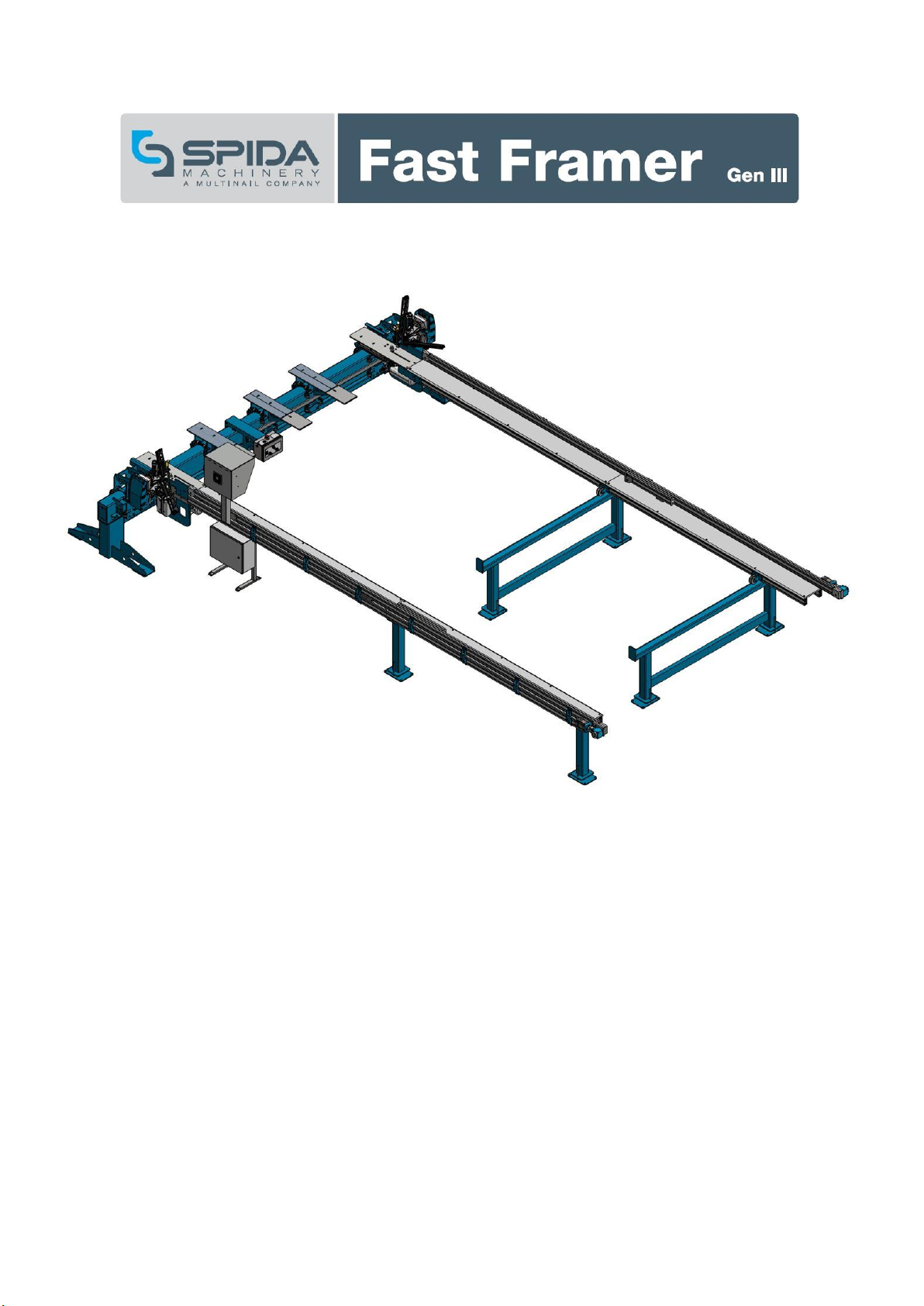
2Overview
The Spida Gen III Fast Framer (heretofore referred to as the Frame Nailer) is designed to accurately
nail timber frames, using pneumatically operated nail guns.
The Frame Nailer must be used per the standard operating procedures set out in this manual. Any
actions carried out which are not contained in this manual are not endorsed by Spida Machinery and
cannot be warranted.
All operators should read and then sign the register of this manual before operating the Frame
Nailer to ensure they are thoroughly familiar with the machine capabilities, limitations and to ensure
correct operating procedures are adhered too.
Only those operators that have received training on the correct operation of the Frame Nailer are
deemed competent and qualifies to operate the machine.
The Frame Nailer test procedures must be performed at installation and after any maintenance,
adjustment, repair or modification of the machine. The test procedure is available on request.
The competent operator must also regularly perform the recommended maintenance procedures
and checks detailed in this manual.
All pneumatic lines must be set as to not allow its movement through the nailing area of adjacent
machinery.
This manual offers many safety tips, but its purpose is not to provide instruction in all the skills and
techniques required to manufacture timber frames safety and efficiently.
Due to improvements in design and performance during production, in some cases there may be
minor discrepancies between the actual machine and the illustrations and text in this manual.
3Specifications
Table 1, Frame Nailer Specifications
Overall Width
4975 mm
Overall Height
1410 mm
Overall Length
1345 mm
Working Height
870 mm
Weight
765 kg
Timber Feed
Front
Air Supply
6-8 Bar (600-800 kPa)
Nail Gun Capacity
273.8 l/min (60 cycles) each
Specifications may change without notice

8 Operations Manual –Gen III Fast Framer (Frame Nailer)
4Installation
4.1 Handling & Transport
•Box all additional parts and secure with the machine
•Using a single fork truck, lift the machine package underneath using the forklift spaces
provided
•Once on the truck, tightly strap the machine.
•Do not place any loads on top of the machine
•The machine should be kept free from road grime and rain, and should be covered at all
times while being transported
The Frame Nailer will be delivered in large component form and will require assembly on site by
trained personnel. Due care and attention should be given whilst unpacking the components from
their packaging materials. Any damage caused whilst in transit should be noted immediately and
Spida Machinery informed. Refer to section 3 specifications for weights of individual components
when selecting Manual Handling Equipment required, prior to positioning them on the selected site.
4.2 Installation
•It is advisable to forklift the machine package as close to the final assembly point as possible
to reduce manual lifting
•The final operating position of the machine must be free from any rubbish or impediments
•There must be good lighting in the installation area to allow proper positioning of the
machine
•The ground on which the machine rests must not vary by more than 30mm over a 12m x 5m
area
•The Frame Nailer should be leveled using jacking bolts on steel jacking plates. Once level,
machine should be bolted to the floor through holes provided.
•Electrical commissioning to be to local standards and be performed by a qualified electrician
The site selected for the Frame Nailer will depend on the ground. The ground chosen should be
clean and free of water or possible flooding. The area on which the framework sits must be as even
and horizontal as possible. This can be achieved by adjusting the length of the feet. There should be
no twist to the framework once the feet have been adjusted to take the ground
into account.
The final operating position of the machine should be free of all rubbish or impediments, with
general access to all areas of the Frame Nailer for the ease of loading and unloading material of
varying sizes.
With the machine in position, a qualified engineer should be used to connect the pneumatic
components to the machine and adjust the air pressure to the required setting (refer to 3
Specifications for pressure settings)

9 Operations Manual –Gen III Fast Framer (Frame Nailer)
Check all pneumatic hoses and connectors to ensure that the fittings haven’t worked loose during
transportation of the machine. Re-tighten all fittings that appear to be leaking. If leaking persists
undo the fittings and apply a sealing compound to the joints in question. Re-tighten the fitting. (Any
serious leaking problems during the warranty period should be reported to Spida Machinery). Check
the air pressure in the system is sufficient to operate the machine (refer to 3 Specifications for
pressure settings).
To check the air pressure, turn the compressor on and allow the pressure to build up. When the
controls are activated, normal pressure should read 6-8 bar or 600- 800 kPa. All maximum pressures
are factory set and should not be changed.
Check that all safety equipment is functioning properly.

10 Operations Manual –Gen III Fast Framer (Frame Nailer)
5Safety
This section is provided as a guide only, it is the responsibility of the employer to ensure compliance
with the relevant Health and Safety Regulations applicable to them at the time.
5.1 Young Persons
No person under the age of 15 should be allowed to operate or assist with the operation of
machinery.
5.2 Long Hair and Loose clothing
Any long hair or loose clothing must be fully contained to eliminate the risk of entanglement with
machinery.
PROTECTIVE SAFETY CLOTHING AND EQUIPMENT MUST BE WORN; INCLUDING:
Eyewear
Hearing protection
Respirator or Dust mask
Protective Clothing
Safety footwear
5.3 Cleaning and Maintenance of Machinery
For safe and reliable use, machinery should be regularly cleaned and maintained. During cleaning
and maintenance, the Frame Nailer must be isolated from all sources of energy and locked out to
prevent unexpected operation.
5.4 Training and Supervision of Frame Nailer Operators
No person should be expected or allowed to operate the Frame Nailer until they have been fully
trained and authorised to do so. They must be familiar with:
•Actual and potential hazards and appropriate controls.
•Correct use and adjustment of guards.
•Emergency procedures.
•How the Frame Nailer works.
•Checks to perform prior to starting.
•How to recognise potential faults.
•Location of controls and how to Stop and Start the Frame Nailer.
5.5 Responsibilities of Frame Nailer Operators
Operators should:
•Check the Frame Nailer prior to use and during operation to ensure it is in sound operating
order.
•Report immediately any defects noted to their supervisor.
•Use any, and all safety equipment provided.
•Not operate any machinery if under the influence of drugs or alcohol, consult a physician or
pharmacist if unsure of any medication.
11 Operations Manual –Gen III Fast Framer (Frame Nailer)
5.6 Operating Speeds and Vibration
Machinery should be operated within its designed limitations and for its designed use only, any
unfamiliar noise, vibration or failure should be investigated and remedied promptly.
5.7 Machinery Stability and Location
The Frame Nailer should be securely fastened to the structure of the building to prevent movement
or toppling over. Location should provide access all around for maintenance and cleaning. Lighting
must be adequate to allow operator to clearly see controls and work pieces but not glaring or
blinding.
Consideration should be given to the operators work area for product flow and to minimise
repetitive actions and unnecessary movement.
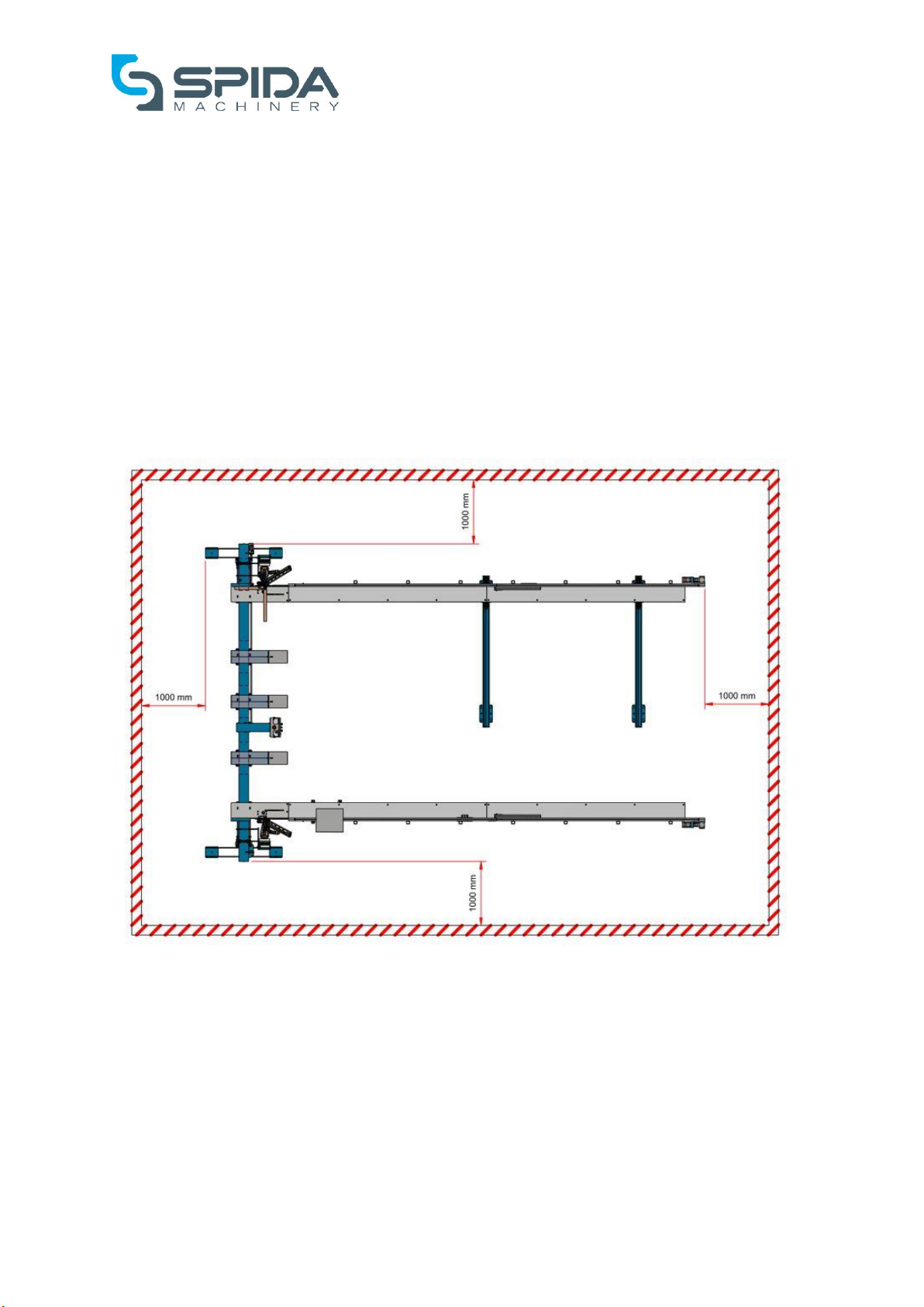
An exclusion zone around the Frame Nailer should be maintained to prevent persons not directly
involved with the operation of the machine from reaching any part of the machine.
Figure 1, Recommended exclusion zone around the Frame Nailer.
5.8 Electrical Safety
Electrical wiring must be installed and maintained by a suitably qualified person in accordance with
relevant regulations.
5.9 Isolation, hold cards and lock out devices
There should be procedures for isolating and locking out the Frame Nailer, for purposes of
maintenance and to prevent unintended use should a fault have been identified.

12 Operations Manual –Gen III Fast Framer (Frame Nailer)
5.10 Noise control
The normal operation noise of some machines will be more than permitted noise exposure levels.
Employers must ensure adequate hearing protection is available and is used by all persons in the
affected area.
5.11 Manual Handling
Manual handling should be avoided where possible, use of mechanical lifting and assisting
equipment is recommended. Consider using forklifts, hoists, and trolleys to eliminate lifting and
carrying components.
5.12 Recommended Service Interval
It is recommended that for optimal performance, the Frame Nailer should be serviced every 6
months.
It is also recommended that a service log be kept, as a reminder of when the next service should be
due. Spida Machinery performs service runs on a regular basis throughout NZ; however, should the
need arise for an early service, or should a service need to be booked in advance, please advise
Spida Machinery accordingly.
WARNING! Do not operate the Frame Nailer without having received the proper
instruction in operation and safety from this manual.
WARNING! It is recommended that the employers maintain training records
demonstrating the competencies of each employee

13 Operations Manual –Gen III Fast Framer (Frame Nailer)
6Safe Operation
NOTE: The Frame Nailer is to be operated in accordance with this manual. Deviation from this
specified operation may result in incorrect nailing, measuring or injury.
6.1 User Warnings
•All moveable parts of the machinery must be set so as not to allow its movement through
the cutting/pressing area of adjacent machinery.
•All machine and components should be inspected upon delivery and at weekly intervals for
looseness, fracture, bends, sharp edges or surfaces and any other condition that may
contribute to a human mishap or further deterioration of the machine. We suggest a log be
kept for this purpose.
•When broken, damaged, or loose parts (or any condition that may represent a hazard) are
observed, corrective action should be taken immediately. Inadequate attention to maintain
the machine can cause the premature failure of these parts. We suggest this information also
be logged.
•The electrical boxes should be locked at all times to avoid casual entry by unauthorized
persons, as touching live surfaces is hazardous.
•Split, broken, warped, twisted or material with excessive wane should be avoided or used with
caution because of the greater possibility of the material not being held securely during
manufacturing processes.
•The machine is not to be used for any other purpose than the nailing of timber components.
•Keep hands out of moving parts on the machine. Operators should be instructed not to extend
fingers or limbs into or beyond the vicinity of the warning labels. The danger here is obvious
–fingers in these areas will risk mutilation.
•Be sure the machine is completely free of foreign objects, and that all guards are in place
before connection to electrical and/or pneumatic supply.
•Any guards removed for maintenance or adjustments must be replaced before the machine
is put back into service.
•Exceeding the capabilities of the machine will void the warranty and could lead to a serious
injury.
•All Operators should read and then sign the register of this manual before operating the
Frame Nailer to ensure they are thoroughly familiar with the machine capabilities and
limitations and to ensure correct operating procedures are adhered to.
•Failure to perform the daily and weekly service checks as per the schedule may result in
serious machine damage or a severe accident.
WARNING! This machine must only be operated by personnel who have been
properly instructed in all aspects of the machine’s safe operation. They must also
be wearing the recommended protective clothing and have thoroughly read and
understood this operation and service manual.

14 Operations Manual –Gen III Fast Framer (Frame Nailer)
6.2 Manual Handling
The following is not a comprehensive list. Manual lifting has the potential to be hazardous; so, for a
full description of material handling please refer to lifting standards, techniques, and your own
company policies.
•Ensure material supply is via forklift or other support mechanism
•Ensure correct lifting techniques are adopted to transfer material to infeed of cutting line
•Suggest use of trolleys or bench at required height and location to minimize handling and
twisting
•Ensure required PPE is worn
•Ensure correct and appropriate lifting techniques are used
•Suggest the setup of a material supply via gravity roller transfer system
•Avoid twisting torso when moving pre-cut members from transfer system to pressing
surface of table
•Only lift components of weight which you assess to be within your limit
•Use machinery (forklift) for material decreed to be too heavy or ask for assistance from
another worker

15 Operations Manual –Gen III Fast Framer (Frame Nailer)
6.3 General
Table 2, General Hazards
POTENTIAL HAZARDS
SAFE WORK PROCEDURE
Safety
Ask questions if you have any doubts about doing the work safely.
Check and adjust all safety devices daily.
Poor Guarding
Ensure all guards are fitted correctly and are adequately guarding
guns and moving parts. Make sure guards are in position and in
good working order. Do not operate machine without guards.
Poor Housekeeping
Inspect Frame Nailer and surrounding areas for obstructions,
hazards, and defects. Remove built-up debris from around
machine, electrical leads, pneumatic lines, and power points.
Electrical Faults
Inspect electrical leads for damage.
Inoperable Safety Switches
Check that start/stop and emergency stop buttons operate
effectively.
Incorrect Accessories
Use only the accessories designed for each specific application
Foreign Objects
Check that foreign objects and maintenance tools etc. are
removed from the machine before using the machine.
Defective/Damaged parts
Any identified defects must be reported and actioned prior to use
of the Frame Nailer.
WARNING! This machine must only be operated by personnel who have been
properly instructed in all aspects of the machine’s safe operation. They must also
be wearing the recommended protective clothing and have thoroughly read and
understood this operation and service manual.

16 Operations Manual –Gen III Fast Framer (Frame Nailer)
6.4 Operation
Table 3, Operational Hazards
POTENTIAL HAZARDS
SAFE WORK PROCEDURE
Slip, Trip & Falls
Avoid awkward operations and hand positions where a sudden slip could
cause your hand or part of your body to move into the nailing line. Electric
power cords should be above head level or in the floor in such a way that
they are not trip hazards. Floor areas should be level and non-slip. Clean up
any spills immediately.
Workplace
Use good lighting so that the work piece and machine controls can be seen
clearly. Position or shade light sources so they do not shine in the operators’
eyes or cause glare and reflections. Ensure that the floor space around the
equipment is sufficient to allow the operator to process his work without
bumping into other staff or equipment. Keep the work area free of clutter,
clean, well swept and well lit.
Housekeeping
Clean built up debris from around the machine, electrical leads, pneumatic
lines, and power points
Defects
Report all defects to the supervisor
Personal Protection
Wear safety glasses or a face shield. Wear hearing protection that is suitable
for the level and frequency of the noise you are exposed to in the work area.
Wear dust masks when required. Do not wear gloves when operating this
machine. Do not wear loose clothing, work gloves, neckties, rings, bracelets
or other jewellery that can become entangled with moving parts
Machine Guarding
Make sure all guards are fastened in position. The machine MUST NOT be
operated with any of the guards removed. The machine is fitted with steel
guards.
Improper Use
Only use the machine for what it has been designed for.
Material Defects
Inspect stock for nails or other foreign materials before nailing. Use only
material that the machine has been designed to accommodate.
Operator Technique
Do not impede the movement of the Frame Nailer while in use. Ensure any
body parts, clothing, or work tools do not get in the way of moving parts.
Only place material once the Frame Nailer is in the home position and has
come to a complete halt. Do not move stock from the Nail table until the
clamps have been returned to their home position.
Hit by projectiles
The Frame Nailer must be electrically and pneumatically isolated before
attempting to clear blockages or material jams. Any small off cut should be
removed using a push stick which has been properly constructed. Do not use
fingers to remove items which have become entangled in movable parts.
WARNING! This machine must only be operated by personnel who have been
properly instructed in all aspects of the machine’s safe operation. They must also
be wearing the recommended protective clothing and have thoroughly read and
understood this operation and service manual.

17 Operations Manual –Gen III Fast Framer (Frame Nailer)
6.5 Maintenance
Table 4, Maintenance Hazards
POTENTIAL HAZARDS
SAFE WORK PROCEDURE
Cleaning and maintenance
preparation
Turn the air off on the main isolator, and isolate power to the
machine before inspecting, changing, cleaning, adjusting or
repairing a machine. Do not use compressed air to remove sawdust
etc. from machines or clothing.
Operational Buttons
Make sure that Operational buttons are in good working condition
and within easy convenient reach of an operator. Buttons should be
protected so that accidental contact will not upset the machine.
Emergency Stop Buttons
Make sure that Emergency Stop buttons are in good working
condition and within easy convenient reach of an operator.
Incorrect electrical and
pneumatic isolation of
machine
Machine must be switched off at the Main Power Switch, and
locked out (pneumatically isolated), before maintenance or cleaning
Incorrect tools
Use Correct tools for the job to minimise personal injury and
damage to the machine
Stalled Clamp
Isolate air before attempting to free a stalled clamp
Guarding
Ensure Guards are fitted correctly, adjusted and in good working
order.
WARNING! This machine must only be operated by personnel who have been
properly instructed in all aspects of the machine’s safe operation. They must also
be wearing the recommended protective clothing and have thoroughly read and
understood this operation and service manual.

18 Operations Manual –Gen III Fast Framer (Frame Nailer)
6.6 Recommendations
That the operator is trained, on induction of the dangers of accessing the machine operating area.
The electrical system is to be serviced, by a qualified electrician only.
That all operators are walked through the operators’ manual and all potential hazards are identified.
That good housekeeping is maintained at all times to avoid the risk of slips, trips or falls.
That approved eye and hearing protection is used at all times when operating the machine.
That approved dust masks and safety footwear are worn at all times when operating the machine.
That if the machine is not operating as efficiently as specified, the operator notify their supervisor
who in turn takes appropriate action and eliminate the problem if possible.
All guards and safety devices are not to be removed.
It is recommended that a visual exclusion zone be marked on the floor on a one metre (1000mm)
perimeter surrounding the working area of the machine. To identify the work space to pedestrians.
WARNING! This machine must only be operated by personnel who have been
properly instructed in all aspects of the machine’s safe operation. They must also
be wearing the recommended protective clothing and have thoroughly read and
understood this operation and service manual.

19 Operations Manual –Gen III Fast Framer (Frame Nailer)
7Operating Controls
7.1 Frame Nailer controls
Before attempting to operate the Frame Nailer, familiarise yourself with the location and function of
each control.
Figure 2, Frame Nailer controls
WARNING! Do not operate the Frame Nailer without the correct knowledge and
function of each of the controls.
Table of contents
Popular Nail Gun manuals by other brands

Senco
Senco HN150 Specifications

Hitachi
Hitachi NR90AD - Clipped Head to 3-1 Framing Nailer Instruction and safety manual

Dynadie
Dynadie 12252 Operating, maintenance and safety instructions

primatech
primatech Q550 operating instructions

Hitachi
Hitachi NR 90AC2 Instruction and safety manual

Porter-Cable
Porter-Cable FR350A instruction manual


