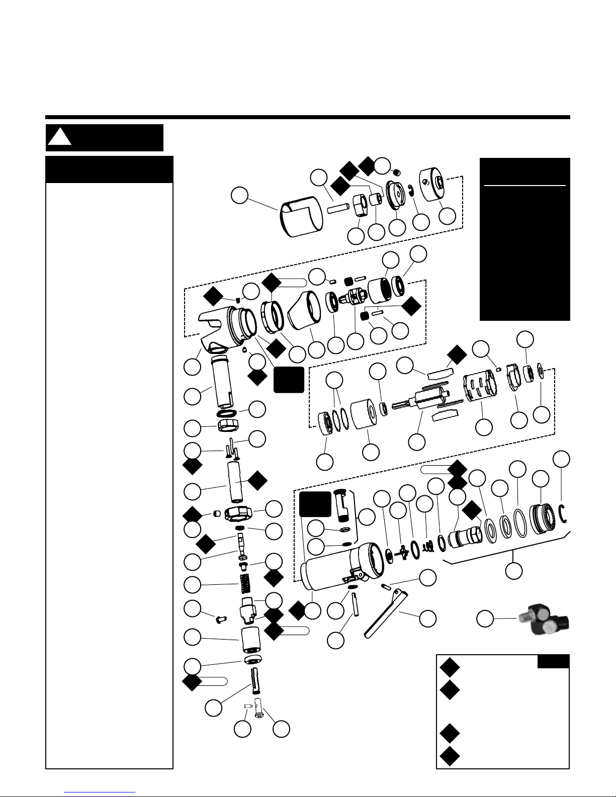
Motor Assembly/Disassembly Instructions – Dynadie®III
Important: Manufacturers warranty is void if tool is disassembled before warranty expires.
Notice: Dynabrade strongly recommends the use of their 52296 Repair Collar (sold separately) during assembly/disassembly activities. Failure to
use this collar will highly increase the risk of damage to the valve body of this tool. Please refer to parts breakdown for parts identification.
Motor Disassembly:
Important: Disconnect the Dynadie from the air supply before servicing any part of the tool.
1. Place the 52296 Repair Collar around the 12257 Housing and secure the tool in a vise so that the 02514 Housing is pointing up.
2. Use a 34mm or an adjustable wrench to remove the 01461 Lock Nut by turning it counterclockwise.
3. Pull the motor assembly out of the 12257 Housing.
4. Fasten the 96346 Bearing Separator around the portion of the 02506 Cylinder that is closest to the 02676 Rear Bearing Plate and place the motor assembly along with the
bearing separator on the table of the 96232 Arbor Press (#2) so that the rotor pinion is pointing toward the floor.
5. Remove the 02679 Shield from the 02696 Bearing.
6. Use a 3/16" dia. flat end drive punch as a press tool to press the 02504 Rotor out of the 02696 Bearing.
7. Remove the 02696 Bearing from the 02676 Rear Bearing Plate with the 96210 Bearing Removal Tool.
8. Use the bearing separator and the arbor press to remove the 02649 Bearing, the 02507 Front Bearing Plate, the 01479 Spacer and the 54529 Shims from the 02504 Rotor.
Motor Disassembly Complete.
Valve Disassembly:
1. Place the 52296 Repair Collar around the 12257 Housing and secure the tool in a vise so that the air inlet is pointing up.
2. Use two wrenches when removing the 94407 Flow Control Swivel and the air fitting. Place one wrench on the 01578 Inlet Adapter to hold it stationary and use another
wrench to remove the 94407 Flow Control Swivel and the air fitting.
3. Remove the inlet adapter from the 12257 Housing. Note: Refer to the exploded view of the muffler assembly to identify the parts and their correct order of assembly.
4. Use needle nose pliers to remove the 01468 Spring and the 01472 Tip Valve. The 01464 Seal can be removed from the 12257 Housing with a small screwdriver.
5. Use retaining ring pliers to remove the 95558 Retaining Ring and push the 01469 Speed Regulator Assembly along with the 01449 Valve Stem out of the housing.
6. Use a 2.5mm dia. drive punch to remove the 12132 Pin and the throttle lever.
Valve Disassembly Complete.
Work Head Assembly:
1. With the work head assembly removed from the motor housing secure the lower part of the 02514 Housing (The portion of the housing where the 01461 Lock Nut
attaches.) in a vise with aluminum or bronze jaws. Remove the 02581 Cover by pinching it between your thumb and index finger. Turn the cover counterclockwise until it
stops and then pull it off.
2. Use a hot air gun to apply heat to the 02586 Wrist Pin Coupler to soften the thread adhesive. Use the 96314 Open End Wrench (4mm) to unscrew the 02522 Ball Joint
from the 02586 Wrist Pin Coupler. Remove the slider assembly from the 02518 Barrel Slider.
3. Use the 95266 Hex Key (3mm) to loosen the 96071 Set Screw and remove the 02577 Barrel Control from the 02518 Barrel Slider.
4. Remove the 02586 Wrist Pin Coupler from the 02584 Dowel Pin.
5. Use the 95266 hex Key (3mm) to remove the 96071 Set Screw from the inside of the 02578 Yoke.
6. Remove the 02563 Crank.
7. Use a small screwdriver to remove the 02582 Retaining Ring from the inside of the 02578 Yoke.
8. Use the 96401 Hex Key (2mm) to remove the 50784 Set Screw from the 02514 Housing.
9. Place the 02514 Housing in the 96232 Arbor Press (#2) so that the 02510 Planetary Carrier is pointing down. Use a 3/16" dia. flat end drive punch as a press tool to
remove the planetary carrier.
10. Remove the 02579 Key from the planetary carrier.
11. Use the bearing separator and the arbor press to remove the 12153 Bearings (2) and the 02511 Ring Gear.
12. Note: Inspect the 02513 Gears (2) and the 02512 Gear Shafts (2) for fit and wear to determined if the gears and the shafts need to be replaced. If they are worn, remove
the shafts by placing the short stem of the 02510 Planetary Carrier in a vise with aluminum or bronze jaws so that the 02512 Gear Shafts can be driven out of the planetary
carrier. Use a 3/32" dia. drive punch to remove the shafts.
13. Use a hot air gun to apply heat and a 1/16" Hex Key to remove the 95291 Screws (2) from the 02514 Housing.
14. Secure the 02520 Slider in vise with aluminum or bronze jaws so that the 02573 Guard and the 02519 Tool Holder are pointing up. Use a hot air gun to apply heat to the
02574 Nut until it can be removed with a wrench by turning it in a counterclockwise direction. Use the 95252 Hex Key (2.5mm) to remove the 96113 Button Head Cap
Screw, and the 02573 Guard from the tool holder.
15. Once the 02520 Slider is cool enough to handle, remove the parts that are contained in the slider.
Work Head Disassembly Complete.
Work Head Assembly:
1. Place the 02520 Slider in vise with aluminum or bronze jaws so that the end with the internal thread is pointing up.
2. Install the 02521 Socket over the stem of the 02552 Ball Joint so that the chamfered side of the socket fits against the pivot end of the ball joint. Place these into the slider
so that the stem of the ball joint protrudes out through the opposite end of the slider.
3. Install the 02523 Retainer so that the flat side of the retainer is against the 02522 Ball Joint. Install the 02572 Spring into the slider and against the 02523 Retainer.
Apply a small amount of the 95848 Gear Oil into the slider to lubricate these parts.
4. Apply a small amount of the Loctite #567 (or equivalent) to the larger dia. threads of the 02519 Tool Holder and tighten the tool holder into the slider.
(Torque to 17 N•m/150 in.- lbs.)
5. Slip the 02573 Guard over the 02519 Tool Holder aligning the button screw hole with the threaded hole in the tool holder.
6. Use 95252 Hex Key (2.5mm) to install the 96113 Button Head Screw into the tool holder.
7. Apply a small amount of the Loctite #271 (or equivalent) to the threads of the tool holder and install the 02574 Nut. (Torque to 17 N•m/150 in.- lbs.)
8. Install the 02576 Scuff Plate and the 02575 Lock Plate onto the 02518 Barrel Slider. Apply a small amount of the Loctite #567 (or equivalent) to the threads of the
95291 Screw. Use a 1/16" hex key to attach all of these parts to the 02514 Housing with the 95291 Screws (2).
9. Place the longer stem of the 02510 Planetary Carrier in a vise with aluminum or bronze jaws so that the shorter stem is pointing up.
10. Apply a small amount of the 95848 Gear Oil to the 02513 Gears (2) and the 02512 Shafts (2).
11. Use a 1/4" dia. drive punch and a hammer to carefully install the gears and shafts into the 02510 Planetary Carrier.
12. Use the 96240 Bearing Press Tool and the 96232 Arbor Press (#2) to install the 12153 Bearing onto the longer stem of the planetary carrier. Note: Position the press
tool against the inner race of the bearing when pressing the bearing onto the stem of the planetary carrier.
13. Position and install the 02511 Ring Gear over the planetary gear assembly so that the ring gear fits onto the 12153 Bearing. Note: Orient the ring gear so that the set
screw hole will align with the set screw hole in the 02514 Housing once it is installed.
14. Apply a small amount of the Loctite #567 (or equivalent) to the threads of the 50784 Set Screw and install it into the 02514 Housing by using the 96401 Hex Key (2mm).
3