Spinner SmartLoad 25 kW User manual

SPINNER I Product Manual
Original instructions
SmartLoad 25 kW
BN 546404C0300
BN 546404C0301
products.spinner-group.com

Data subject to change without notice │ 10086002 │ Issue B│ 2023-09-28
www.spinner-group.com
2 / 26
SPINNER I Product Manual
Content
1Safety..................................................................................................................................................3
1.1 About this product documentation.....................................................................................................3
1.2 Intended use......................................................................................................................................3
1.3 Improper use .....................................................................................................................................3
1.4 Qualifications of personnel................................................................................................................3
1.5 Safety signs and symbols..................................................................................................................4
1.6 Signal words for hazard seriousness ................................................................................................4
1.7 Grouped safety messages for SPINNER broadcast products ..........................................................5
2Product identification...........................................................................................................................7
3Function...............................................................................................................................................7
3.1 General..............................................................................................................................................7
3.2 Coolant ..............................................................................................................................................7
3.3 Heat exchanger .................................................................................................................................8
3.4 Coolant circuit of the liquid cooling system .......................................................................................8
3.5 Interlock loop.....................................................................................................................................9
3.6 Operating and display elements......................................................................................................10
3.7 Maintenance cycle...........................................................................................................................10
4Storage..............................................................................................................................................10
5Transportation...................................................................................................................................11
6Installation.........................................................................................................................................12
6.1 Mechanical installation ....................................................................................................................12
6.2 Coolant level check and overflow hose installation.........................................................................14
6.3 Electrical installation........................................................................................................................14
7Commissioning and normal operation ..............................................................................................16
8Maintenance......................................................................................................................................17
8.1 PLC clock time setting.....................................................................................................................18
8.2 Deaeration of the cooling circuit......................................................................................................18
8.3 Checking glycol concentration.........................................................................................................20
8.4 Correcting the coolant level.............................................................................................................21
8.5 Coolant exchange............................................................................................................................22
9Warranty............................................................................................................................................23
10 Repairs..............................................................................................................................................24
11 Demounting.......................................................................................................................................24
12 Disposal.............................................................................................................................................25
13 Spare Parts .......................................................................................................................................26
14 Contacts............................................................................................................................................26

Data subject to change without notice │ 10086002 │ Issue B│ 2023-09-28
www.spinner-group.com
3 / 26
SPINNER I Product Manual
1 Safety
1.1 About this product documentation
The Spinner group makes every effort to keep the safety standard of our products up to date to be able to
offer our customers the highest possible degree of safety. Our products are designed and tested in
accordance with the relevant safety standards. There is, however, still a danger of personal injury or
damage to equipment if this chapter and the safety instructions in this documentation are not complied
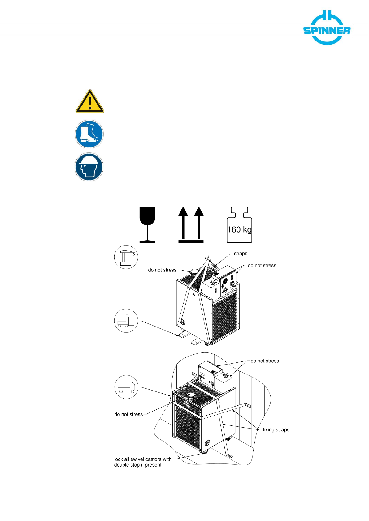
with. This documentation aims at persons commissioned with the transport, installation, commissioning,
operation, cleaning, maintenance, repairs, demounting and disposal of SPINNER SmartLoads. Read this
documentation completely and particularly the chapter "Safety", before working with the product. Keep this
product documentation available at the site and pass it on to the subsequent users. For all questions
regarding the safety you can contact SPINNER at any time.
1.2 Intended use
The intended use of the product is to terminate RF high power coaxial transmission lines. The SmartLoad
BN 546404C0300 and BN 546404C0301 is designed to absorb RF power of max. 25 kW in broadcast or
industrial indoor applications in operating rooms with restricted access. Access for authorized persons shall
be regulated by the operator.
Details and other limits are given in the attached data sheet 10086053.
The intended use of the product is assumed, if it is used in accordance with the requirements of the
applicable product documentation and within its performance limits (see appendices data sheet, circuit
diagram, material data sheet of the SPINNER coolant and the following safety instructions). Applicable
local or national safety regulations and rules for the prevention of accidents must be observed in all work
performed in conjunction with the product.
1.3 Improper use
The improper use of the product includes the use of the product:
•in operating rooms with unrestricted access
•in outdoor applications
•in explosion-prone atmosphere
•for transporting people or loads
•without correctly connected interlock system
•with covered inlet or exhaust air openings
•with modifications not authorized by SPINNER
•in damaged condition
•for private purposes
•in conditions and environments beyond the limits given in this product documentation
Any other use than described in the chapter intended use and in this product documentation is improper
use and therefore inadmissible.
1.4 Qualifications of personnel
Installation, commissioning, operation, maintenance, repairs and demounting of the product require
electrical and mechanical specialized knowledge. In order to ensure the safe use, these activities may
therefore only be carried out by qualified technical personnel or an instructed person under the direction
and supervision of qualified personnel. Qualified personnel are those who, due to professional training,
knowledge and experience as well as their understanding of the relevant regulations, are able to assess
the work assigned, to recognize possible hazards and to institute appropriate safety measures.
Qualified personnel must have appropriate safety equipment and must be trained in first aid.
The use of the product requires special training and a high level of concentration. It must be ensured that
persons who use the product are physically, mentally and emotionally able to comply with the
requirements, otherwise injuries or material damage may occur. The employer or operator must choose
suitable personnel for use of the product.

Data subject to change without notice │ 10086002 │ Issue B│ 2023-09-28
www.spinner-group.com
4 / 26
SPINNER I Product Manual
1.5 Safety signs and symbols
Safety signs are used on warning labels, stickers, in the product documentation and on the packaging of
the product.
Warning!
General hazard
Warning!
Danger of
electric shock
Warning!
Hot surface
PE terminal
Earth
Warning!
High weight
Warning!
Non-ionised
electromagnetic
radiation
No access for
persons with
pacemakers
Use safety shoes
Use safety helmet
Use safety gloves
Observe product
documentation
1.6 Signal words for hazard seriousness
Signal words are used on warning labels, stickers, in the product documentation, on specific danger spots
and on the packaging of the product. They indicate the hazard seriousness in safety messages.
DANGER Indicates a hazardous situation conveying great risk which, if not avoided, will result in death
or serious injury.
WARNING Indicates a hazardous situation conveying moderate risk which, if not avoided, could result in
death or serious injury.
CAUTION Indicates a hazardous situation conveying minor risk which, if not avoided, may result in
minor or moderate injury.
NOTICE Indicates the possibility of faulty operation that can damage the product.
It is essential to make sure that the signal words described here are always used only in connection with
the related product documentation and the related product. The use of signal words in connection with
unrelated products or documentation can result in misinterpretation and thus contribute to personal injury or
material damage.

Data subject to change without notice │ 10086002 │ Issue B│ 2023-09-28
www.spinner-group.com
5 / 26
SPINNER I Product Manual
1.7 Grouped safety messages for SPINNER broadcast products
Entire or multiple phases of product lifecycle
•Unless otherwise specified, these products are not protected against penetration of liquids, gases,
steam, etc. Failure to comply could result in electric shock or product damage, which could also lead to
serious injury.
•Blocking of constructive openings on the product (ventilation slots, fine leaks etc.) must be prevented,
because these are necessary for product operation. Failure to comply could lead to overheating and
could result in burns, fire and electric shock.
•Any object that is not designed to be placed in the openings of the housing must not be used for this
purpose. Doing so can cause short circuits inside the product and could result in electric shock, fire or
injury.
•Depending on the function, certain products such as RF radio equipment can produce an elevated level
of electromagnetic radiation. Considering that unborn babies require increased protection, pregnant
women must be protected by appropriate measures. Persons with pacemakers may also be exposed to
risks from electromagnetic radiation. The employer/operator must evaluate workplaces where there is a
special risk of exposure to radiation and, if necessary, take measures to avert the potential danger.
•As with all industrially manufactured goods, the use of substances that induce an allergic reaction
(allergens) such as nickel cannot be generally excluded. If you develop an allergic reaction (such as a
skin rash, frequent sneezing, red eyes or respiratory difficulties) when using a SPINNER product,
consult a physician immediately to determine the cause and to prevent health problems or stress.
•Should a fire occur, the product may release hazardous substances (gases, fluids, etc.) that can cause
health problems. Therefore, suitable measures must be taken, e.g. protective masks and protective
clothing must be worn.
Transport
•The product may be very heavy. In some cases, the user may require suitable lifting gear and means of
transportation to avoid back or other physical injuries.
•Transport the product only in the original packaging. Do not unpack until immediately prior to
installation. Failure to comply could result in death or serious injury.
Installation
•Do not place the product on heat-generating devices such as radiators or fan heaters. The ambient
temperature must not exceed the maximum temperature specified in the product documentation or in
the data sheet. Product overheating could result in burns, fire and electric shock.
•Do not place the product on surfaces, vehicles, cabinets or tables that for reasons of weight or stability
are unsuitable for this purpose. Always follow the installation instructions of the manufacturer when
installing the product and fastening it to objects or structures (e.g. walls and shelves). An installation
that is not carried out as described in the product documentation could result in death or serious injury.
•Mains driven products must be operated only from a TN power distribution system. The operator is
responsible for using an appropriate and sufficiently dimensioned AC power line. The AC power line
must be externally fused according to the product documentation. Failure to comply could result in fire
or electric shock.
•Operation of products with protection class I according to EN 61140 is permitted only with a mains cable
with protective earth connection. The protective conductor continuity must be inspected by an
electrically skilled person. Failure to comply could result in electric shock.

Data subject to change without notice │ 10086002 │ Issue B│ 2023-09-28
www.spinner-group.com
6 / 26
SPINNER I Product Manual
•All externally connected circuits for controlling, alerting and signalling have to be fed from ES1 type
sources acc. to IEC 62368-1 only. The current in these circuits has to be externally limited by means of
fuses to values indicated in the product documentation. Failure to comply could result in fire and electric
shock.
•Dangerous voltage must not reach the product over the outer conductor/waveguide. Failure to comply
could result in electric shock.
•If the product is equipped with a ground terminal connection (equipotential connection), the ground
terminal must be connected sufficiently dimensioned to earth. Failure to comply could result in electric
shock.
Commissioning / Operation
•Products in operation may be hot. Touching them could result in burns.
•Before applying RF-power to the product, ensure proper connection and matching (load, line, etc.) of all
RF-connectors. Ensure sufficient mechanical rigidity of the RF-connections. Failure to comply could
result in serious injuries by non-ionised electromagnetic radiation.
•Operation of the product with a damaged cable is not permitted. All cables must be checked on a
regular basis to ensure that they are in proper operating condition. By taking appropriate safety
measures and carefully laying the power cable, ensure that the cable cannot be damaged and that no
one can be hurt or suffer an electric shock by e.g. tripping over the cable.
•Front panels, lids and covers must not be removed during operation. Otherwise, live components can
be accessible. This could result in electric shock, fire and serious injury.
•If the product is subjected to pressure, the locally and nationally applicable guidelines for pressure
vessels must be applied. Failure to comply could result in death or serious injury.
Cleaning
•Prior to cleaning, turn off all feeding transmitters and disconnect them from the power supply. Use a
soft, lint-free, dry cloth for cleaning. Do not use chemical cleaners. Perform cleaning only after cooling-
down. Failure to comply could result in electric shock and burns.
Repair
•Troubleshooting and repairs should only be carried out by qualified technical personnel or an instructed
person under the direction and supervision of qualified personnel (see chapter 1.4 " Qualifications of
personnel"). Observe the section safety messages and in particular chapter 1 "Safety" of this product
manual. Failure to comply could result in death or serious injury.
•Do not modify the product and use only spare parts tested and approved by SPINNER. Failure to
comply could result in death or serious injury.
Disposal
•The operator is responsible for disposing of the product according to national waste disposal
regulations. Improper disassembly or disposal may be hazardous.
•If hazardous substances or operation materials are used for operation of the product, which must be
periodically disposed of (e.g. coolant), these materials must be treated in accordance with the safety
instructions of the hazardous substance or operating material manufacturer and the national waste
disposal regulations. Also observe the relevant safety instructions in this product documentation. Failure
to comply could result in serious injury and environmental damage.

Data subject to change without notice │ 10086002 │ Issue B│ 2023-09-28
www.spinner-group.com
7 / 26
SPINNER I Product Manual
2 Product identification
The SPINNER SmartLoads BN 546404C0300 or BN 546404C0301 have a type plate containing the
following information for product identification:
3 Function
3.1 General
The resistor element of the SmartLoad, consisting of a cylindrical ceramic substrate coated with
special resistive material, absorbs the RF power and converts it into heat. An unpressurized liquid
cooling system with coolant pump and closed cooling circuit is used for transferring the heat from the
resistor element, via a heat exchanger with forced air cooling, to the surrounding area.
3.2 Coolant
The coolant ANTIFROGEN N is a well-balanced yellow coloured mixture of distilled water, ethylene
glycol and a rust preventative. The composition ensures excellent protection against corrosion and
freezing. The coolant supplied is a mixture of distilled water, 39% by volume ethylene glycol and a
corrosion inhibitor.
Observe the attached material data sheet of the coolant when filling up, emptying or
deaerating the cooling system or disposing of the coolant. For an updated copy of the
material data sheet refer to the link or QR code below:
https://products.spinner-group.com/AntifrogenN

Data subject to change without notice │ 10086002 │ Issue B│ 2023-09-28
www.spinner-group.com
8 / 26
SPINNER I Product Manual
3.3 Heat exchanger
A radiator fan is used for re-cooling of the heat sink.
NOTICE Ensure unobstructed air circulation to avoid overheating.
3.4 Coolant circuit of the liquid cooling system
A pressureless closed cooling circuit with radiator fan is used for heat release. The coolant is pumped
through the resistor element W and the heat exchanger K by means of the coolant pump P. The
expanse vessel AB is added due to the thermal expansion of the coolant. The outer surface
temperature of the resistor element and the coolant temperature are monitored by means of the
temperature controllers B1 and B2. Leakage from the resistor element is monitored by the float switch
B3.

Data subject to change without notice │ 10086002 │ Issue B│ 2023-09-28
www.spinner-group.com
9 / 26
SPINNER I Product Manual
3.5 Interlock loop
The internal interlock loop for protection of the SmartLoad consists of a programmable logic controller
(PLC), temperature controllers, float switch and signal contacts. The logic of the PLC combines all
six sensory inputs like switches connected in series to control the interlock loop, which is closed
during normal operation of the SmartLoad. Any open switch shuts down all transmitters connected
to the interlock loop.
•The temperature controller B1 opens at resistor temperatures above 260 °C. After opening the
interlock at 260 °C the load element needs to cool down to 60 °C before the interlock is closed
again. The overtemperature threshold will be reduced gradually to 190 °C and 120 °C to keep
the load element temperatures in a safe range.
Between the interlock open temperature of 120°C and the interlock close temperature of 60°C
unlimited operation is possible.
After 6 hours of trouble-free operation or a power cycle the interlock open threshold will be reset
to 260 °C.
•The temperature controller B2 opens at coolant temperatures above 90 °C and closes below
80 °C.
•The float switch B3 opens when it detects coolant leaks.
•The protection function of the frequency inverter VFD1 for the coolant pump motor M1 opens at
coolant pump motor overload.
•The protection function of the frequency inverter VFD2 for the ventilator motor M2 opens at
ventilator motor overload.
•The main switch interlock is open in power off position of the main switch.
WARNING
Electric shock hazard
Electric shock can cause severe burns and fatal injuries.
Do not use the interlock loop for personal protection
Schematic diagram of the switching status during normal operation:
The internal interlock loop complies with the requirements for Electrical energy Source class 1 (ES1
type according to IEC 62368-1, safe separation, proof voltage resistance 4 kV ACpk to primary
circuit).
The maximum permissible voltage for the interlock loop and to the grounded housing is 42.4 V ACpk
respectively 60 V DC. The power supply must be fully compliant with the ES1 type requirements.
The circuit has to be limited externally to 1 A.

Data subject to change without notice │ 10086002 │ Issue B│ 2023-09-28
www.spinner-group.com
10 / 26
SPINNER I Product Manual
3.6 Operating and display elements
Green indicator light “READY“:
Some 10 seconds after main switch turned on, the green light indicates readiness for operation:
•Mains voltage is connected
•Main switch is turned on
•No fault occurred
Red indicator light “WARNING”:
The red light indicates that the interlock loop of the SmartLoad is interrupted. All transmitters
connected properly to the interlock loop are turned off.
The red indicator lamp lights, if the mains voltage is connected and the main switch is turned on
and at least one of the following five conditions is true:
•Resistor element temperature too high
•Coolant temperature too high
•Float switch triggered
•Motor protection VFD1 triggered
•Motor protection VFD2 triggered
Front panel fan
The fan mounted on the front panel of the control cabinet is required for cooling of the frequency
inverters VFD1 and VFD2. The fan runs if the pump is operating at full speed.
3.7 Maintenance cycle
To ensure proper longterm operation of the coolant pump, the PLC activates autonomous
maintenance cycles daily for the duration of a few minutes, refer to “PLC clock time setting” in the
attached PLC manual 10058594.
4 Storage
Keep dry and avoid exposure to sudden temperature changes to prevent condensation.
Environmental conditions for storage are specified in the attached data sheet 10086053.
Do not unpack until immediately prior to installation.
NOTICE Do not remove any connector protection cap until immediately prior to installation
to avoid formation of dust and scratches on sensitive RF contact surfaces.
Environmental conditions for storage refer to attached data sheet TD-00060

Data subject to change without notice │ 10086002 │ Issue B│ 2023-09-28
www.spinner-group.com
11 / 26
SPINNER I Product Manual
5 Transportation
CAUTION
Crushing Hazard
The SmartLoad is heavy. Crushing or falling may cause injuries.
Use suitable lifting gear approved to carry at least 160 kg.
Do not stand below the SmartLoad.
To ensure stability, keep the product in the supplied transport packaging until
immediately prior to installation.
Do not lift the SmartLoad at the RF connector.
Do not stress the expanse vessel and the control cabinet.
Safety shoes and hardhat are required.
NOTICE Environmental conditions for transportation refer to attached data sheet TD-00060

Data subject to change without notice │ 10086002 │ Issue B│ 2023-09-28
www.spinner-group.com
12 / 26
SPINNER I Product Manual
6 Installation
Before you start, ensure to read and understand the section safety messages and in
particular chapter 1 "Safety" of this product manual. Only electrically skilled persons
should install SPINNER SmartLoads in accordance with the national safety and
accident prevention regulations.
Failure to observe could result in death or serious injury.
6.1 Mechanical installation
WARNING
Crushing Hazard
Falling objects may cause death and serious injury.
The SmartLoad is heavy. Use suitable lifting gear only. The lifting gear must be
approved to carry at least 160 kg.
Do not lift the SmartLoad at the RF connector.
Do not stress the expanse vessel and the control cabinet.
Use suitable fasteners if mounted in an elevated position.
Safety shoes are required. If it is necessary to stand below the SmartLoad during
installation, safety shoes and hardhat are required.
WARNING
Electric shock hazard
Electric shock can cause severe burns and fatal injuries.
Do not install and operate the SmartLoad in environmental conditions beyond the
specifications given in the attached data sheet 10086053. The SmartLoad is
designed for indoor application on operating sites with limited access only
Floor Installation

Data subject to change without notice │ 10086002 │ Issue B│ 2023-09-28
www.spinner-group.com
13 / 26
SPINNER I Product Manual
The SmartLoad must be installed on a flat and solid ground with bearing capacity higher than
160 kg to ensure stability. The front panel, main switch and filling port need to be easily accessible.
Do not install the SmartLoad on escape routes, corridors or close to temperature sensitive
equipment. Required floor space for best possible cooling capacity is specified in the installation
drawing below. Slight unevenness of the floor can be compensated by means of the levelling feet.
The SmartLoad can be additionally fixed with the lower M6 mounting threads. The M6 threads near
to the RF connector can be used for mounting a traverse to support the RF cable.
NOTICE Ensure unobstructed air circulation to avoid overheating.
Do not reduce the ground clearance if installed without levelling feet.
Ceiling installation:
The SmartLoad must be installed on a solid ceiling with bearing capacity higher than 500 kg to
ensure stability. The front panel, main switch and filling port need to be easily accessible. Do not
install the SmartLoad close to temperature sensitive equipment. Ensure sufficient pass line heights
and the required cooling air flow space, refer to floor installation.
NOTICE Ensure unobstructed air circulation to avoid overheating.
Threaded rod through the housing: M10 or 3/8”
Tensile strength min. 400 N/mm²
Yield point min. 240 N/mm²
Recommended tightening torque for counter nut: 30 Nm

Data subject to change without notice │ 10086002 │ Issue B│ 2023-09-28
www.spinner-group.com
14 / 26
SPINNER I Product Manual
6.2 Coolant level check and overflow hose installation
SPINNER supplies the SmartLoad with correct coolant level and deaerated cooling circuit.
The SmartLoad is equipped with a level indicator. The marking indicates the minimum and the
maximum permissible level of the coolant.
NOTICE The coolant level may exceed the marked maximum at temperatures
above 25 °C.
Check the coolant level prior to commissioning.
Prevent dry running of the coolant pump.
Follow the instructions given in chapter 8.4 if correction of the
coolant level is required.
Connect the supplied hose (1) to the cap (2). Place a suitable collecting container (4) with a
capacity of at least 10 l next to the SmartLoad and insert the hose (1) into the collecting container
(4). In the event of a malfunction with a sudden rise in pressure in the cooling circuit, escaping
coolant is drained via the hose into the collecting container.
The expansion tank has a membrane for continuous adaptation to the ambient pressure.
6.3 Electrical installation
WARNING
Electric shock hazard
Electric shock can cause severe burns and fatal injuries.
Before you start ensure to disconnect your entire system from the power supply.
Utilize appropriate devices and methods to prevent accidental energizing.
WARNING
High leakage current
Connect at least 10 mm² PE conductor permanently to separate PE terminal before
connecting mains connector.
WARNING
Radio Frequency Hazard
Radio Frequency Power can cause burns, eye injuries and electrical shock.
Before connecting the RF cable, ensure to disconnect your entire system from the
power supply. Utilize appropriate devices and methods to prevent accidental
energizing.
NOTICE
To avoid overheating caused by RF overload ensure to connect all relevant
transmitters to the interlock system of the SmartLoad prior to commissioning.

Data subject to change without notice │ 10086002 │ Issue B│ 2023-09-28
www.spinner-group.com
15 / 26
SPINNER I Product Manual
•Connect a PE conductor of at least 10 mm² with cable lug permanently to marked separate
PE terminal, either at the top of the switch cabinet (M8 screw) or at the bottom on the rear of
the frame (M8 screw), before connecting any other wire.
•Connect the interlock loop:
Option 1
Mount the supplied interlock loop connector on a suitable cable and attach the connector to
the two-pole screw locking IEC 60130-9 port on the rear side of the control box.
Option 2
Alternatively use the cable gland on the rear side of the control box to run the interlock cable
to the terminals inside the control box in accordance with the attached circuit diagram
10085127 for BN 546404C0300 resp. 10085151 for BN 546404C0301. Push a screwdriver
into the rectangular opening of the clamp, insert the wire into the round opening and then
pull out the screwdriver.

Data subject to change without notice │ 10086002 │ Issue B│ 2023-09-28
www.spinner-group.com
16 / 26
SPINNER I Product Manual
Check proper function of the interlock system prior to commissioning. Do not use the
interlock loop for personal protection.
The maximum permissible voltage for the interlock loop and to the grounded housing is
42.4 V ACpk respectively 60 V DC. The power supply must be fully compliant with the ES1
type requirements according to IEC 62368-1. The circuit has to be limited externally to 1 A.
•Mount a suitable mains connector to the supplied IEC 60320-1 C19 socket power cord
according to the attached circuit diagram.
Mains connector requirements:
BN 546404C0300 230 V AC, 50 Hz to 60 Hz, 10 A, 3x2.5 mm²
BN 546404C0301 115 V AC, 50 Hz to 60 Hz, 16 A, 3x2.5 mm²
Alternatively, a standard mains cable with a cross-section of 3x2.5 mm² and an IEC 60320-1
C19 socket can be used.
Use an easily accessible socket located close to the SmartLoad for mains connection.
Connect the SmartLoad only to TN networks (L, N, PE):
BN 546404C0300 230 V AC, 50 Hz to 60 Hz
BN 546404C0301 115 V AC, 50 Hz to 60 Hz
•Connect RF using connectors according to IEC 339 only.
•Relieve all connections to the SmartLoad from any bending torque, e.g. caused by heavy
cables or assemblies.
•Check sufficiently dimensioned PE-connection and PE-continuity prior to commissioning.
•Check functioning of the interlock loop by turning the main switch (S1) into the off position.
7 Commissioning and normal operation
Before you start, ensure to read and understand the section safety messages
and in particular chapter 1 "Safety" of this product manual. Only electrically
skilled persons may commission and operate SPINNER SmartLoads in
accordance with the national safety and accident prevention regulations.
Failure to observe could result in death or serious injury.
For latest maintenance procedures and updates, please check our website https://www.spinner-
group.com/en/products/smart-load-service regularly at least every six months and register your
product there.
Before applying RF power to the SmartLoad electrically skilled persons have to ensure:
•proper connection of all system connectors
•proper functioning of the interlock loop, all relevant transmitters must be connected to the
interlock system of the SmartLoad.
•unobstructed air circulation; do not cover the ventilation openings.
•the SmartLoad is switched on, the green indicator lights.
After each actuation of the main switch the device runs a maintenance cycle. During this cycle the
red indicator lights and the interlock loop is open. No RF power can be absorbed.

Data subject to change without notice │ 10086002 │ Issue B│ 2023-09-28
www.spinner-group.com
17 / 26
SPINNER I Product Manual
Open the switch cabinet and set, if applicable, the clock time and date as described in the attached
PLC manual 10058594.
During operation, the pump and fan switch on as needed. This depends on the RF power applied
and the ambient temperature.
8 Maintenance
Before you start, ensure to read and understand the section safety messages and in
particular chapter 1 "Safety" of this product manual. Only trained persons may
clean SPINNER SmartLoads in accordance with the national safety and accident
prevention regulations.
Failure to observe could result in death or serious injury.
WARNING
Electric shock hazard
Electric shock can cause severe burns and fatal injuries.
Before you start ensure to disconnect your entire system from the power supply.
Utilize appropriate devices and methods to prevent accidental energizing.
Do not use any liquids for cleaning.
WARNING
Entanglement Hazard
The ventilators may entangle hair, clothing or jewelry causing death or serious
injury.
Wait until all rotating parts have stopped.
Wear a hair net and close-fitting clothing.
CAUTION
Hot surface
The resistor element heats up during normal operation and may cause burns.
Do not remove any covers.
Do not touch the resistor element before cooled down
Detailed maintenance descriptions and videos are available at:
https://www.spinner-group.com/en/products/smart-load-service
Maintenance schedule:
Weekly:
•Verify correct coolant level and ensure that there are no leaks present.
•Ensure that there are no black particles and / or burned smell.
•Press pump button on back of electrical cabinet for a few seconds to activate pump for
check. Check again for leakage.

Data subject to change without notice │ 10086002 │ Issue B│ 2023-09-28
www.spinner-group.com
18 / 26
SPINNER I Product Manual
Monthly:
•Verify the unobstructed air circulation of the heat exchanger. Remove dust or dirt from the
heat exchanger with compressed air or a soft brush.
Quarterly:
•Verify installed software is the most current revision, refer to https://www.spinner-
group.com/en/products/smart-load-service
Annually:
•Perform functional test on all reject SmartLoads. See video "Functional Test" for detailed
instructions, refer to https://www.spinner-group.com/en/products/smart-load-service
•Check if the filter on fan of electrical cabinet is saturated with dusk. If so, it can be vacuum
cleaned or shook out and used again. In dusty environments, we recommend cleaning the
filter regularly to avoid decreasing fan performance.
•Check glycol concentration, refer to chapter 8.3.
Every 4 years:
•Exchange coolant, refer to chapter 8.5.
8.1 PLC clock time setting
Before you start, ensure to read and understand the section safety messages
and in particular chapter 1 "Safety" of this product manual. Only electrically
skilled persons may open the control box of SPINNER SmartLoads and set the
PLC clock time in accordance with the national safety and accident prevention
regulations.
Failure to observe could result in death or serious injury.
Details are given in the attached PLC manual 10058594.
8.2 Deaeration of the cooling circuit
Before you start, ensure to read and understand the section safety messages and in
particular chapter 1 "Safety" of this product manual. Observe the material data sheet
of the coolant. Only qualified personnel may deaerate SPINNER SmartLoads in
accordance with the national safety and accident prevention regulations.
Failure to observe could result in death or serious injury.
WARNING
Electric shock hazard
Electric shock can cause severe burns and fatal injuries.
Before you start ensure to disconnect your entire system from the power supply.
Utilize appropriate devices and methods to prevent accidental energizing.
WARNING
Radio Frequency Hazard
Radio Frequency Power can cause burns, eye injuries and electrical shock.
Before you start ensure to disconnect your entire system from the power supply.
Utilize appropriate devices and methods to prevent accidental energizing.

Data subject to change without notice │ 10086002 │ Issue B│ 2023-09-28
www.spinner-group.com
19 / 26
SPINNER I Product Manual
CAUTION
Hot surface
The resistor element heats up during normal operation and may cause burns.
Do not remove any covers shortly after use of the SmartLoad.
Do not touch the resistor element before cooled down.
CAUTION
Poisoning Hazard
Skin or eye contact may cause irritation. Inhaling may irritate the respiratory organs.
Avoid skin or eye contact. Do not inhale gases, fumes and aerosols.
Observe the attached safety data sheet M36457 of the coolant.
Wear safety gloves
Wear eye protection
1. Check coolant level and refill coolant if required, refer to chapter 8.4.
2. Deaeration of the cooling circuit:
•Wait until no more air bubbles appear in the expansion tank.
•Connect interlock and mains cables.
•Turn on the main switch.
NOTICE Pump must not run dry.
•Push the pump button for 2 min, then stop and wait until no more bubbles come up in the
reservoir. Repeat this procedure a few times until no more bubbles show up.
NOTICE Faultless functioning of the SmartLoad can only be guaranteed, if the cooling system
is deaerated properly. The coolant has to be clear and free of any bubbles.

Data subject to change without notice │ 10086002 │ Issue B│ 2023-09-28
www.spinner-group.com
20 / 26
SPINNER I Product Manual
8.3 Checking glycol concentration
Before you start, ensure to read and understand the section safety messages
and in particular chapter 1 "Safety" of this product manual. Observe the material
data sheet of the coolant. Only qualified personnel may check the glycol
concentration of SPINNER SmartLoads in accordance with the national safety
and accident prevention regulations.
Failure to observe could result in death or serious injury.
WARNING
Electric shock hazard
Electric shock can cause severe burns and fatal injuries.
Before you start ensure to disconnect your entire system from the power supply.
Utilize appropriate devices and methods to prevent accidental energizing.
WARNING
Radio Frequency Hazard
Radio Frequency Power can cause burns, eye injuries and electrical shock.
Before you start ensure to disconnect your entire system from the power supply.
Utilize appropriate devices and methods to prevent accidental energizing.
CAUTION
Poisoning Hazard
Skin or eye contact may cause irritation. Inhaling may irritate the respiratory organs.
Avoid skin or eye contact. Do not inhale gases, fumes and aerosols.
Observe the attached safety data sheet M36457 of the coolant.
Wear safety gloves
Wear eye protection
Unscrew the cap of the coolant filling port.
•Measure glycol concentration with usual antifreeze testing device for ethylene glycol.
The optimum glycol concentration is 39 % (equals antifreeze up to -24 °C).
Below 34 % glycol concentration (equals antifreeze up to -19 °C) Coolant needs to be
replenished. Drain off excess coolant at the reservoir.
Above 44 % glycol concentration (equals antifreeze up to -29 °C) thin down coolant with
distilled water. Drain off excess coolant at the reservoir.
Screw on cap of filling port.
Other manuals for SmartLoad 25 kW
1
This manual suits for next models
2
Table of contents
Other Spinner Test Equipment manuals

Spinner
Spinner BN 533855 User manual

Spinner
Spinner BN 533831 User manual

Spinner
Spinner BN 533810 User manual

Spinner
Spinner BN 533842 User manual

Spinner
Spinner NEX10 BN 355112 User manual

Spinner
Spinner SmartLoad 50 kW User manual

Spinner
Spinner BN 225312 User manual

Spinner
Spinner BN 533420 User manual

Spinner
Spinner BN 533840 User manual