Spinner BN 533842 User manual

OSLT Calibration Kit
2.4 mm (50 ohms)
BN 533842

Data subject to change without notice │ M36002│Issue D│2020-02-21
www.spinner-group.com
2 / 11
Dear Customer,
Thank you for the trust you have placed in us by buying a SPINNER calibration kit. Each SPINNER calibration kit
is carefully tested and subject to strict quality controls by Spinner’s quality assurance. Nevertheless, the service
life of a calibration kit depends to a great extent on you. Observe the information contained in these instructions
and the enclosed documentation. The more carefully you treat your calibration kit, the longer it will provide
dependable service.
Certification
Spinner GmbH certifies that this product met its published specifications at the time of shipment from the factory.
Spinner GmbH further certifies that all measurements are traceable to national or international standards and to
natural physical constants or mathematical models.

Data subject to change without notice │ M36002│Issue D│2020-02-21
www.spinner-group.com
3 / 11
Content
1.General Safety Information ......................................................................................................................... 4
2.Product Identification .................................................................................................................................. 6
3.Intended Use ............................................................................................................................................... 6
4.Improper Use .............................................................................................................................................. 6
5.Scope of Delivery ........................................................................................................................................ 6
5.1 Offset Opens and Shorts ............................................................................................................................ 7
5.2Broadband Loads........................................................................................................................................ 7
5.3Adapters ...................................................................................................................................................... 7
6.Calibration Data .......................................................................................................................................... 7
7.Identification of Component Serial Numbers .............................................................................................. 7
8.Data Sheet .................................................................................................................................................. 7
9.Use and Preventive Maintenance ............................................................................................................... 7
9.1 Cleaning Connectors .................................................................................................................................. 8
9.2Gauging Connectors ................................................................................................................................... 9
9.3 Connection and Disconnection ................................................................................................................... 9
10.Handling and Storage ............................................................................................................................... 10
11.Recalibration ............................................................................................................................................. 10
12.Spare parts ............................................................................................................................................... 10
13.Disposal .................................................................................................................................................... 11
14.Warranty ................................................................................................................................................... 11
15.Contacts .................................................................................................................................................... 11
Data subject to change without notice │ M36002│Issue D│2020-02-21
www.spinner-group.com
4 / 11
1. General Safety Information
The following instructions and safety instructions are to be carefully read and followed!
The Spinner group makes every effort to keep the safety standard of our products up to date to be able to
offer our customers the highest possible degree of safety. Our products are designed and tested in
accordance with the relevant safety standards. Compliance with these standards is continuously monitored
by our quality assurance system. The product described here has been designed and tested in accordance
with the respective EU guidelines and has left the manufacturer’s plant in a condition fully complying with
safety standards. To maintain this condition and to ensure safe operation, observe all instructions and
warnings provided. If you have any questions regarding these safety instructions, the Spinner group will be
happy to answer them.
The operator is responsible for using the product in an appropriate manner. This product must not be used in
any way that may cause personal injury or property damage. The operator is responsible if the product is
used for an intention other than its designated purpose or in disregard of the manufacturer's instructions. The
manufacturer shall assume no responsibility for such use of the product.
The product is used for its designated purpose if it is used according to the specifications listed in the
product’s documentation within its performance limits (see data sheet, performance specifications, circuit
diagram, the following safety instructions).
Putting the product into operation requires special technical skills and must be executed by qualified
personnel with reference to “Start up information” in the product documentation Keep the basic safety
instructions and the product documentation in a safe place and pass them on to the subsequent users.
Symbols and safety markings
Observe basic
safety instructions
-
Observe product
documentation
Danger of
electric shock Warning! Non
ionised
electro magnetic
radiation
Ground
Observing the safety instructions will help prevent personal injury or damage of any kind caused by
dangerous situations. Therefore, carefully read through and adhere to the following safety instructions before
putting the product into operation. It is also absolutely essential to observe the additional safety instructions
on personal safety that appear in relevant parts of the product documentation.
Tags and their meaning
DANGER Indicates a hazardous situation conveying great risk which, if not avoided, will result in death
or serious injury.
WARNING Indicates a hazardous situation conveying moderate risk which, if not avoided, could result in
death or serious injury.
CAUTION Indicates a hazardous situation conveying minor risk which, if not avoided, may result in minor
or moderate injury.
ATTENTION Indicates the possibility of faulty operation that can damage the product.
These tags are in accordance with the standard definition for civil applications in the European Economic
Area. Definitions that deviate from the standard definition may also exist in other economic areas or military
applications. It is therefore essential to make sure that the tags described here are always used only in
connection with the related product documentation and the related product. The use of tags in connection
with unrelated products or documentation can result in misinterpretation and thus contribute to personal
injury or material damage.

Data subject to change without notice │ M36002│Issue D│2020-02-21
www.spinner-group.com
5 / 11
Basic Safety Instructions
1. These products must be operated only under the operating conditions specified in this product
documentation. Observe all instructions for start up, operation and servicing listed in the product
documentation.
2. Applicable local or national safety regulations and rules for the prevention of accidents must be
observed in all work performed and only by authorized specially trained personnel.
3. Dangerous voltage must not reach the outer conductor / waveguide of the product.
4. Before applying RF-power to the product, ensure proper connection and matching (load, line, etc.) of
all RF-connectors. Ensure sufficient mechanical rigidity of the RF-Connections. If the product is
equipped with an interlock loop, it must be connected to the transmitter’s interlock system and tested
for function
5. Unless expressly permitted, never remove the cover or any part of the housing while the product is in
operation. Doing so will expose circuits and components and can lead to injuries, fire or damage to
the product.
6. Repair must be carried out only by the manufacturer or technical personnel authorized by the
manufacturer.
7. Unless otherwise specified, Spinner products are not protected against penetration of liquids, gases,
steam, etc. If this is not taken into account, there exists the danger of electric shock for the user or
damage to the product, which can also lead to personal injury.
8. Spinner products are not explosion-proof. They must not be operated in explosion-prone areas.
9. Never use the product under conditions in which condensation has formed or can form in or on the
product, unless otherwise specified.
10. Please be aware that in the event of a fire, toxic substances (gases, liquids etc.) that may be
hazardous to your health may escape from the product.
11. Do not place the product on heat-generating devices such as radiators or fan heaters. The
temperature of the environment must not exceed the maximum temperature specified in the data
sheet.
12. Improper use of the product can produce an elevated level of electromagnetic radiation. The
employer/operator is required to assess workplaces where there is a special risk of exposure to
radiation and, if necessary, take measures to avert the danger.
13. The operator is responsible for disposing of the product according to national waste disposal
regulations. Improper disassembly or disposal may be hazardous.
14. Use suitable overvoltage protection to ensure that no overvoltage (such as that caused by a
thunderstorm) can reach the product. Otherwise the operating personnel will be endangered by
electric shocks.
Data subject to change without notice │ M36002│Issue D│2020-02-21
www.spinner-group.com
6 / 11
2. Product Identification
The SPINNER calibration kit BN 533842 has a type label on the top of the box containing the
following information for product identification:
OSLT- Calibration Kit 2.4 mm (50 Ohms)
BN 533842 (SPINNER part number)
Ser. No: XXX (Serial number)
3. Intended Use
The intended use of the calibration kit BN 533842 is to calibrate vector network analyzers (VNAs) up
to 50 GHz for measurements of components with 2.4 mm connectors.
Details and other limits are given in the data sheet file “533842-BE.pdf” on the USB stick.
The product may only be operated within the specifications given in the
data sheet file “533842-BE.pdf” on the USB stick. Failure to observe
could result in death or serious injury.
4. Improper Use
The product is not intended for any other purpose than indicated above.
If the calibration kit is not used as intended, safe operation of this product cannot be guaranteed. The
user is responsible for all personal injury and property damage resulting from improper use. Reading
the manual as well as adhering to all the information provided – particularly the safety instructions -
is considered mandatory to comply with the intended use.
5. Scope of Delivery
The calibration kit BN 533842 includes the following items:
Offset open plug
Offset open socket
Offset short plug
Offset short socket
Broadband load plug
Broadband load socket
2.4 mm adapter plug-plug
2.4 mm adapter socket-socket
Torque wrench size 8 mm, 90 Ncm
Certificate of Calibration incl. calibration data
USB stick containing files of following documents:
- This product manual “M36002.pdf”
- Certificate of calibration “Certificate of calibration.pdf”
- Individual calibration data and serial numbers of the calibration kit components
“Calibration Data.pdf”
- Product data sheet “533842-BE.pdf”
- Handling instructions for torque wrench BN 154141R000 “M31071.pdf”
A complete listing of the calibration kit content incl. the SPINNER part numbers is provided in the
spare part section of this manual.
ATTENTION A backup copy of all files on the USB-Stick should be made available for data
safety reasons.

Data subject to change without notice │ M36002│Issue D│2020-02-21
www.spinner-group.com
7 / 11
5.1 Offset Opens and Shorts
The piece parts of the offset opens and shorts are produced with state-of-the-art precision
machinery. The mechanical design of the opens and shorts provides very small mechanical pin and
socket gauges, resulting in minimum phase errors. The opens and shorts are designed to have a
phase offset of approx. 180° at all frequencies.
5.2 Broadband Loads
The broadband precision loads are 50 Ω terminations that have been optimized for best performance
up to 50 GHz. The high-strength internal structure provides very repeatable connections. A tempered
resistor element on high quality ceramics provides excellent stability and return loss.
5.3 Adapters
Like the other devices in the kit, the adapters are produced with extremely tight tolerances to provide
good broadband performance and ensure stable, repeatable connections.
To allow use in calibration procedures for non-insertable devices, all adapters feature the same
nominal electrical lengths.
6. Calibration Data
The calibration data in formats for several common VNAs can be found in the file "Calibration
Data.pdf" on the USB-Stick. The matching calibration data has to be entered manually into the
network analyzer. Check the manual of the network analyzer for instructions.
ATTENTION The calibration data is individually belonging to each component of the kit. Using
the individual calibration data for other components may result in reduced
measurement accuracy.
7. Identification of Component Serial Numbers
In addition to the serial number of the kit, the components of the kit have individual serial numbers
too. These serial numbers are listed in the file "Calibration Data.pdf" on the USB stick. The serial
numbers prevent to mistake components of this kit with similar components of other kits.
8. Data Sheet
The electrical, mechanical and environmental specifications of the calibration kit are given in the data
sheet file “533842-BE.pdf” on the USB stick. The data sheet is also available for download at
www.spinner-group.com.
ATTENTION Temperature changes may have an impact on electrical characteristics. Therefore,
the operating temperature is a critical performance factor. During a calibration
sequence, the temperature of the calibration components must be stable and
within the specified operating temperature range. Avoid unnecessary touching of
components during the calibration sequence; your fingers apply heat to them.
ATTENTION The pin depth of each calibration component in the kit is specified in data sheet file
“533842-BE.pdf” on the USB stick. If the pin depth of a component is not measured
within the pin depth limits, extended by the measurement uncertainty, the
component may not meet electrical specifications.
9. Use and Preventive Maintenance
The best measures for maintaining the accuracy of the components in the kit include:
routine visual inspection
cleaning
Data subject to change without notice │ M36002│Issue D│2020-02-21
www.spinner-group.com
8 / 11
proper gauging
proper connecting techniques
Failure to detect and remove dirt or metallic particles on a mating plane surface can degrade
repeatability and accuracy and can damage any connector mated to it. Improper connections,
resulting from improper pin depth values, or from bad connection techniques, can also damage these
devices. For the pin depth limits refer to the data sheet file “533842-BE.pdf” on the USB stick.
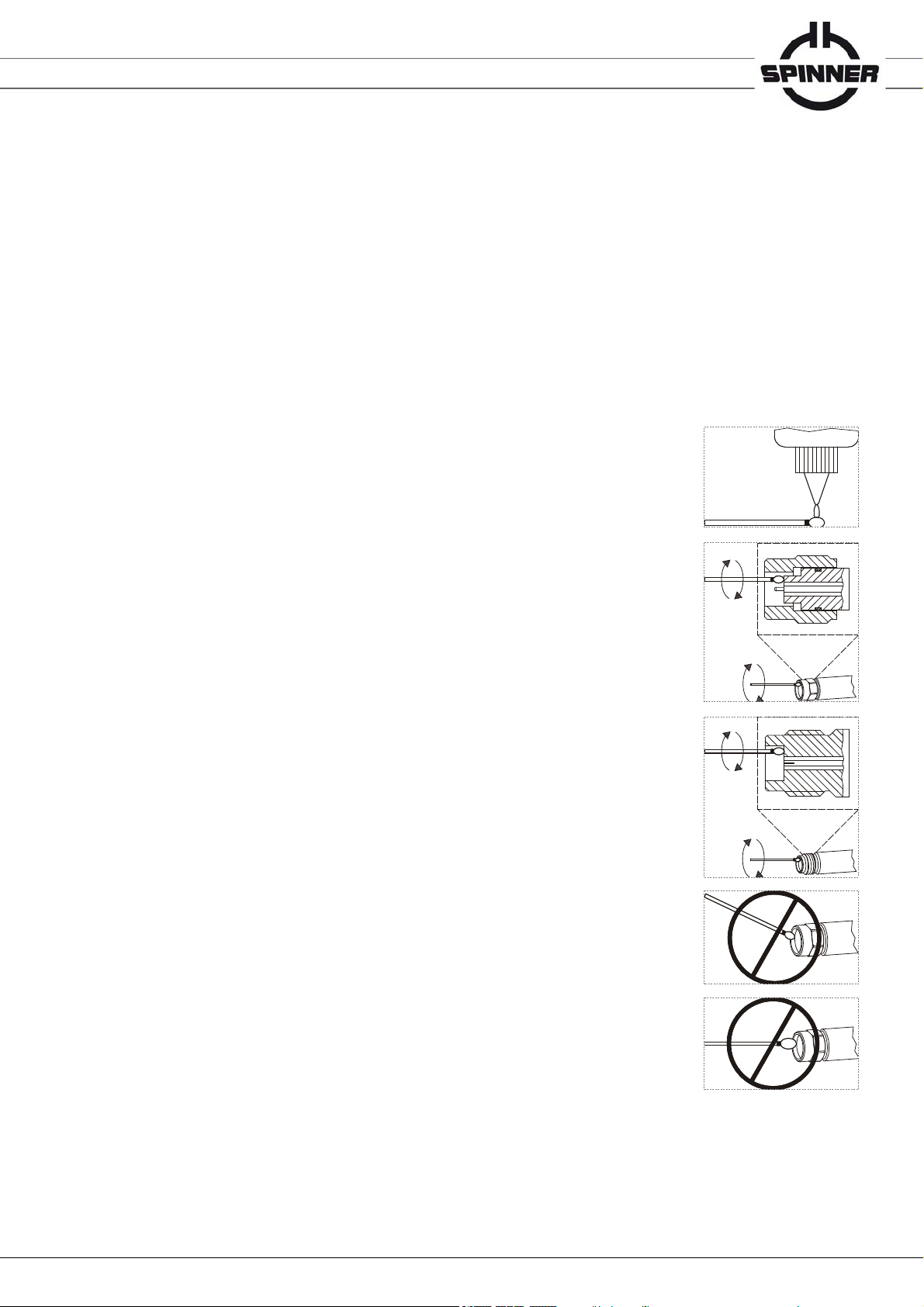
9.1 Cleaning Connectors
A sufficient cleaning of the connectors is essential to ensure the integrity of the RF connections. Dial
gauge and connector interfaces, especially the outer conductor, should be kept clean and free of dirt and
other debris.
- Dampen a lint-free swab with denaturised alcohol.
- Gently rotate the swab in the interface around the inner conductor being
careful not to stress or bend the pin.
- Ensure that no foreign material remains in the interface after cleaning.
- Ensure that the inner conductor of the connector has not been bent
or damaged.
ATTENTION
• Only dampen the swab. Do NOT saturate it.
• Do NOT use other cleaning fluids or solvents than denaturised alcohol.
Do NOT use water.
• Do NOT put in the swab at an angle; otherwise you will damage
the connector.
• Do NOT use too large swabs; otherwise you will damage the connector.
Only use lint-free swabs which are designed for precision applications
needing pinpoint accuracy (e.g. swabs with polyvinylidene fluoride tip).
• Never put lateral pressure on the connector’s inner conductor.
• The inner conductor does not require cleaning.

Data subject to change without notice │ M36002│Issue D│2020-02-21
www.spinner-group.com
9 / 11
9.2 Gauging Connectors
Connector gauges are used to evaluate the pin depth of connectors. The accuracy of commercially
available gauges is not sufficient to precisely measure the connector pin depth of the kit
components.
Sufficient measurement accuracy for preventive maintenance and troubleshooting can be achieved
as follows:
Use SPINNER gauge (refer to spare part list in chapter 12
Temperature of the gauge and the kit component has to be within 23°C ± 5°C
Apply coupling torque 90 Ncm with the torque wrench of the kit considering the handling
instructions given in the file “M31071.pdf” on the USB stick
The permissible pin depth test results, considering a measurement uncertainty of a measurement
done with a new SPINNER gauge and the mentioned conditions, are shown in data sheet file
“533842-BE.pdf” on the USB stick.
9.3 Connection and Disconnection
This chapter describes the process of achieving proper connections.
Connection
Ground yourself and all components to prevent electrostatic discharge from the
measurement assembly.
Perform visual inspection of the connectors.
Clean the connectors sufficiently.
Use a proper dial gauge to ensure that all inner conductors are within the pin depth limits
extended by the measurement uncertainty, specified in the data sheet file “533842-BE.pdf”
on the USB stick (refer also to the above chapter “Gauging Connectors” ).
Align the connectors carefully. The plug inner conductor has to intrude concentrically into the
bushing of the socket connector.
Push the connectors straight together and tighten the coupling nut hand-tight until the mating
plane surfaces have contact.
Do not turn the component body. Only turn the coupling nut.
Do not overstrain the connection.
ATTENTION Damage to the inner conductor may occur, if the component body is turned.
Support the connectors properly. Relieve the connections from any bending torque, caused
for example from heavy assemblies or cables.
For the final connection use the supplied torque wrench. The torque wrench is unalterable
set to the required torque 90 Ncm ± 10 %. Refer to the handling instructions of the torque
wrench (M31071.pdf) for proper handling.
Disconnection
Support the connectors properly to relieve the connections from any bending torques and
forces.
Do not turn the component body. Only turn the coupling nut.
ATTENTION Damage to the inner conductor may occur, if the component body is turned.
Prevent the component body from turning.
Unfasten the coupling nut with an open-end wrench.
Separate the components in turning only the coupling nut. Disconnect the components
straight without any bending, twisting or rocking of the connectors.

Data subject to change without notice │ M36002│Issue D│2020-02-21
www.spinner-group.com
10 / 11
10. Handling and Storage
ATTENTION The calibration kit components are sensitive to impact. Do not drop!
Keep dry and avoid exposure to sudden temperature changes to prevent condensation.
Environmental conditions for storage are specified in the data sheet file “533842-BE.pdf” on the USB
stick.
Put the calibration components into the plastic tubes, close the tubes with the protective
caps and store them in the foam inlays of the box when not in use.
Never store components loose without the protection of plastic tube and box. This is the
most common cause of damages during storage.
Avoid touching mating plane surfaces with your fingers. Residues on the connector interface
may degrade the performance of the components and can only be removed with difficulty.
Always make sure that the connectors are in a clean condition.
Avoid the contact of the components interface surfaces with any hard material. The plating
and the mating plane surfaces may be damaged if the interface contacts any hard surface
uncontrolled.
After any shock to a component (e.g. drop down on the floor) recalibration is recommended.
11. Recalibration
The suggested initial interval for recalibration is 12 months or 500 matings, whichever comes first.
The actual need for recalibration depends on the use and the maintenance of the kit. The
recalibration interval should begin with the day of initial use after recalibration.
The SPINNER recalibration service includes
cleaning of the connector interfaces
gauging of the pin depth of each component to verify the compliance with the specification
electrical testing of each component
a new calibration sticker affixed to the case
a calibration certificate
12. Spare parts
Components included in the calibration kit BN 533842:
Ordering Number Component Quantity per kit
BN 533774R000
BN 533775R000
BN 533772R000
BN 533773R000
BN 533770R000
BN 533771R000
BN 533777R000
BN 533776R000
BN 154141R000
Open plug
Open socket
Short plug
Short socket
Load plug
Load socket
Through plug-plug
Through socket-socket
Torque Wrench 8 mm / 90 Ncm
1
1
1
1
1
1
1
1
1

Data subject to change without notice │ M36002│Issue D│2020-02-21
www.spinner-group.com
11 / 11
Components not included in the calibration kit BN 533842, offering additional options:
Ordering Number Component
BN 537078
BN 537079
BN 533778R000
BN 741650R000
BN 741651R000
Dial gauge plug (includes reference gauge)
Dial gauge socket (includes reference gauge)
Through plug-socket
Sliding load plug
Sliding load socket
13. Disposal
WARNING Improper disassembly or disposal may be hazardous.
Some parts are made of cross linked polystyrene and copper beryllium. The user is responsible for
disposing of the calibration kit in accordance with the national waste disposal regulations.
14. Warranty
Do not disassemble any component of the calibration kit. The warranty is void, if components are
modified, improperly handled or third party intervention or modification has occurred.
15. Contacts
SPINNER GmbH • Headquarters
Erzgiessereistr. 33
80335 München
Germany
tel.: +49 89 12601-0
fax: +49 89 12601-1292
www.spinner-group.com
SPINNER Telecommunication
Devices Co., Ltd.
351 Lian Yang Road
Songjiang Industrial Zone
Shanghai
201613 P.R. China
tel.: +86 21 577 45377
fax: +86 21 577 40962
Table of contents
Other Spinner Test Equipment manuals

Spinner
Spinner BN 533840 User manual

Spinner
Spinner NEX10 BN 355112 User manual

Spinner
Spinner BN 533831 User manual

Spinner
Spinner BN 533810 User manual

Spinner
Spinner SmartLoad 25 kW User manual

Spinner
Spinner SmartLoad 50 kW User manual

Spinner
Spinner BN 533855 User manual

Spinner
Spinner BN 225312 User manual

Spinner
Spinner BN 533420 User manual


