Spinning SPINNER BLADE User manual

OWNER’S MANUAL
SPINNER®BLADE
SPINNER®BLADE ION

www.spinning.com 800.847.SPIN (7746)
SPINNER®BLADE AND
SPINNER® BLADE ION
The Spinner®Blade and Spinner®Blade ION feature the same design
geometry, heavy-duty construction and aluminum style adjustments from
our commercial series bikes in package that is perfect for home use.
As the creators of Spinning®and the worldwide leaders in indoor cycling
bikes and programs, we’re here to help you get the most out of every ride.
Whether your goal is to lose a few pounds, stay in shape or train for the
next race, the team at Spinning®is here to help you every step of the way.
This owner’s manual is just the beginning.
The Spinner®Blade and Spinner®Blade Ion oer the same heavy-duty
construction as our commercial Spinner®bikes in a package that is perfect
for home use.
If you purchased the Spinner Blade, you can upgrade it later with our
Performance SPINPower crank. The Blade ION is equipped with the
Performance SPINPower crank and you will be ready to train with power.
Need help? Scan the code to check out our Spinning®Support Video
Library and other useful information about your new bike and the
Spinning®program.
Enjoy the ride.

SPINNER® BLADE AND SPINNER® BLADE ION OWNER’S MANUAL
www.spinning.com 800.847.SPIN (7746)
3
© 2017 Mad Dogg Athletics, Inc. All rights reserved.
CONTENTS
11 Welcome to the Spinning® Program
12 Spinning® Program Safety
14 Your Spinner® Bike
15 Caring for Your Spinner® Bike
16 Bike Assembly
20 Testing the Bike
21 Troubleshooting
22 Pedal Adjustments
22 Brake Pad Replacement
23 Warranty

© 2021 Mad Dogg Athletics, Inc. All rights reserved.
4
IMPORTANT SAFETY PRECAUTIONS
This bike has been designed and constructed for a safe and comfortable ride.
Nevertheless, certain precautions should be taken when using any piece of
exercise equipment. Read the whole manual before assembling and using the
bike. The following safety precautions should also be observed:
1. Keep children and pets away from the Spinner®bike at all times.
Parents and/or those responsible for children should always take their
curious nature into account and the potential of induced hazardous
situations and behavior resulting in accidents. Under no circumstances
should this Spinner®bike be used as a toy.
2. The owner is responsible for ensuring that anyone who uses the
machine is duly informed about the necessary outlined precautions
and proper way to ride.
3. This bike can only be used by one person at a time.
4. Use suitable clothing and footwear. Make sure all laces/cords are tied
and tucked-in so that they are not loose or can be tangled into any
parts of the bike.
5. Turn the resistance knob clockwise until the flywheel is locked when
the bike is not in use.
!
• FAILURE TO READ AND FOLLOW THE INSTRUCTIONS IN THIS MANUAL MAY RESULT IN
POSSIBLE SERIOUS INJURY.
• PEDAL SPEED SHOULD BE REDUCED IN A CONTROLLED MANNER.
• FIX YOUR FOOT IN THE PEDAL CAGE OR SPD CLEAT DURING EXERCISING TO
PREOVENT UNINTENTED MOVING.
• IT’S IMPORTANT TO ADJUST AND SECURE THE HANDLEBAR AND SEAT TO YOUR
DESIRED POSTION FOR A COMFORTABLE AND SAFE RIDE. DO NOT EXCEED MINIMUM
INSERTION DEPTH MARKS LABELED ‘STOP’ OR ‘MAX’ ON THE HEAD POST AND SEAT
POST VERTICAL ADJUSTMENTS.
WARNING
THANK YOU!
Thank you for purchasing your new Spinner®Blade bike. Your bike has been
designed and engineered for safety, durability and to provide a great ride. The
following pages will outline a number of safety precautions and part diagrams
for your reference. It is important to thoroughly read through this manual and
follow all warnings for the best overall experience with your new ride.

SPINNER® BLADE AND SPINNER® BLADE ION OWNER’S MANUAL
www.spinning.com 800.847.SPIN (7746)
5
6. This bike does not free-wheel. Pedals will continue to spin. Use caution
when slowing and stopping. In an emergency, stop pedaling and push
the resistnace knob down as an emergency brake to stop the pedals and
flywheel from rotating. Uncontrolled spinning pedals can cause injury.
7. If you experience dizziness, nausea, chest pains or any other
symptom while using this bike STOP exercising and SEEK MEDICAL
ATTENTION IMMEDIATELY.
8. Install and ride the bike on a mat that is placed on a level, solid surface
and that has a minimum of 1 meter (39.4”) of unobstructed space around
it on all sides. Adjust the stabilizer feet to make the bike level, secure and
stable on all four feet at the same time.
9. Keep hands well away from any of the moving parts.
10. Wear clothing suitable for riding. Do not wear loose or baggy clothing that
might get caught up in the parts of the bike. Always wear cycling shoes or
athletic shoes with laces tucked in when using the bike.
11. This bike must only be used for the purposes described in this manual.
DO NOT use accessories that are not recommended by Spinning®.
12. Dierently abled people should not use the bike without the assistance
of a qualified person or a doctor. This is not a medical device and
should be used with caution.
13. Do not use the bike if it is not working correctly.
14. Review all warning labels axed to the bike and replace any label
that is damaged, illegible, or removed. Contact customer service at
Spinning.com for replacements.
15. Functional and visual inspections of the bike should be made before
the bike assembly is complete and prior to any ride.
16. Do not exceed the MAX/STOP mark when adjusting the handlebar
post or seat post.
17. Spinning®pedals can cause injury. Pedal speed should be reduced in a
controlled manner.
18. Before using the bike, thoroughly inspect the bike for proper assembly.
19. User must adjust the seat and handlebars to suit the user’s dimensional
requirements. When adjusting, please insure that the bike is stable
and that the resistance knob is turned to clockwise to immobilize the
flywheel. Thoroughly tighen the corresponding adjustment knobs to
insure that the seat and handlebars are secure before riding.
20. This bike should only be used for home (consumer) use and is not
meant for commercial use.
© 2021 Mad Dogg Athletics, Inc. All rights reserved.
6
21. Before every ride please examine brake pad, pedals and drivetrain for
signs of wear. The brake pad is a normal wear item and may need to
be replaced over time.
22. This bike is not suitable for therapeutic use and is for consumer use
only. Consult a physician prior to starting any exercise program.
23. The safety level of the bike can be maintained only if it is examined
regularly for damage and wear (e.g. brake pad, saddle, pedals,
drivetrain, etc).
24. Replace defective or worn components immediately and/or refrain
from using the bike until it is serviced or repaired.
25. Special attention must be paid to all wear components (e.g. brake pads, etc.).
26. Please adjust the handlebar and seat to your best biomechanical
positioning. Incorrect form and/or excessive training may result in injury.
27. Turn the resistance knob counter-clockwise to release the brake
before exercising.
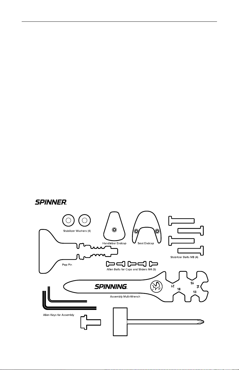
TOOLS INCLUDED FOR SPINNER®BIKE ASSEMBLY
Use the included tools for bike assembly only.
Blade/Blade ION
14mm Crank Bolt 14mm Socket Wrench for Crank Assembly
(Tools and Hardware)
BIKE INFORMATION AND SPECIFICATIONS
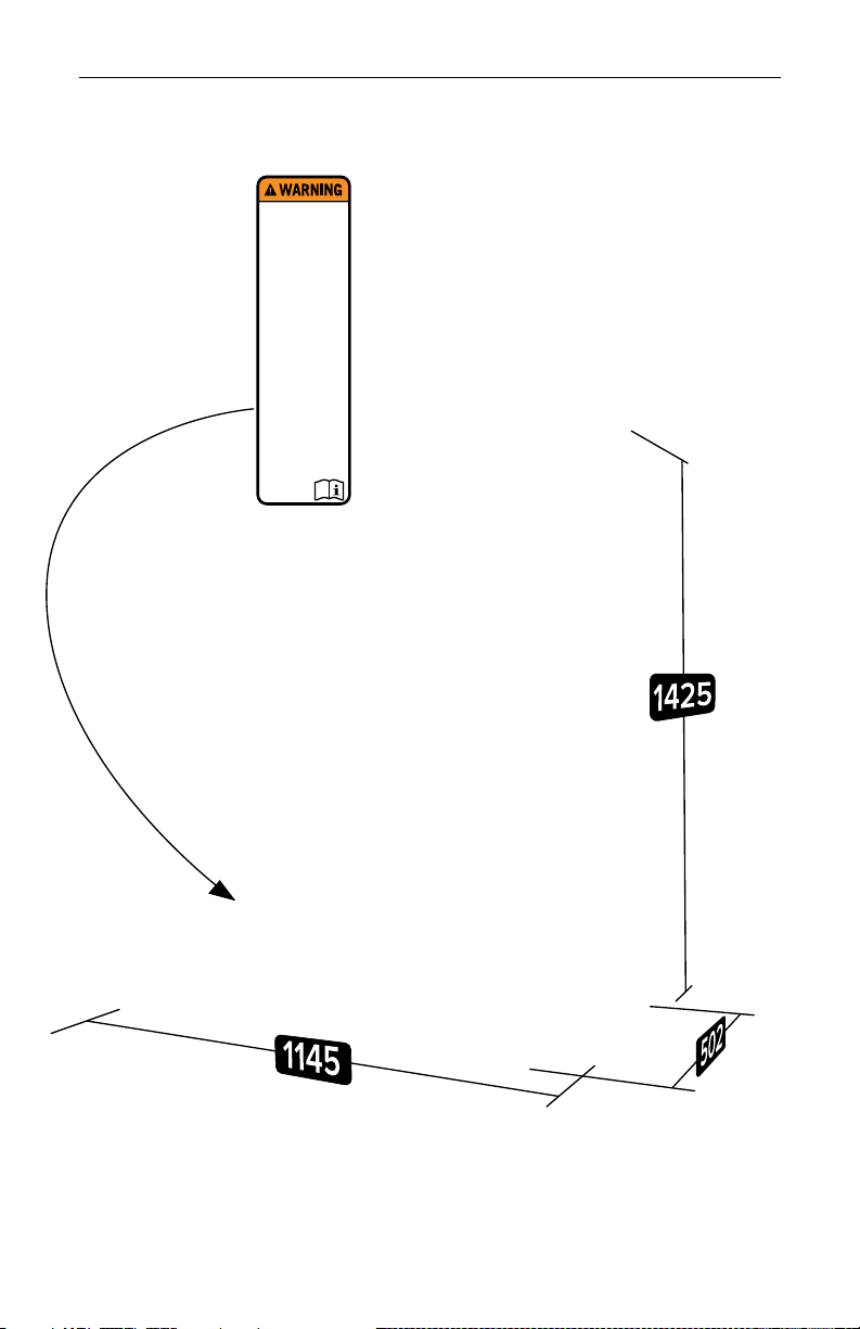
SPINNER BLADE AND BLADE ION- 123.5 Lbs (56 Kg)
ASSEMBLED SIZE: 1145mm Long x 502mm Wide x 1425mm Tall (avg, without tablet installed)
WARNING LABEL LOCATION
Read and properly follow all
warnings and instructions prior
to using the bike. Improper use,
misuse and uncontrolled pedals
can result in serious injury.
1. As with all exercise equipment or
programs, consult a physician prior
to use and stop if you feel faint, dizzy
or exhausted.
2. Keep children and pets away from
the bike at all times.
3. Install the bike with a minumum of
39” (1m) of unubstructed space on all
sides and on a level surface.
4. Always ride in control. To stop,
reduce your pedal speed in a
controlled way.
5. To stop quickly, push down on the
resistance knob to activate the brake.
6. This bike does not free-wheel.
Pedals will continue to spin. Use
caution when slowing and stopping.
7. Keep body parts and clothing free
and clear of all moving parts.
10. Maximum user capacity is limited
to 350 lbs. (159.1 kgs).
13. This product is not intended for
theraputic or commercial use.
15. Replace this label if damaged,
illegible or removed.
12. Lock the equipment and set the
resistance to maximum when the
bike is not in use.
14. The exercise bicycle should only
be used after a thorough reviw of the
operation manual (consumer
exercise bicycles).
11. Spinning pedals can cause injury.
8. Ensure that all adjustments and
locking features are properly secured
before using the bike.
9. Inspect the bike prior to riding and
replace worn, loose or damaged
parts prior to use.
SPINNER® BLADE AND SPINNER® BLADE ION OWNER’S MANUAL
www.spinning.com 800.847.SPIN (7746)
7
BIKE INFORMATION AND SPECIFICATIONS
SPINNER®BLADE AND SPINNER®BLADE ION - 123.5 Lbs (56 Kg)
BIKE INFORMATION AND SPECIFICATIONS
SPINNER BLADE AND BLADE ION- 123.5 Lbs (56 Kg)
ASSEMBLED SIZE: 1145mm Long x 502mm Wide x 1425mm Tall (avg, without tablet installed)
WARNING LABEL LOCATION
Read and properly follow all
warnings and instructions prior
to using the bike. Improper use,
misuse and uncontrolled pedals
can result in serious injury.
1. As with all exercise equipment or
programs, consult a physician prior
to use and stop if you feel faint, dizzy
or exhausted.
2. Keep children and pets away from
the bike at all times.
3. Install the bike with a minumum of
39” (1m) of unubstructed space on all
sides and on a level surface.
4. Always ride in control. To stop,
reduce your pedal speed in a
controlled way.
5. To stop quickly, push down on the
resistance knob to activate the brake.
6. This bike does not free-wheel.
Pedals will continue to spin. Use
caution when slowing and stopping.
7. Keep body parts and clothing free
and clear of all moving parts.
10. Maximum user capacity is limited
to 350 lbs. (159.1 kgs).
13. This product is not intended for
theraputic or commercial use.
15. Replace this label if damaged,
illegible or removed.
12. Lock the equipment and set the
resistance to maximum when the
bike is not in use.
14. The exercise bicycle should only
be used after a thorough reviw of the
operation manual (consumer
exercise bicycles).
11. Spinning pedals can cause injury.
8. Ensure that all adjustments and
locking features are properly secured
before using the bike.
9. Inspect the bike prior to riding and
replace worn, loose or damaged
parts prior to use.
© 2021 Mad Dogg Athletics, Inc. All rights reserved.
8
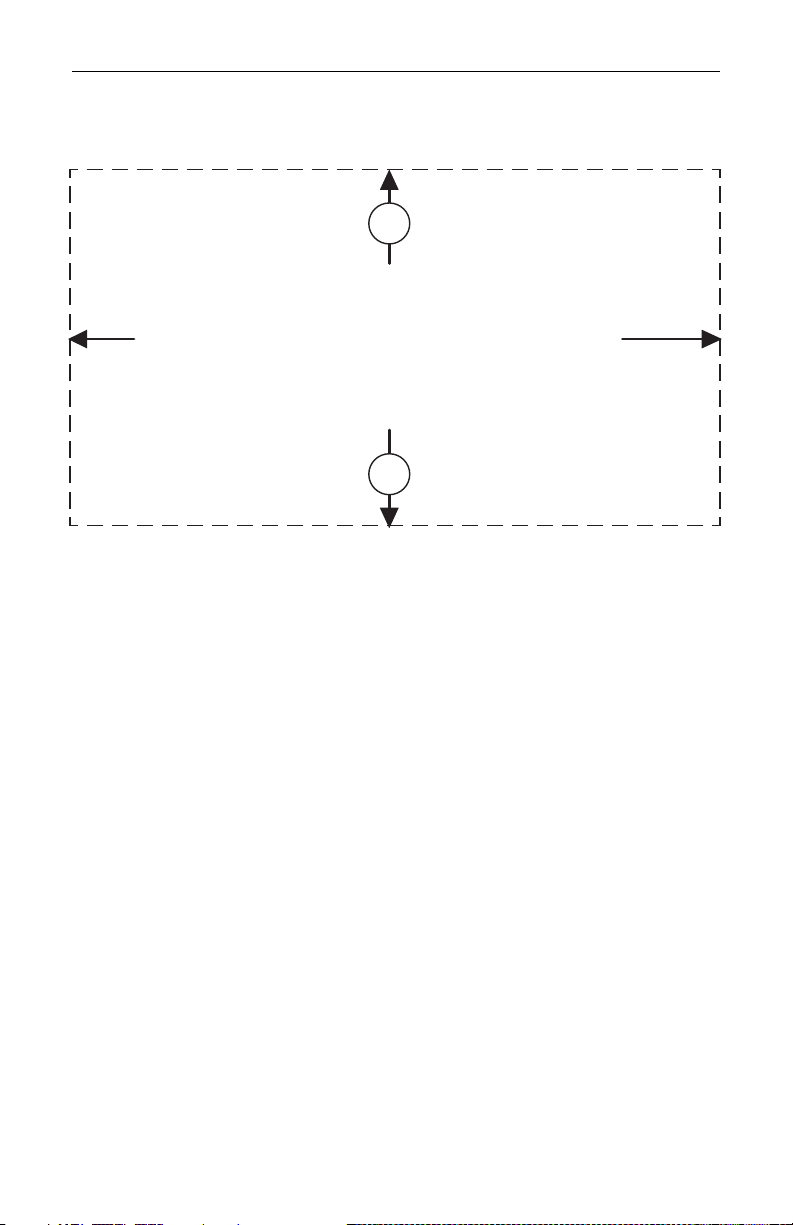
PERIMETER SPACE:
Keep at least 1 meter (39.4”) of clear space around the entire bike
OPERATION AND INSTALLATION PERIMETER
OPERATION AND INSTALLATION PERIMETER
PERIMETER SPACE: Keep at least 1 meter (39.4”) of clear space around the entire bike
39.4”
1m

SPINNER® BLADE AND SPINNER® BLADE ION OWNER’S MANUAL
www.spinning.com 800.847.SPIN (7746)
9
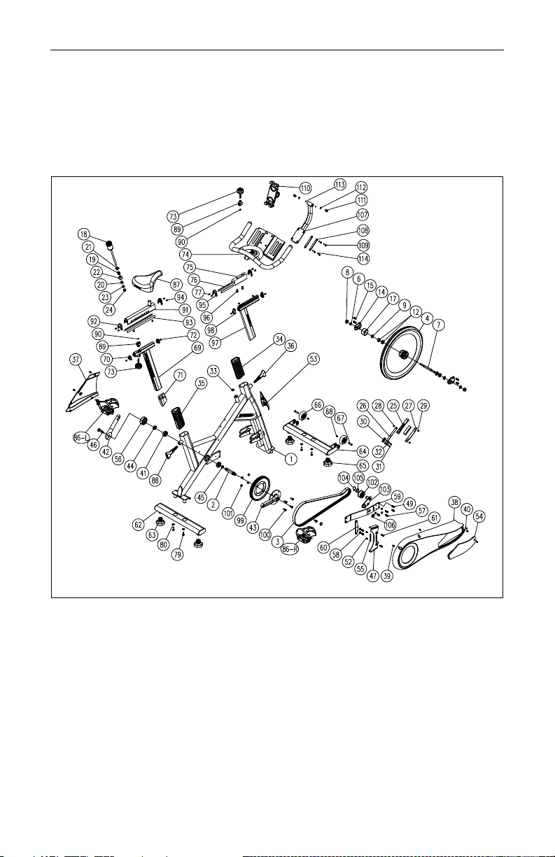
SPINNER® BLADE AND BLADE ION PARTS LIST
Part No.
Description Specifications Part No. Description Specifications
1 frame 1 62 rear stabilizer 1
2 axle φ20*109L 163 adjusting cap (PA+) M30*3.0 2
4flywheel
φ460*35W(18kg) 164 front stabilizer 1
6flat washer φ12.5*φ24*2.5t 265 adjusting cap (PA+) M30*3.0 2
7flywheel axle φ15*164L 166 transporation wheel ∮76*15W PU 90A 2
8nut M12 2 67 screw φ8*M6*35L 2
9bushing φ25*φ12.1*7.5L 268 screw M6x10L(5m/m) 2
12 bearings (2 per side) 6001RS 469 aluminum seat post 1
14 flywheel locator bracket 270 slider cover (ABS)2
15 hexagonal nut M8x12L 471 seat post end cap 1
17 flywheel cap PVC 1 72 screw M4x8L 2
18 braking knob M10*271L 173 knob (ABS)1
19 spring φ18.3*2.4*22.4L 174 front handlebar 1
20 bushing for braking
Ф10*Ф18*16L 175 front handlebar upper slider 1
21 spring holder (upper)
20*20*12L 176
internal handlebar slider glide
(PE)2
22 spring holder (lower) 20*20*21 M10 177 screw M4x8L 8
23 hexagonal nut M10(8t)178 wrench tool 13.14.15.18.21 (LOGO)1
24 nut M10 1 79 screw M8xP1.25x25L 4
25 brake pad holder aluminum 180 flat washer φ8xφ19x1t 4
26 brake spring 2t 181 washer M5x20L(3m/m) 1
27 brake pad 143.5*20*4.5T 184 hexagonal wrench 3mm 24mmL x 74mmL 1
28 hexagonal screw M6x10L(5m/m) 1 85 hexagonal wrench 6mm 30mmL x 84mmL 1
29 hexagonal screw
M5x6L 1 86 pedal JD-037V 9/16" 1
30 brake holder (PP)187 saddle SP-14 1
31 hexagonal screw M5x15L 288 T-knob M20xP2.5*63L (POM+PA) 1
32 flat washer φ5.5xφ10x1t 289 nut 27.8*36*21.8 Q235 1
33 brake sleeve (PP)190 nut M5 1
34 handlebar sleeve (PA) 191 seat slider 1
35 seat post sleeve (PA) 192 slider cap (ABS)1
36 pop pin
M20xP2.5*63L (POM+PA)
193 internal seat slider glide (ABS)2
37 inner cover (ABS ) 194 screw M4x8L 3
38 chainguard (ABS ) 195 handlebar slider upper cover (ABS)2
39 screw M5x16L 30# 596 screw M8x16L 5 2
40 screw M5x12L 30# 497 handlebar post 1
41 bearing 6004RS 298 handlebar slider lower cap (ABS)2
42 left crank (9/16") 22mm 199 large pulley φ204.7*6 1
43 right crank (9/16") 22mm 1100 hexagonal screw M8xP1.25x20L 6.8 4
44 nylon nut M20*P1.0 1101 nylon nut M8 4
45 flat washer φ20xφ25x2t 3102 idler wheel φ50x25mmL PA 1
46 nylok screw M8xP1.0x20L(30#) 8.8 2103 idler
PW7329+PW7330+PW7331+PW7332
1
47 finger guard (rear) (ABS ) 1104 C-type ring φ20 65Mn 1
49 screw M5xP0.8x12L 8.8 4105 curved washer φ20xφ30x0.3t 65Mn 1
52 screw M4x14L 2106 nylon nut M20*P1.0 1
53 front cover (ABS ) 2PCS PB7774 1107 tablet support bracket 1
54 garage door (ABS ) 1108 fixed plate 2T 2
55 plastic cover holder (ABS) 1109 screw M6x12L(5m/m) 4
56 shaft cap (PVC) 1110 tablet holder 4.7-12.9 ADV-306 1
57 screw M8x16L 8111 screw M8x20L 2
58 flat washer φ8xφ16x2t 4112 spring washer
φ8.4*φ18*1.5T 2
59 connector 5t 1113 flat washer
φ8 2
60 finger guard holder PW7324 + PW7325 1114 flat washer φ8 2
61 hexagonal screw M5x20L(3m/m) 2
© 2021 Mad Dogg Athletics, Inc. All rights reserved.
10
SPINNER®BLADE AND SPINNER®BLADE ION
EXPLODED VIEW

SPINNER® BLADE AND SPINNER® BLADE ION OWNER’S MANUAL
www.spinning.com 800.847.SPIN (7746)
11
WELCOME TO THE SPINNING®PROGRAM
Spinning® was born on the road, raised in the studio, and made for your
home. We’ve helped millions of people around the world get into the best
shape of their lives and we can’t wait to ride with you.
The bike is just the beginning! Now you can create your own Spinning®
experience by choosing content and gear for a ride tailored just for
you. Try one of our apps on for size with a free trial for the Spinning®
subscription of your choice.
Spinning® Digital delivers 24/7 access to on-demand rides with rockstar
instructors. Stream rides directly to your favorite Wi-Fi enabled TV,
computer or favorite mobile device. With a diverse selection of instructors,
training styles and durations, you can get the workout you want, whenever
you want – even when you can’t get to the studio.
Spinning® Digital+ is our all-in-one app that combines all the rockstar
instructors and rides from Spinning® Digital with real-time metrics and
tracking. It pairs with your heart rate monitor and your bike (with a power crank
or cadence sensor) to deliver personal metrics and training zones during your
ride! Your performance is tracked with detailed graphs and workout history, so
you’ll see your progress as you crush goals and gain power!

© 2021 Mad Dogg Athletics, Inc. All rights reserved.
12
SPINNING®PROGRAM SAFETY
• Consult your physician before beginning this or any other exercise
program. Not all exercise routines are suitable for everyone. Discontinue
any exercise that causes you discomfort and consult a medical expert.
• Ensure that the adjustment knobs (saddle height, saddle fore/aft and
handlebar height) are properly secured and do not interfere with your
pedaling of motion.
• Children under the age of 16 should not ride the Spinner®bike.
• Do not insert any object, hand or foot into any openings. Do not expose
hands, arms or feet to the drive mechanism or any other potentially
moving parts of the bike.
• The body weight for individuals riding the Spinner®Blade/Blade Ion
should not exceed 350 pounds (159 kg).
• Spinner®bikes have a weighted flywheel and a fixed gear that do not
allow riders to coast. This means that in order to stop, you must gradually
slow your pedal strokes rather than stopping abruptly. If you need to stop
immediately, push down on the red resistance knob.
• After use, turn the knob clockwise to increase the resistance so that the
pedals will not rotate freely.
• If at any time you feel dizzy or have diculty breathing, press down on
the red resistance knob until you come to complete stop and carefully
dismount the bike.
• Listen to your body, ride at your own pace, and set a resistance load that
feels right for you.
• Keep children and pets away from the bike whenever it is in use.
• Stay hydrated. Drink plenty of water throughout your ride.
• Pedal with a light amount of resistance at all times, even during warm-
up and cool-down. The Spinning®program reminds riders to maintain a
connection to the flywheel with resistance throughout the ride.
• Stay in control by executing all movements and hand positions at a slow
pace before attempting to increase your pedaling speed.

SPINNER® BLADE AND SPINNER® BLADE ION OWNER’S MANUAL
www.spinning.com 800.847.SPIN (7746)
13
• Focus on form, posture and smooth transitions between movements.
• Always ride with proper footwear. Do not ride with bare feet or open-toed
shoes.
• Keep shoe laces tucked in and foot straps snug around your shoe. If your
foot does come out of the toe clip, push down on the resistance knob to
stop the flywheel’s motion before clipping back in.

© 2021 Mad Dogg Athletics, Inc. All rights reserved.
14
YOUR SPINNER®BIKE
The patented Spinner®bike has been specially designed for the Spinning®
program. The Spinner bike replicates the feel of a real road bike to create
an enjoyable, eective workout. Some key features include:
• A contoured saddle to keep you comfortable and balanced. You can
adjust the saddle horizontally and vertically for a personalized fit.
• Adjustable handlebars featuring a rubberized coated grip and a
patented design that facilitates proper Spinning® hand positions.
• An adjustable resistance knob that doubles as an emergency brake
to keep you in control of your ride. Simply twist the dial to add more
or less resistance. Push down firmly on the resistance knob as an
emergency brake.
• A perimeter weighted flywheel and robust drivetrain facilitate a smooth
pedal stroke during your non-impact workout.
Your Spinner bike uses a direct-drive flywheel that does not allow you to
coast. To stop, decrease your pedaling speed gradually. If you need to
stop immediately, push down on the red resistance knob.
(Spinner ® Blade (shown)
SADDLE
DUAL-SIDED PEDALS
CHAIN GUARD
CRANKSET
RESISTANCE KNOB
SERIAL LABEL
WARNING LABEL
HANDLEBARS WITH DUAL
WATER BOTTLE HOLDERS
TABLET HOLDER
(TABLET NOT INCLUDED)
SEAT SLIDER
FORE/AFT ADJUSTMENT
FORE/AFT ADJUSTMENT
HANDLEBAR SLIDER
POP PIN (VERTICAL)
FLYWHEEL BOLT ACCESS COVER
POP PIN (VERTICAL)
BRAKE ASSEMBLY
PERIMETER WEIGHTED
FLYWHEEL
REAR STABILIZER BAR
WITH LEVELING FEET FRONT STABILIZER BAR
WITH LEVELING FEET
TRANSPORT WHEELS

SPINNER® BLADE AND SPINNER® BLADE ION OWNER’S MANUAL
www.spinning.com 800.847.SPIN (7746)
15
CARING FOR YOUR SPINNER®BIKE
MOVING YOUR BIKE
Stand in front of the bike, grasp the handlebars and tip the bike toward
you until the transportation wheels are touching the floor. Roll the bike to
the desired location, then gently lower the rear of the bike back to
the floor.
LEVELING YOUR BIKE
The leveling feet are located on each corner of the front and rear
stabilizer bars. It is important that all four of the leveling feet touch the
ground to keep the bike stable at all times. To adjust, turn the leveling feet
counterclockwise to decrease the height or clockwise to increase the
height until the bike is stable.
ADJUSTING AND LEVELING YOUR SADDLE
If you experience saddle discomfort while riding or sitting on your bike,
the angle can be adjusted by loosening the 13 mm nuts located under the
saddle. Be sure to re-tighten the nuts after making your angle adjustment
and before riding your bike.
PREVENTING RUST
After each use, raise the handlebar post and seat post to the highest
settings to allow any moisture to evaporate. Using an absorbent cloth,
wipe all areas where moisture can settle.
PROTECTING YOUR SPINNER®BIKE’S FINISH
After each ride, protect your bike’s finish by wiping it down with a damp
cloth. We recommend using bike cleaners such as SPINTECH® Fitness
Equipment Polish. Do not use de-greasers. When cleaning your bike,
immobilize the flywheel by turning the resistance knob clockwise.
Always spray the cleaner onto the cloth and then wipe the bike down.
PEDALS
Check the pedals weekly to ensure that the threads are completely
tightened. If the pedals have become loose, tighten the threads with the
supplied pedal wrench to ensure that they are securely attached.
© 2021 Mad Dogg Athletics, Inc. All rights reserved.
16
SPINNER®BIKE ASSEMBLY
STEP 1: UNPACK THE CARTON
Open the shipping carton as illustrated on the box and remove all of
the parts. Make sure that the following parts are included and that no
damage has occurred during shipping:
• Bike frame with flywheel
• Front stabilizer bar with
transportation wheels
• Rear stabilizer bar
• Handlebars
• Handlebar stem
• Left Side Crank
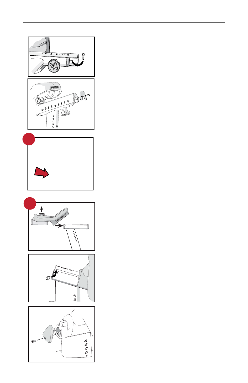
STEP 2: ATTACH THE STABILIZER BARS
Have someone help you tilt the bike forward
(toward the flywheel), remove the rear plastic
shipping guard, then you can attach the
rear stabilizer bar from the underside with
the provided bolts and washers. Line up the
holes in the stabilizer bar with the holes in the
frame. Using the included wrench, tighten
the bolts (with washers) securely. Repeat the
process with the front stabilizer bar.
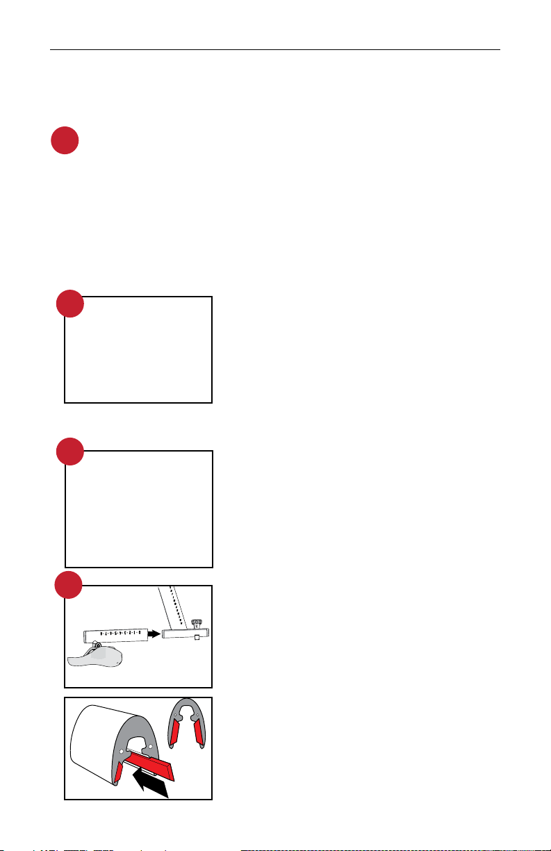
STEP 3: INSTALL THE SEATPOST POP PIN
Install the seat post pop-pin and tighten the
bolt securely making sure that the thin washer
is properly seated and centered between the
pop-pin and the frame boss.
STEP 4: ASSEMBLE THE SEAT POST
1. Slide the seat assembly onto the seatpost,
insuring that the black internal glides remain in
place and are secure inside the slider.
If the glides have slipped out, please make sure
to reinstall them. The glides are shaped to fit in
the orientation as shown and must be installed
by sliding them into the groove from the outside
edge in the correct orientation.
1
2
3
4
1
• Pedals
• Pop pin assembly seat
• Seat slider and saddle
• Seat post
• Tools for assembly and maintenance
provided on the parts card.
• Owner’s manual
SPINNER® BLADE AND SPINNER® BLADE ION OWNER’S MANUAL
www.spinning.com 800.847.SPIN (7746)
17
2. Turn the assembly over and slide the top
portion rearward so that the limiter screw hole
is exposed as shown. Now insert the small 3mm
bolt into the exposed hole and tighten. This
bolt sets the travel limit of the slider.
3. Attach the seat slider end cap using two bolts
and fully tighten with the supplied allen key.
STEP 5: INSERT THE SEAT POST
1. Hold the seatpost in one hand and the pop-
pin with the other. Insert the seat post into the
frame and tighten the pop-pin.
2. Unscrew the knob of the pop-pin and then
pull back on the spring loaded handle.
3. Insert the seatpost into the seatpost glide
and find a general location that lines up with
the pop pin.
4. Now release the lever and pull up or
push down on the seatpost until the pop pin
engages a hole in the seatpost.
5. Tighten the pop pin by turning the handle
clockwise to secure the seatpost.
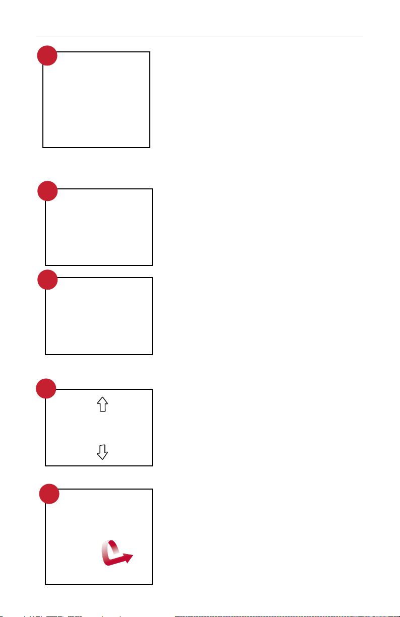
STEP 6: HANDLEBAR ASSEMBLY
1. Hold the headpost in your hands and slide the
handlebar assembly onto the handlebar post
by loosening the fore/aft handlebar knob and
pulling it up to align with the grooves on the
handlebar post.
2. Insert one 3mm bolt into the post on either
side and fully tighten it to set the travel limit.
3. Attach the handlebar post end cap using one
3mm bolt and fully tighten with the hex key.
4. Tighten the fore/aft adjustment knob in any
position before proceeding.
3
2
1
2
3
5
6
© 2021 Mad Dogg Athletics, Inc. All rights reserved.
18
9
STEP8A: INSTALL THE TABLET MOUNT
Locate the 2 bar washers and 4 bolts with
associated washers as shown and align the
holes with the threaded bosses underneath the
center section. Use the allen wrench to tighten
the allen bolts securely.
STEP8B: ATTACH THE TABLET CLAMP
TO THE ARM
Push in and slide down gently to fully engage
the snap locks as shown. Note the orientation
of the tabs and slots.
Pivot bolts can be tightened for a stier angle
adjustment and should always be snug.
Use caution and do not over-tighten these bolts.
STEP 8C: ATTACH THE TABLET
Open holder tabs using two hands and place
tablet securely. Use caution to keep tablet side
controls away from holder tabs.
STEP 9: INSTALL THE HANDLEBARS
The handlebars are installed in the same
fashion as the seatpost. Unscrew, pull out
and hold the handlebar pop-pin. Slide the
handlebar post all the way into the handlebar
tube. Release the handlebar pop-pin and
adjust the handlebars to make sure that the
pop-pin is engaged. Tighten the handlebar
pop-pin securely before riding.
8B
8C
8A
STEP 7: INSTALL THE CRANK
Locate the left side crank and push it onto the
axle in the opposite orientation of the drive side
crank. Give the crank a tap with the hand at that
axle bolt location to make the connection snug.
Now find the 14mm crank bolt on the assembly
card and hand thread the bolt into the axle hole
as far as possible, making sure that the threads
are engaged and the bolt is straight. Use the
supplied 14mm socket wrench to tighten the bolt
clockwise. Make sure it is tight and then snap
the dust cap into the bolt hole.
7

SPINNER® BLADE AND SPINNER® BLADE ION OWNER’S MANUAL
www.spinning.com 800.847.SPIN (7746)
19
STEP 10: INSTALL THE PEDALS
Turn the resistance knob clockwise until the
crank arms are immobilized. Remove the
pedals from the packaging. Install the left
pedal on the left crank. Use the (15mm) multi-
wrench supplied and turn counterclockwise
to tighten. Install the right pedal on the right
crank. Turn the multi-wrench clockwise
to tighten. Remember, pedals are always
tightened by turning the wrench over the
top of the spindle towards the front of the
bike. Be sure both pedals are tightened
securely.
STEP 11: LEVEL THE BIKE
Move the bike to the location where it will be
used. Your Spinner® Bike requires 4 x 6 feet
of floor space for proper operation. Rock the
bike gently to check for wobble. If needed,
use the leveling adjusters under the front
and rear stabilizer bars to steady the bike.
Turn the leveling feet counterclockwise to
decrease the height or clockwise to increase
the height until the bike is stable
11
10 NOTE: The pedal spindles and cranks
are marked “L” (left) and “R” (right).
Left and right are referenced from a
seated position on the bike. Be sure
to install the pedals on the correct
side of the bike.

© 2021 Mad Dogg Athletics, Inc. All rights reserved.
20
WARNING! SAVE THESE INSTRUCTIONS
THE MOMENTUM OF THE FLYWHEEL OF THE BIKE WILL KEEP THE PEDALS TURNING EVEN AFTER
YOU STOP PEDALING OR IN THE EVENT THAT YOUR FEET SLIP OFF OF THE PEDALS. DO NOT
DISMOUNT THE BIKE OR ATTEMPT TO REMOVE YOUR FEET FROM THE PEDALS UNTIL BOTH THE
PEDALS AND THE FLYWHEEL HAVE STOPPED COMPLETELY. FAILURE TO COMPLY MAY LEAD TO LOSS
OF CONTROL AND SERIOUS PERSONAL INJURY.
TESTING THE BIKE
Use this checklist to perform the bike test procedure.
• Re-check all bolts. Make sure that they have been tightened and that
no parts are missing or left over.
• Test the handlebar post and seat post to make sure that they move
freely and that you are able to lock them at dierent positions.
• Check the saddle to make sure that it is level and tight and does not
rotate around or tilt. Tighten and adjust as needed.
• Test the seat slider and handlebar slider (if applicable) for movement
front to rear. Check it by locking it at dierent settings.
• The brake tension (resistance) can be adjusted using the red
resistance knob. Pressing down on the red knob will apply the brake
if you need to stop quickly.
• Adjust the seat post and handlebar post to fit your body.. Refer to the
Guide to Ride or visit www.spinning.com.
• Pedal at a moderate pace and test for proper and smooth resistance
changes while varying the amount of turns on the resistance knob.
• To move the bike after testing is complete, stand in front of the
bike, grasp the handlebars and tip the bike toward you until the
transportation wheels are touching the floor. Roll the bike to the
desired location and then gently lower the rear of the bike back to the
floor. Make sure to adjust the leveling feet so that the bike remains
stable at all times.
This manual suits for next models
1
Table of contents
Other Spinning Fitness Equipment manuals


Popular Fitness Equipment manuals by other brands

Paramount Fitness
Paramount Fitness FL-33 Assembly manual

BH FITNESS
BH FITNESS G400RF Instructions for assembly and use

Sunny Health & Fitness
Sunny Health & Fitness SF-B1516 user manual

Skandika
Skandika Lykke SF-3020 manual

Stamina
Stamina STAMINA Outdoor Strider owner's manual

Hoist Fitness
Hoist Fitness D700 Assembly instructions

Sportplus
Sportplus SPEED RACER user manual

Stairmaster
Stairmaster Core Health & Fitness 10G owner's manual

Huffy
Huffy 211972B owner's manual

Pro Fitness
Pro Fitness 460/3788 Assembly & user instructions

Christopeit Sport
Christopeit Sport VIBRO 5000 Assembly and exercise instructions

JLL
JLL RE100 instruction manual


