Spinning spinner AERO User manual

OWNER’S MANUAL
SPINNER®EDGE
SPINNER®AERO

SPINNER®AERO OWNER’S MANUAL
www.spinning.com 800.847.SPIN (7746)
3
Congratulations on your purchase of a Spinner® Bike. As the creators
of Spinning®and the worldwide leaders in indoor cycling bikes and
programs, we’re here to help you get the most out of every ride. Whether
your goal is to lose a few pounds, stay in shape or train for the next race,
the team at Spinning®is here to help you every step of the way. This
owner’s manual is just the beginning.
Need help? Scan the code to check out our Spinning®
Support Video Library and other useful information about
your new bike and the Spinning®program.
Enjoy the ride.
SPINNER®AERO + SPINNER®EDGE

CONTENTS
For more information about the Spinning® program, Spinning® gear and tips
that will help you make the most of every ride, visit www.spinning.com.
5Safety Precautions
Tools for Assembly
8Bike Information and Specs
10 Parts List
14 Welcome to the Spinning® Program
15 Spinning® Program Safety
17 Your Spinner® Bike
18 Caring for Your Spinner® Bike
19 Bike Assembly
22 Testing the Bike
23 Troubleshooting
24 Brake Pad Replacement
25 Warranty

SPINNER®AERO OWNER’S MANUAL
www.spinning.com 800.847.SPIN (7746)
5
THANK YOU!
Thank you for purchasing your new Spinner® bike. Your bike has been
designed and engineered for safety, durability and to provide a great ride.
The following pages will outline a number of safety precautions and part
diagrams for your reference. It is important to thoroughly read through this
manual and follow all warnings for the best overall experience with your
new ride.
!
• FAILURE TO READ AND FOLLOW THE INSTRUCTIONS IN THIS MANUAL MAY RESULT IN
POSSIBLE SERIOUS INJURY.
• PEDAL SPEED SHOULD BE REDUCED IN A CONTROLLED MANNER.
• FIX YOUR FOOT IN THE PEDAL CAGE OR SPD CLEAT DURING EXERCISING TO
PREVENT UNINTENTED MOVING.
• IT’S IMPORTANT TO ADJUST AND SECURE THE HANDLEBAR AND SEAT TO YOUR
DESIRED POSTION FOR A COMFORTABLE AND SAFE RIDE. DO NOT EXCEED MINIMUM
INSERTION DEPTH MARKS LABELED ‘STOP’ OR ‘MAX’ ON THE HEAD POST AND SEAT
POST VERTICAL ADJUSTMENTS.
IMPORTANT SAFETY PRECAUTIONS
This bike has been designed and constructed for a safe and comfortable
ride. Nevertheless, certain precautions should be taken when using any
piece of exercise equipment. Read the whole manual before assembling and
using the bike. The following safety precautions should also be observed:
1. Keep children and pets away from the Spinner® bike at all times.
Parents and/or those responsible for children should always take their
curious nature into account and the potential of induced hazardous
situations and behavior resulting in accidents. Under no circumstances
should this Spinner® bike be used as a toy.
2. The owner is responsible for ensuring that anyone who uses the
machine is duly informed about the necessary outlined precautions
and proper way to ride.
3. This bike can only be used by one person at a time.
4. Use suitable clothing and footwear. Make sure all laces/cords are tied
and tucked-in so that they are not loose or can be tangled into any
parts of the bike.
5. Turn the resistance knob clockwise until the flywheel is locked when
the bike is not in use.
WARNING

6
6. This bike does not free-wheel. Pedals will continue to spin. Use caution
when slowing and stopping. In an emergency, stop pedaling and push
the resistnace knob down as an emergency brake to stop the pedals and
flywheel from rotating. Uncontrolled spinning pedals can cause injury.
7. If you experience dizziness, nausea, chest pains or any other
symptom while using this bike STOP exercising and SEEK MEDICAL
ATTENTION IMMEDIATELY.
8. Install and ride the bike on a mat that is placed on a level, solid surface
and that has a minimum of 1 meter (39.5”) of unobstructed space around
it on all sides. Adjust the stabilizer feet to make the bike level, secure and
stable on all four feet at the same time.
9. Keep hands well away from any of the moving parts.
10. Wear clothing suitable for riding. Do not wear loose or baggy clothing that
might get caught up in the parts of the bike. Always wear cycling shoes or
athletic shoes with laces tucked in when using the bike.
11. This bike must only be used for the purposes described in this manual.
DO NOT use accessories that are not recommended by Spinning®.
12. Dierently abled people should not use the bike without the assistance
of a qualified person or a doctor. This is not a medical device and
should be used with caution.
13. Do not use the bike if it is not working correctly.
14. Review all warning labels axed to the bike and replace any label
that is damaged, illegible, or removed. Contact customer service at
Spinning.com for replacements.
15. Functional and visual inspections of the bike should be made before
the bike assembly is complete and prior to any ride.
16. Do not exceed the MAX/STOP mark when adjusting the handlebar
post or seat post.
17. Spinning® pedals can cause injury. Pedal speed should be reduced in
a controlled manner.
18. Before using the bike, thoroughly inspect the bike for proper assembly.
19. User must adjust the seat and handlebars to suit the user’s dimensional
requirements. When adjusting, please insure that the bike is stable
and that the resistance knob is turned to clockwise to immobilize the
flywheel. Thoroughly tighen the corresponding adjustment knobs to
insure that the seat and handlebars are secure before riding.
20. This bike should only be used for home (consumer) use and is not
meant for commercial use.
IMPORTANT SAFETY PRECAUTIONS (continued)
SPINNER®AERO OWNER’S MANUAL
www.spinning.com 800.847.SPIN (7746)
7
21. Before every ride please examine brake pad, pedals and drivetrain for
signs of wear. The brake pad is a normal wear item and may need to
be replaced over time.
22. This bike is not suitable for therapeutic use and is for consumer use
only. Consult a physician prior to starting any exercise program.
23. The safety level of the bike can be maintained only if it is examined
regularly for damage and wear (e.g. brake pad, saddle, pedals,
drivetrain, etc).
24. Replace defective or worn components immediately and/or refrain
from using the bike until it is serviced or repaired.
25. Special attention must be paid to all wear components (e.g. brake pads, etc.).
26. Please adjust the handlebar and seat to your best biomechanical
positioning. Incorrect form and/or excessive training may result in injury.
27. Turn the resistance knob counter-clockwise to release the brake
before exercising.
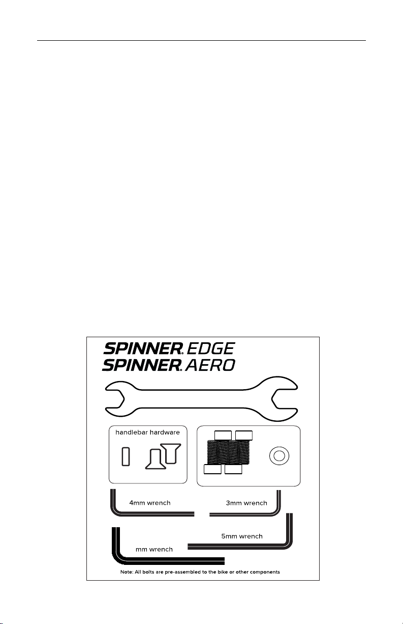
TOOLS INCLUDED FOR SPINNER®BIKE ASSEMBLY
Use the included tools for bike assembly only.
Edge & Aero Blister card
2021.4.25(HW3011)
6
M8X20 Ф8 4PCS
M6X15 M8X16
8
1138mm
1381mm
540mm
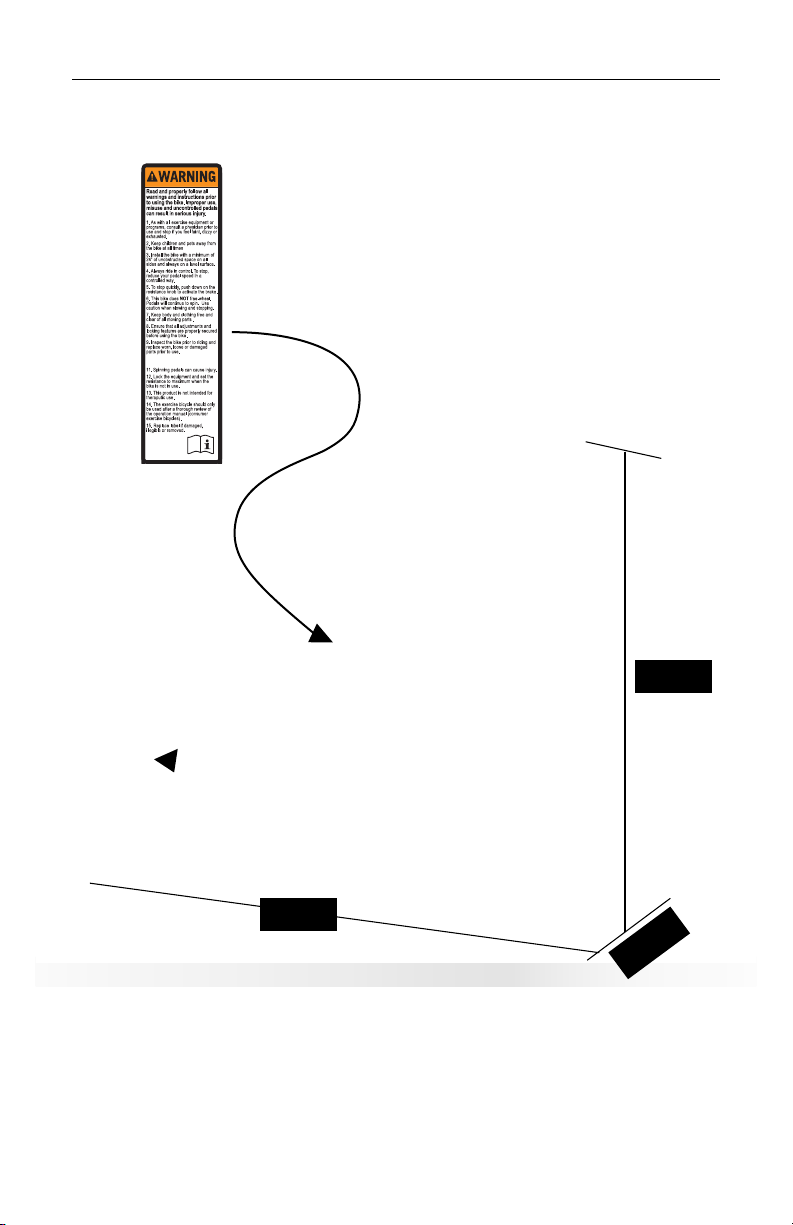
BIKE INFORMATION AND SPECIFICATIONS
SPINNER®AERO - 109 Lbs. | SPINNER®EDGE - 105 Lbs.
10. The maximum user capacity is
275lbx. (125 kgs)
10. The maximum user capacity is
275lbx. (125 kgs)
ASSEMBLED SIZE:
1138mm Long x 540mm Wide x 1381mm Tall (without tablet installed)
WARNING LABEL LOCATION

SPINNER®AERO OWNER’S MANUAL
www.spinning.com 800.847.SPIN (7746)
9
PERIMETER SPACE:
Keep at least 1 meter (39.5”) of clear space around the entire bike
OPERATION AND INSTALLATION PERIMETER
39.5”
1 m

10
SPINNER® AERO PARTS LIST
PART # Description Specification Qty PART # Description Specification Qty
1
Main frame 147 inner chain cover 1
2front stabilizer 148 dropout cover
1
3rear stabilizer 149 front finger guard
EDGE-AERO 1
4handle bar post 150 access door
1
5handlebar 151 front fender
1
6seat post 152 plastic washer
Φ8XΦ4.2X1.5
PVC
2
7seat slider 153 bolt sleeve
PVC 2
8Adjustable Foot
M30X3X25 454 self tapping screw M4X12 2
9End cap
Oval 40X80X2.0 455 Inner Hex socket Bolt M5X20 6
10 Inner Hex socket Bolt
M8X20 456 flat washer Φ5 6
11 flat washer Φ8
Φ8 857 brake arm 1
12 inner hex bolt
M8*38mml. Thread
L15mm.S5 258 plastic brake arm holder 1
13 Moving Wheel
633 259 phillips bolt M5X30 2
14 nylon nut
M8 4 60 nylon nut M5 2
15 61 brake pad
3039 1
16A flywheel cover
contour black 262 EVA cushion 35X24X8 1
17 flange nut M10X1 263 square sheet 37.6X26.6X2.5 1
18 flat washer Φ25.2XΦ10.1X1.5 264 tension knob
Φ10XM10X20
51
19 tension adjuster weldment
265 plastic sleeve 1
20 tension adjuster bracket 266 square plastic sleeve
20X20X12XΦ1
1
1
21 67 compression spring. Φ2.0XΦ17X25 1
22 68 square Copper nut w/ Eva
20X20XM10X1
8
(21)1
23 inner hex bolt
M8X20 469 plastic sleeve Φ18XΦ10X16 1
24 sleeve
Φ34XΦ10.1X7.5 170 hex nut M10 1
25 hex thin nut
M10X1 371 cap nut M10 1
26 thin washer Φ10 472
plastic sleeve for handlebar post
Oval
40X80(25X60(
wadge)
1
27A bearing 6200z 473 plastic sleeve for seat post
Oval
40X80(25X60(
wadge)
1
28 flywheel axle Φ12X161 174 Adjustment knob(big)
M16X1.5X20(
Φ45 )
2
29A Flywheel
L9 175 plastic sleeve(gap) 38SQ x 30SQ 1
30 flywheel sleeve Φ34XΦ10.1X29.5 176 spring knob(small )
M16X1.5X20(
Φ40 )
1
31 pedal JD037
JD037 1set 77 End cap 30X30X1.5 1
32L&R 5008Crank L&R
5008 black-170
reinforced
1set 78 seat 1
33 chain cover
179 inner hex bolt M6X16 1
34 phillips bolt
M5X20 880 inner hex countersunk bolt M8X16 2
35 phillips bolt
M5X10 14 81 water bottle tray 1
36 flange nut
M12X1.5 282 WB Tray Screw Plate 62X37X3.0 1
37 Inner Hex socket Bolt
M8X16 483 Tablet arm 1
38 spring washer
Φ8 484 Bar Bracket 110X12X4.0 2
39 flat washer
Φ8 485 Pivoting Bracket 1
40A belt wheel
Φ220X21 186 Tablet Holder 1
41A belt
5PK1420 187 Hex Socket bolt M6X16 4
42 BB axle
Φ30X145 188 flat washer Ф6 4
43 phillips bolt
M5X50 189 inner hex soket screw M8X16 2
44A Aero rear finger guard
Belt DRIVE 190 wave washer Ф8 2
45 bearing
6005 391 end cap
Oval 20X40X1.5
1
46 C ring
Φ25 192 crank cap 2
Belt system

SPINNER®AERO OWNER’S MANUAL
www.spinning.com 800.847.SPIN (7746)
11
SPINNER®AERO EXPLODED VIEW
©2021 Mad Dogg Athletics, Inc. All rights reserved. Spin®, Spinner®, Spinning®, Spin Fitness®, SPINPower®
and the Spinning logo ® are registered trademarks that are owned by Mad Dogg Athletics, Inc.

12
SPINNER® EDGE PARTS LIST
Part # Part Description Specification Qty Part # Part Description Specification Qty
1
Main frame 147 inner chain cover 1
2front stabilizer 148 dropout cover
1
3rear stabilizer 149 front finger guard
EDGE-AERO 1
4handle bar post 150 access door
1
5handlebar 151 front fender
1
6seat post 152 plastic washer
Φ8XΦ4.2X1.5
PVC
2
7seat slider 153 bolt sleeve
PVC 2
8Adjustable Foot
M30X3X25 454 self tapping screw M4X12 2
9End cap
Oval 40X80X2.0 455 Inner Hex socket Bolt M5X20 6
10 Inner Hex socket Bolt
M8X20 456 flat washer Φ5 6
11 flat washer Φ8
Φ8 857 brake arm 1
12 inner hex bolt
M8*38mml. Thread
L15mm.S5
258 plastic brake arm holder 1
13 Moving Wheel
633 259 phillips bolt M5X30 2
14 nylon nut
M8 4 60 nylon nut M5 2
15 phillips bolt
M5X12 661 brake pad 3039
16 flywheel cover
flat 262 EVA cushion 35X24X8 1
17 flange nut
M10X1 263 square sheet 37.6X26.6X2.5 1
18 flat washer
Φ25.2XΦ10.1X1.5 264 tension knob Φ10XM10X205 1
19 tension adjuster weldment
265 plastic sleeve 1
20 tension adjuster bracket
266 square plastic sleeve 20X20X12XΦ11 1
21 locking nut M33X1counter
threaded 167 compression spring. Φ2.0XΦ17X25 1
22 fixed freewheel 16 168 square Copper nut w/ Eva
20X20XM10X18
(21
)1
23 inner hex bolt
M8X20 469 plastic sleeve Φ18XΦ10X16 1
24 sleeve
Φ34XΦ10.1X7.5 170 hex nut M10 1
25 hex thin nut
M10X1 371 M10 1
26 thin washer Φ10 472 plastic sleevefor handlebar post
Oval
40X80(25X60
(wadge)
1
27 bearing
6000z 473 plastic sleeve for seat post 1
28 flywheel axle Φ12X161 174 Adjustment knob(big)
M16X1.5X20
(Φ45 )
2
29 Flywheel
L1 175 plastic sleeve(gap) 38(30) 1
30 fly wheel sleeve Φ34XΦ10.1X29.5 176 spring knob(small)
M16X1.5X20
(Φ40 )
1
31 pedal JD037
JD037 1set 77 End cap 30X30X1.5 1
32 5008Crank 5008 black-170
reinforced 1set 78 seat 1
33 chain cover
179 inner hex bolt M6X16 1
34 phillips bolt
M5X20 880 inner hex countersunk bolt M8X16 2
35 phillips bolt
M5X10 881 water bottle tray 1
36 flange nut
M12X1.5 282 WB TRAY SCREW PLATE 62X37X3.0 1
37 Inner Hex socket Bolt
M8X16 483 Tablet arm 1
38 spring washer
Φ8 484 Bar Bracket 110X12X4.0 2
39 flat washer
Φ8 485 Pivoting Bracket 1
40 chain wheel
52 186 Tablet Holder 1
41 chain
112 187 Hex Socket bolt M6X16 4
42 BB axle
Φ30X145 188 flat washer Ф6 4
43 phillips bolt
M5X50 189 inner hex soket screw M8X16 2
44 Edge rear finger guard
CHAIN DRIVE 190 wave washer Ф8 2
45 bearing
6005 391 end cap Oval 20X40X1.5 1
46 C ring
Φ25 192 crank cap
Chain System
2

SPINNER®AERO OWNER’S MANUAL
www.spinning.com 800.847.SPIN (7746)
13
SPINNER®EDGE EXPLODED VIEW
©2021 Mad Dogg Athletics, Inc. All rights reserved. Spin®, Spinner®, Spinning®, Spin Fitness®, SPINPower®
and the Spinning logo ® are registered trademarks that are owned by Mad Dogg Athletics, Inc.

14
WELCOME TO THE SPINNING®PROGRAM
Spinning® was born on the road, raised in the studio, and made for your
home. We’ve helped millions of people around the world get into the best
shape of their lives and we can’t wait to ride with you.
The bike is just the beginning! Now you can create your own Spinning®
experience by choosing content and gear for a ride tailored just for
you. Try one of our apps on for size with a free trial for the Spinning®
subscription of your choice.
Spinning® Digital delivers 24/7 access to on-demand rides with rockstar
instructors. Stream rides directly to your favorite Wi-Fi enabled TV,
computer or favorite mobile device. With a diverse selection of instructors,
training styles and durations, you can get the workout you want, whenever
you want – even when you can’t get to the studio.
Spinning® Digital+ is our all-in-one app that combines all the rockstar
instructors and rides from Spinning® Digital with real-time metrics and
tracking. It pairs with your heart rate monitor and your bike (with a power crank
or cadence sensor) to deliver personal metrics and training zones during your
ride! Your performance is tracked with detailed graphs and workout history, so
you’ll see your progress as you crush goals and gain power!

SPINNER®AERO OWNER’S MANUAL
www.spinning.com 800.847.SPIN (7746)
15
SPINNING®PROGRAM SAFETY
• Read all warnings posted on the Spinner®bike. Read this owner’s manual
and follow it carefully before using the Spinner®Aero and Spinner®Edge.
• Consult your physician before beginning this or any other exercise
routine. Not all exercise programs are suitable for everyone. Discontinue
any exercise that causes you discomfort and consult a medical expert.
• Ensure that the adjustment knobs (saddle height, saddle fore/aft and
handlebar height) are properly secured and do not interfere with
range of motion.
• Children under the age of 16 should not ride the Spinner®Aero or
Spinner®Edge.
• Do not insert any object, hands or feet into any openings and do
not expose hands, arms or feet to the drive mechanism or any other
potentially moving parts of the bike.
• The body weight for individuals riding the Spinner®Aero and Spinner®
Edge should not exceed 275 pounds (125 kg).
• Spinner®bikes have a perimeter-weighted flywheel and a fixed gear,
which does not allow riders to coast. This means that, in order to stop,
you must gradually slow your pedaling motion rather than stopping
abruptly. If you need to stop immediately, push down on the red
resistance knob.
• After use, turn the knob clockwise to increase the resistance so that the
pedals will not rotate freely.
• Never turn the pedals or crank arms by hand, unless lubricating the chain
• If at any time you feel dizzy or have diculty breathing, gradually stop
pedaling and carefully dismount the bike.
• Listen to your body, ride at your own pace and set your bike’s resistance
at the level that feels right for you.
• Keep children and pets away from the bike whenever it is in use.
• Stay hydrated. Drink water throughout your ride as needed.
• Always pedal with at least a little resistance on the flywheel.
• Your bike may include a heart rate monitor. The heart rate displayed may
be inaccurate and should be used for reference only

16
• Keep your cadence range between 60 RPM and 110 RPM, depending
upon the terrain. Use proper resistance to keep your pedaling speed
within that range.
• Stay in control by executing all movements and hand positions at a slow
pace before attempting to increase your pedaling speed.
• Focus on form, posture and smooth transitions between movements.
• Always ride with proper footwear. Your bike is equipped with dual-sided
SPD pedals and we recommend cycling shoes for the best connection.
You can purchase cycling specific shoes at spinning.com. Please go to
spinning.com for options.
• Keep shoe laces tucked in and foot straps snug around your shoe. If
your foot does come out of the toe clip, push down on the resistance
knob to stop the flywheel’s motion before placing your foot back in the
pedal cage.
• When setting up the bike, make sure to place it on a level surface,
adjust the leveling feet for stability and leave at least 39.5” of
unobstructed clear space around all sides.
• Care should be taken in mounting or dismouting the exercise bike.

SPINNER®AERO OWNER’S MANUAL
www.spinning.com 800.847.SPIN (7746)
17
SADDLE
DUAL-SIDED PEDALS
CHAIN GUARD
RESISTANCE KNOB
SERIAL LABEL
WARNING LABEL
HANDLEBARS WITH DUAL
WATER BOTTLE HOLDERS
TABLET HOLDER
(TABLET NOT INCLUDED)
SEAT SLIDER
POP PIN (FORE/AFT)
POP PIN (VERTICAL)
FLYWHEEL ADUSTMENT COVER
POP PIN (VERTICAL)
BRAKE ASSEMBLY
PERIMETER WEIGHTED
FLYWHEEL
REAR STABILIZER BAR
WITH LEVELING FEET FRONT STABILIZER BAR
WITH LEVELING FEET
TRANSPORT WHEELS
CRANKSET
YOUR SPINNER®BIKE
The patented Spinner®bike has been specially designed for the Spinning®
program. The Spinner®bike lets you change positions with ease and
includes the following features to create an enjoyable, eective workout:
• A contoured saddle to keep you comfortable and balanced. You can
adjust the saddle horizontally and vertically to create a personalized fit.
• Adjustable handlebars featuring a contoured, tactile grip surface and
an ergonomic design that facilitates proper Spinning® hand positions.
• An adjustable resistance knob to keep you in control of your ride.
Simply turn the dial to add more or less resistance.
• A weighted flywheel to create a non-impact workout and facilitate a
fluid pedal stroke.
Your Spinner®bike uses a direct-drive flywheel that does not allow you to
coast. To stop, decrease your pedaling speed gradually. If you need to
stop immediately, push down on the red resistance knob.

18
CARING FOR YOUR SPINNER®BIKE
MOVING YOUR BIKE
Stand in front of the bike, grasp the handlebars and tip the bike toward
you until the transportation wheels are touching the floor. Be careful about
contacting the tablet holder while moving the bike and do not use it as a
grip or moving handle. Roll the bike to the desired location and then gently
lower the rear of the bike back to the floor.
LEVELING YOUR BIKE
The leveling feet are located on each corner of the front and rear
stabilizer bars. It is important that all four of the leveling feet touch the
ground to keep the bike stable at all times. To adjust, turn the leveling feet
counterclockwise to decrease the height or clockwise to increase the
height until the bike is stable.
ADJUSTING AND LEVELING YOUR SADDLE
If you experience saddle discomfort while riding or sitting on your bike,
the angle can be adjusted by loosening the 14 mm nuts located under the
saddle. Be sure to re-tighten the nuts after making your angle adjustment
and before riding your bike.
PREVENTING RUST
After each use, raise the handlebar post and seat post to the highest
settings to allow any moisture to evaporate. Using an absorbent cloth,
wipe all areas where moisture can settle.
PROTECTING YOUR SPINNER®BIKE’S FINISH
After each ride, protect your bike’s finish by wiping it down with a damp
cloth. You may use bike cleaner such as SPINTECH® Fitness Equipment
Polish, but do not use de-greasers or harsh cleaning products. When
cleaning your bike, be sure to keep your hands and fingers clear
of a moving drivetrain. Never spray any cleaners onto the frame or
components. Instead, spray a soft cloth with a diluted mixture of Simple
Green (or equivalent) and wipe the bike down. Thoroughly dry the bike
with a separate towel.
PEDALS
Check the pedals weekly to ensure that the threads are completely
tightened and the cleat retention is tailored to your riding style. If the
pedals have become loose, tighten the threads with the supplied pedal
wrench to ensure that they are securely attached. (Drive side tightens
clockwise, non-drive side tightens counter-clockwise.)

SPINNER®AERO OWNER’S MANUAL
www.spinning.com 800.847.SPIN (7746)
19
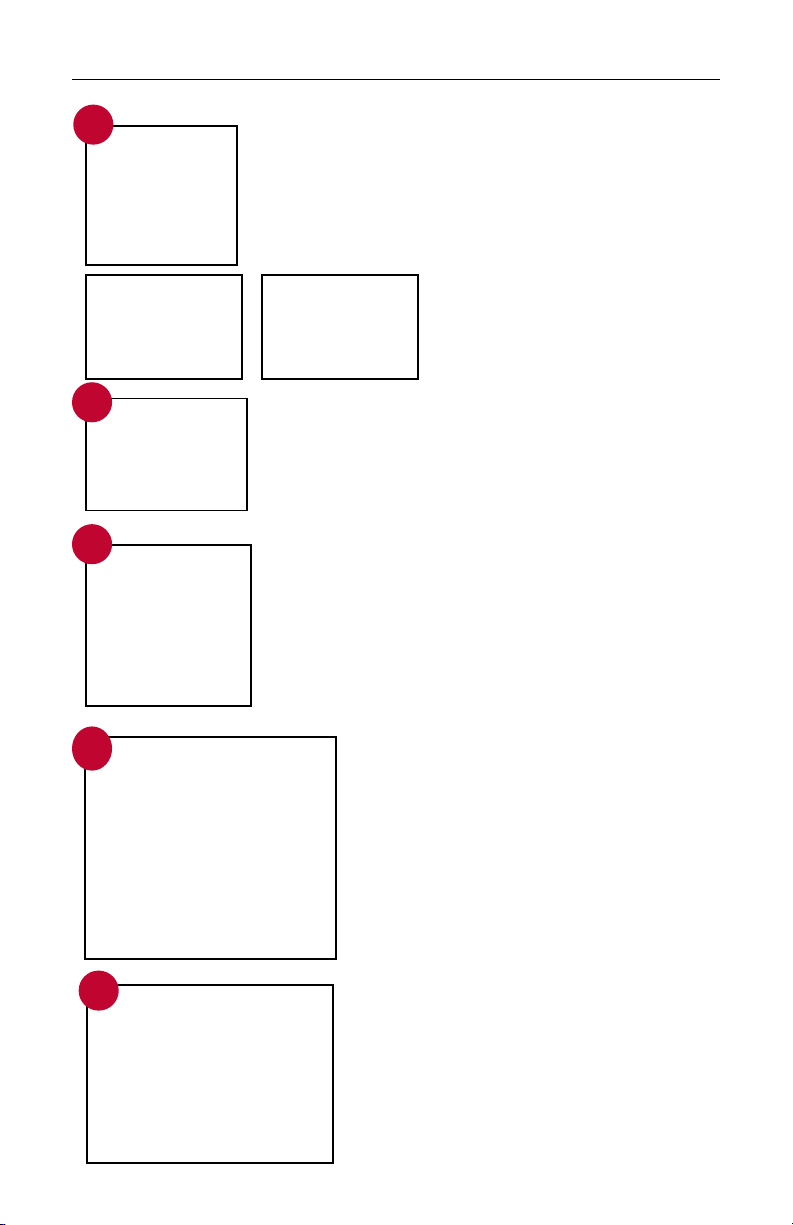
SPINNER®BIKE ASSEMBLY
STEP 1: Unpack the carton
Open the shipping carton and remove all of the parts. Make sure that
the following parts are included and that no damage has occurred
during shipping:
• Bike frame with flywheel
• Front stabilizer bar with
transportation wheels
• Rear stabilizer bar
• Handlebars
• Handlebar post
• Pedals
• Seat slider and saddle
• Seat post
• Blister card for assembly and
maintenance includes: Multi-wrench,
3mm / 4mm / 5mm / 6mm Allen
wrenches, each 1pc. M6X15 inner
hex bolt 1pc., M8X16 inner hex bolt 2pcs,
hex socket bolt 4pcs, flat washer 8 pcs.
• Owner’s manual
• Tablet holder set
• Tablet arm Set (with assembly bolts)
• Dual water bottle holder set (with
assembly bolts
STEP 2: ATTACH THE STABILIZER BARS
Have someone help you tilt the bike forward
and stabilize it while you remove the rear
plastic shipping guard. Lift the back of the
bike and remove the front plastic shipping
guard . It is normal to see cracking in the
shipping guards as they protect the frame
in transit. Have someone help you tilt the
bike forward (toward the flywheel) so that
you can attach the rear stabilizer bar from
the underside with the provided bolts and
washers. Line up the holes in the stabilizer
bar with the holes in the frame. Using the
included wrench tighten the bolts (with
washers) securely. Repeat the process with
the front stabilizer bars.
STEP 3: INSTALL THE SADDLE
While holding and pulling back the seat post
pop-pin knob, slide the seat post into the
seat tube. Release the pop-pin knob. Adjust
the seat post to make sure the pop-pin is
properly engaged. Tighten the seat post
pop-pin knob securely. Now unscrew, pull
out and hold the seat slider pop-pin knob.
Slide the seat slider all the way into the seat
tube. Release the seat slider pop-pin knob.
Adjust the seat slider (fore/aft) to make sure
the pop-pin is engaged. Tighten the seat
slider pop-pin knob securely.
3
1
seat slider
seat post
pop-pins
knobs
2
20
STEP 4B: INSTALL WATER BOTTLE HOLDER AND
THE TABLET MOUNT
Locate the 2 bar washers and 4 bolts as shown and
align the holes with the threaded bosses underneath
the center section. Use the allen wrench to tighten
the allen bolts securely.
STEP 4C: ATTACH THE TABLET CLAMP TO THE ARM
Push in and slide down gently to fully engage the
snap locks as shown. Note the orientation of the tabs
and slots.
Pivot bolts can be tightened for a stier angle
adjustment and should always be snug.
Use caution and do not over-tighten these bolts.
4
5B
6
STEP 4A: HANDLEBAR ASSEMBLY
Insert the chrome handlebar post onto the threaded
handlebar stem making sure the holes line up. Using
a 5mm Allen wrench, insert, then tighten the two
large bolts on the front of the bar. Now insert, then
secure, the 3mm bolt at the rear of the post.
Check to make sure that all the
bolts are tightened securely
before proceeding.
5A
STEP 4D: INSTALL THE HANDLEBARS
Install the large handlebar pop-pin knob
into the frame head tube several turns
only, then pull out and hold the handlebar
pop-pin knob. Slide the handlebar post all
the way into the handlebar tube. Release
the handlebar pop-pin knob. Adjust the
handlebars to make sure that the pop-pin
is engaged. Tighten the handlebar pop-pin
bolts securely before riding.
STEP 4E: ATTACH THE TABLET
Open holder tabs using two hands and
place tablet securely. Use caution to
keep tablet side controls away from the
holder tabs.
7
Other manuals for spinner AERO
1
This manual suits for next models
2
Table of contents
Other Spinning Fitness Equipment manuals


Popular Fitness Equipment manuals by other brands


Independence
Independence 335 Instruction manual & parts list

FRENCH FITNESS
FRENCH FITNESS FF-MIC4 Assembly manual

Medisana
Medisana AM 880 instruction manual

Christopeit Sport
Christopeit Sport AX 6000 Assembly and exercise instructions

skillworx
skillworx High Parallettes manual

XM Fitness
XM Fitness XM100 manual