IM-P117-36 ST Issue 1
8
3. Installation
Note: Before actioning any installation observe the ‘Safety information’ in Section 1.
Referring to the Installation and Maintenance Instructions, name-plate and Technical
Information Sheet, check that the product is suitable for the intended installation:
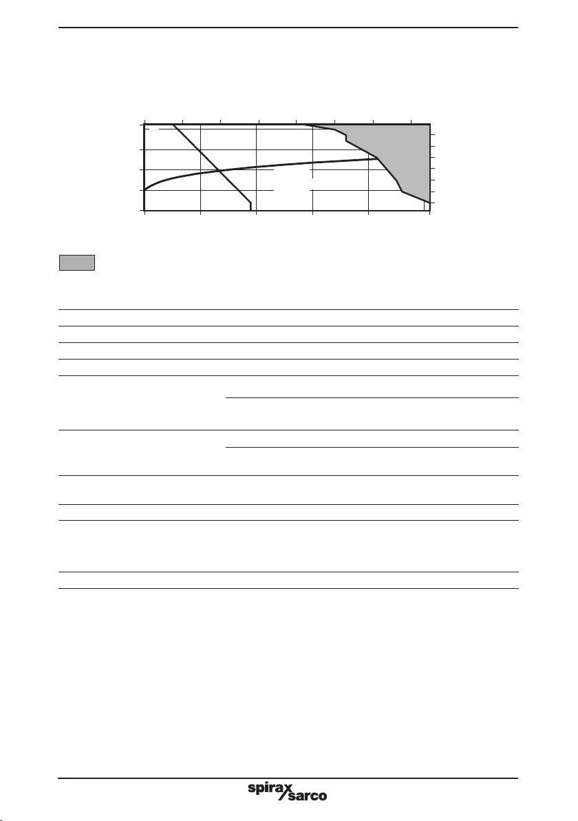
3.1 Check materials, pressure and temperature and their maximum values. If the maximum
operating limit of the product is lower than that of the system in which it is being fitted,
ensure a safety device is included in the system to prevent overpressurisation.
3.2 Determine the correct installation situation and the direction of fluid flow.
3.3 Remove protection covers from all connections and protective film from all name-
plates, where appropriate, before installation on steam or other high temperature
applications.
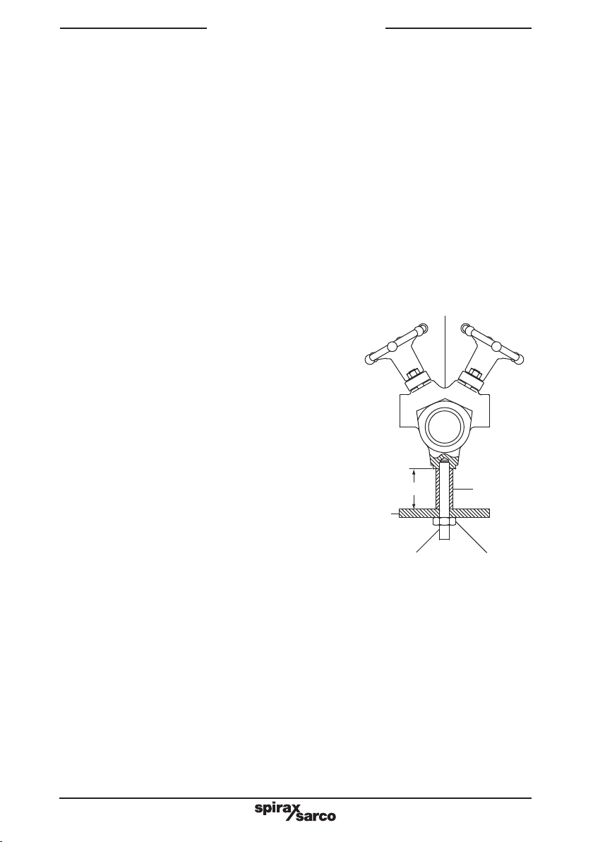
3.4 General information - The manifold has been designed for vertical installation. Ensure
that there is sufficient access to the handwheel to allow proper operation. The back is
provided with M12 threaded connections for attaching to a supporting structure.
For ease of insulation it is recommended that spacers are fitted to give the manifold
a stand-off of at least 50 mm.
For convenience the following sets of
mounting kit are available:
- A single set comprising 2 off each stud,
nut and spacer suitable for installing one
MSC04-P or N and MSC08-P or N.
- A single set comprising 4 off each stud,
nut and spacer suitable for installing
one MSC12-P or N.
- A multiple set comprising 12 off each
stud, nut and spacer suitable for installing
6 x MSC04-P or N, 6 x MSC08-P or N
and 3 x MSC12-P or N.
After installation it is recommended that
the manifold is insulated to minimise
radiated heat losses and to protect
personnel from burn risks. This is most
easily done using the optional insulating
jacket.
Note: If the trap draining the manifold is
to discharge to atmosphere ensure it is
to a safe place, the discharging fluid may
be at a temperature of 100°C (212°F).
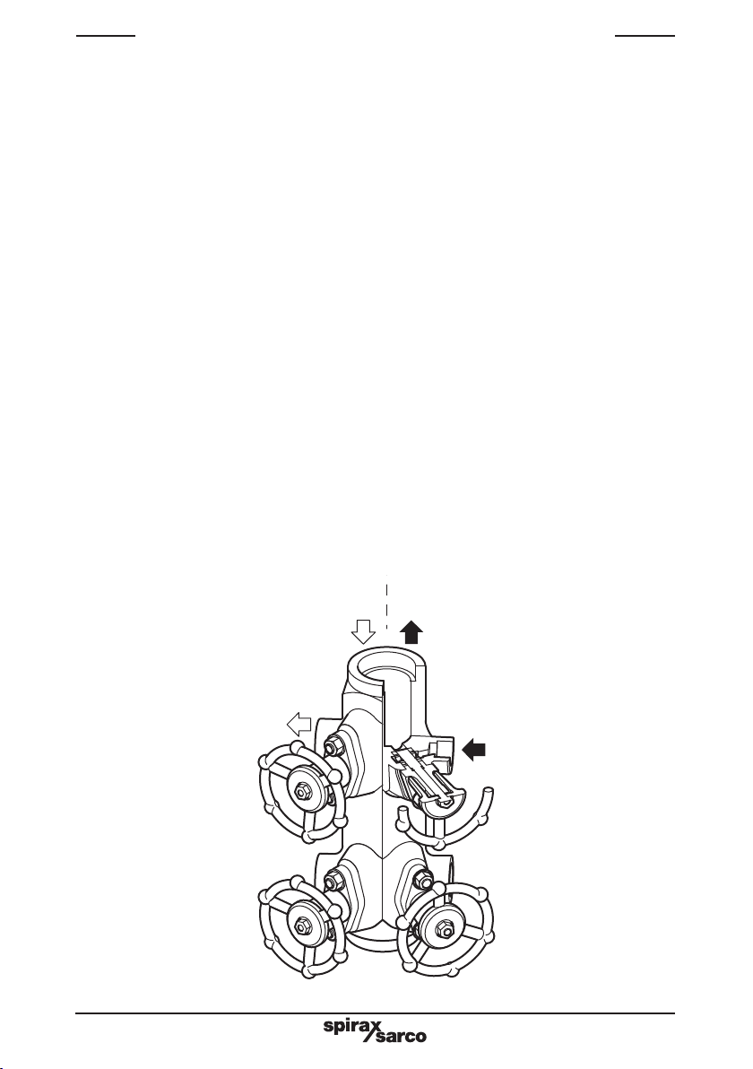
3.5 Steam distribution duty - The recommended installation is with the steam inlet
connection at the top of the manifold. A trap set should be fitted to the bottom.
The discharge from this trap set should ideally be returned. If it is to be discharged
to atmosphere we recommend that a diffuser is fitted.
3.6 Condensate collection duty - The recommended installation is with the condensate
outlet at the top. The bottom of the manifold should be fitted with a stop valve for
blowdown purposes. Again, we recommend that a diffuser is fitted.
3.7 Pipeline welding - When installing any welding should be carried out to an approved
procedure of a recognised standard.
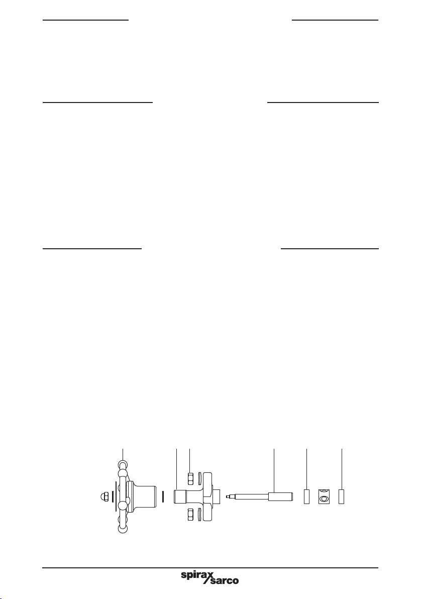
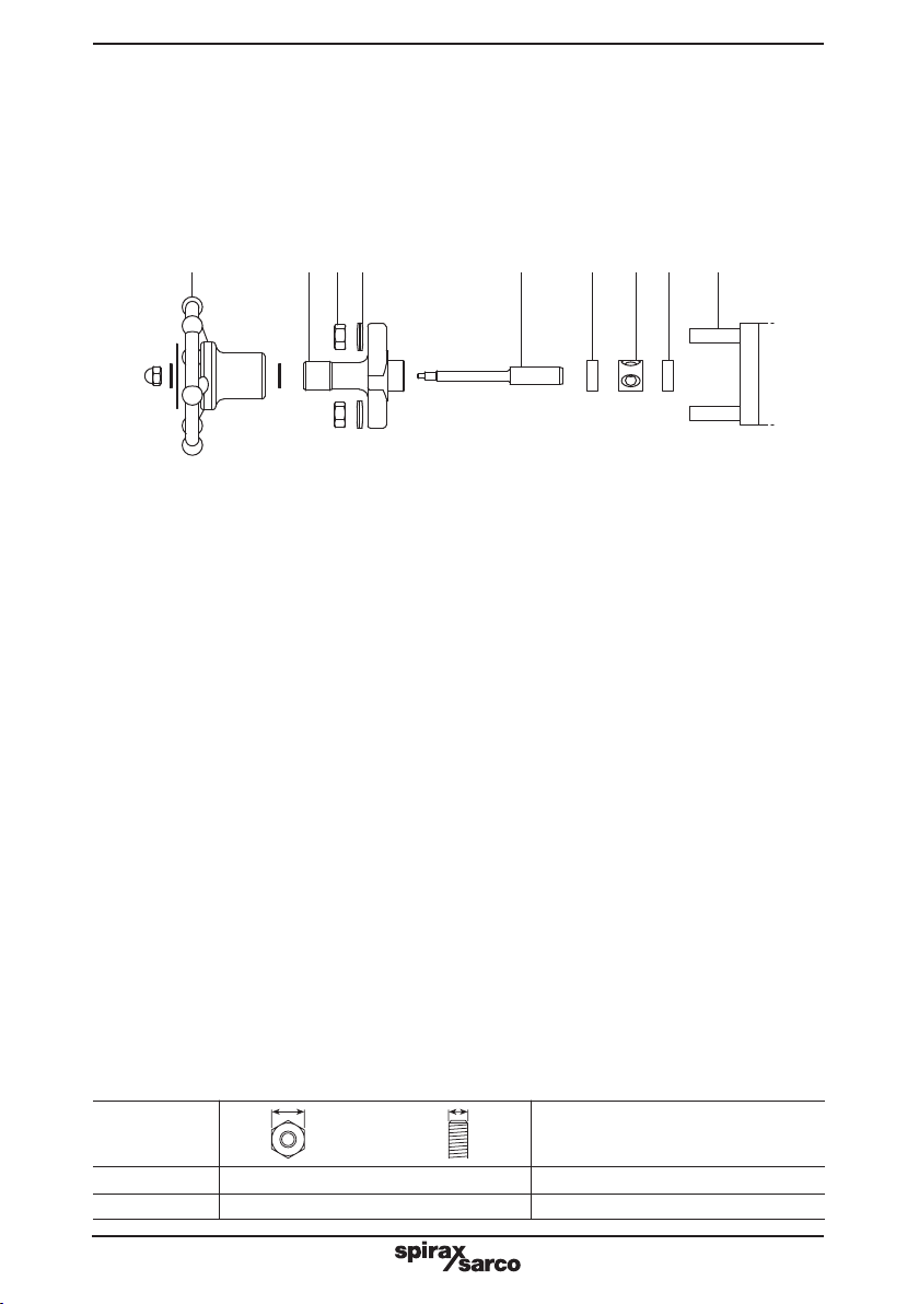
Fig. 2 Installation view
Structural
steelwork
M12 stud M12 nut
Spacer
MSC-P or MSC-N manifold
50 mm