Spirax Sarco M750 User manual

IM-P332-07 MI Issue 2 1
M750
Display Unit
Installation and Maintenance Instructions
IM-P332-07
MI Issue 2
3320250/2
1. General
safety information
2. General
product information
3. Installation
4. Commissioning
5. Spare parts
6. Fault finding
Printed in the UK © Copyright 2004
1234
Vac Tag No
888888

IM-P332-07 MI Issue 22
Your attention is drawn to any National or local regulations. Safe operation of the
product depends on it being properly installed, commissioned and maintained by a
qualified person in compliance with these operating instructions.
The product is designed and constructed to withstand the forces encountered during
normal use. Use of the product for any other purpose, or failure to install the product
in accordance with these Installation and Maintenance Instructions, could cause
damage to the product, will invalidate the marking, and may cause injury or fatality
to personnel.
Warning
ThisproductcomplieswiththerequirementsofElectromagneticCompatibilityDirective
89/336/EEC by meeting the standards of:
-EN 61326: 1997 Electrical equipment for measurement, control and
laboratory use - EMC requirements. Immunity to industrial locations Annex A.
-Emissions to Class A.
The following conditions should be avoided as they may create interference above the
limits specified in EN 61326: 1997:
-The product or its wiring is located near a radio transmitter.
-Cellular telephones and mobile radios may cause interference if used within
approximately 1 metre (39') of the product or its wiring. The actual separation
distancenecessary willvary accordingto thesurroundings ofthe installationand the
power of the transmitter.
Warning
Isolate the mains supply before unplugging the display unit since hazardous voltages
will be exposed on the unit base.
If this product is not used in the manner specified by this IMI, then the protection
provided may be impaired.
1. General safety information

IM-P332-07 MI Issue 2 3
TheM750 display unit isa highly accurate andstable digital process indicatorthat accepts
all commonlyused processsignals. Theunit can beused 'stand alone'or, with theModbus
serial communications, as part of a larger system.
Option Pods may be plugged into the M750 base unit, without the need for dismantling or
re-calibration, to allow the output from the M750 to be tailored to a specific application.
Option Pods are available for relay outputs and/or an isolated 4-20 mA re-transmission. It
is possible to have two relay pods attached to the base unit, but only one 4-20 mA
retransmission pod. Once an option pod is added to the M750, the unit will automatically
detect it and will prompt the user for the appropriate data during commissioning.
Equipment delivery and handling
Each carton should be inspected at the time of delivery for possible external damage. Any
visible damage should be recorded immediately on the carrier’s copy of the delivery slip.
Eachcartonshould be unpacked carefully and itscontentscheckedfordamage. If it is found
that some items have been damaged or are missing, notify Spirax Sarco immediately and
provide full details. In addition, damage must be reported to the carrier with a request for
their on-site inspection of the damaged item and its shipping carton.
Storage
If a flowmeter is to be stored for a period prior to installation, the environmental storage
conditions should be at a temperature between -50°C and +85°C (-58°F and +185°F), and
between 10% and 90% relative humidity (non-condensing).
2. General product information
1234
Vac Tag No
888888
Fig. 1 Display unit

IM-P332-07 MI Issue 24
131 (5.16") (Behind bezel)
11
(0.43")
Plan elevation Option pod
53.5
(2.11")
16
(0.63")
43.5
(1.71")
13.5
(0.53")
19.5
(0.77")
140 (5.5")
10 (0.39")
(Ma imum panel thickness)
Option pod
Clamping screw
Panel clamp
Side elevation
Front elevation
Rear elevation
1234
Vac Tag No
96 (3.78")
48
(1.89")
888888
3. Installation
Warning - This Section must be used by competent personnel only. If this equipment is not
installed in accordance with these instructions, protection against electrical hazards may be
impaired. It is the responsibility of the installer to install this equipment in accordance with the
relevant code of practice (for the installation of instrumentation used in the process control
systems), issued by a recognized local body.
3.1 Mechanical installation
Ensure that the panel has sufficient depth to install the M750 and its wiring, including the
space required to withdraw the wiring connectors.
Panel cut out 92 mm (3.62") x 45 mm (1.77")
Mounting - This equipment is classed as permanently connected equipment. Hazardous
voltages may be present on the terminals of this equipment. The equipment must be panel
mountedinto a suitable enclosure,which provides atleast IP20 protection behindthe panel.
The maximum panel thickness is 10 mm (0.39"). The instrument case has an integral gasket
which forms a seal when the instrument is tightened against the panel. The panel should be
clean, smooth and at least 1.6 mm (0.06") thick for the seal to be effective.
Warning - Use only the retaining screws provided to clamp the instrument to the panel
(screwsmustbetightenedsufficientlytoeffectasealbutmustneverbeovertightened).
Fig. 2 Dimensions (approximate) in mm and inches

IM-P332-07 MI Issue 2 5
The power supply rating will be indicated on the top of the instrument. Ensure it is correct for
the application.
Cables are retained by screws. Ensure that the exposed section of the cable is fully
inserted and that no loose strands are exposed. 600 Vrms cable 0.5 mm² (0.02"²) to
1.5 mm² (0.06"²) core should be used.
Signal Input/Outputs - All signal input, output and communication terminals and associated
internalcircuitry are intendedforoperation at voltagesless than 40 Vdc.These circuits, which
may become accessible during normal operation, must only be connected to signals
complying with the requirements for Safety Extra Low Voltage (SELV) circuits.
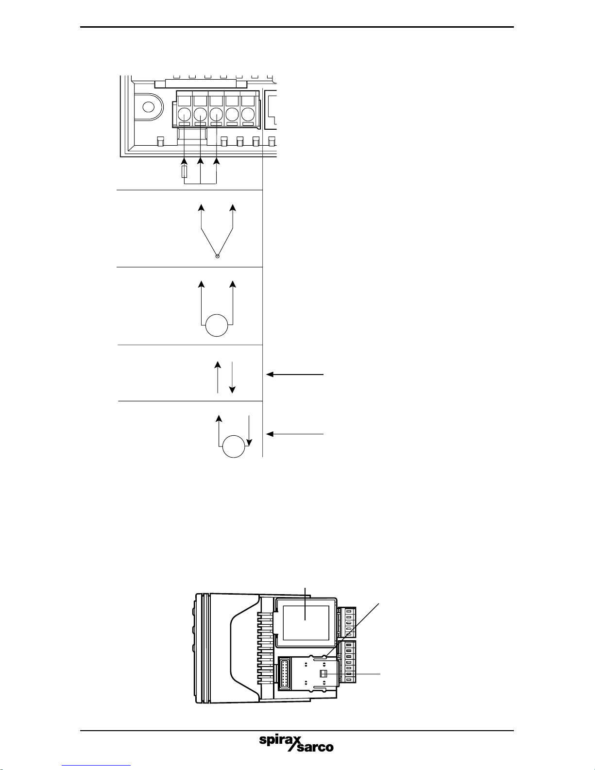
Sensor connections - All sensor connections are made via the five way 'fast wiring' socket
at the rear of the unit (wire size 0.5 mm² (0.02"²) to 1.5 mm² (0.06"²)).
Note: Screened cable is recommended for thermocouple, RTD and voltage input wiring runs
over 10 metres (32.3 ft) long.
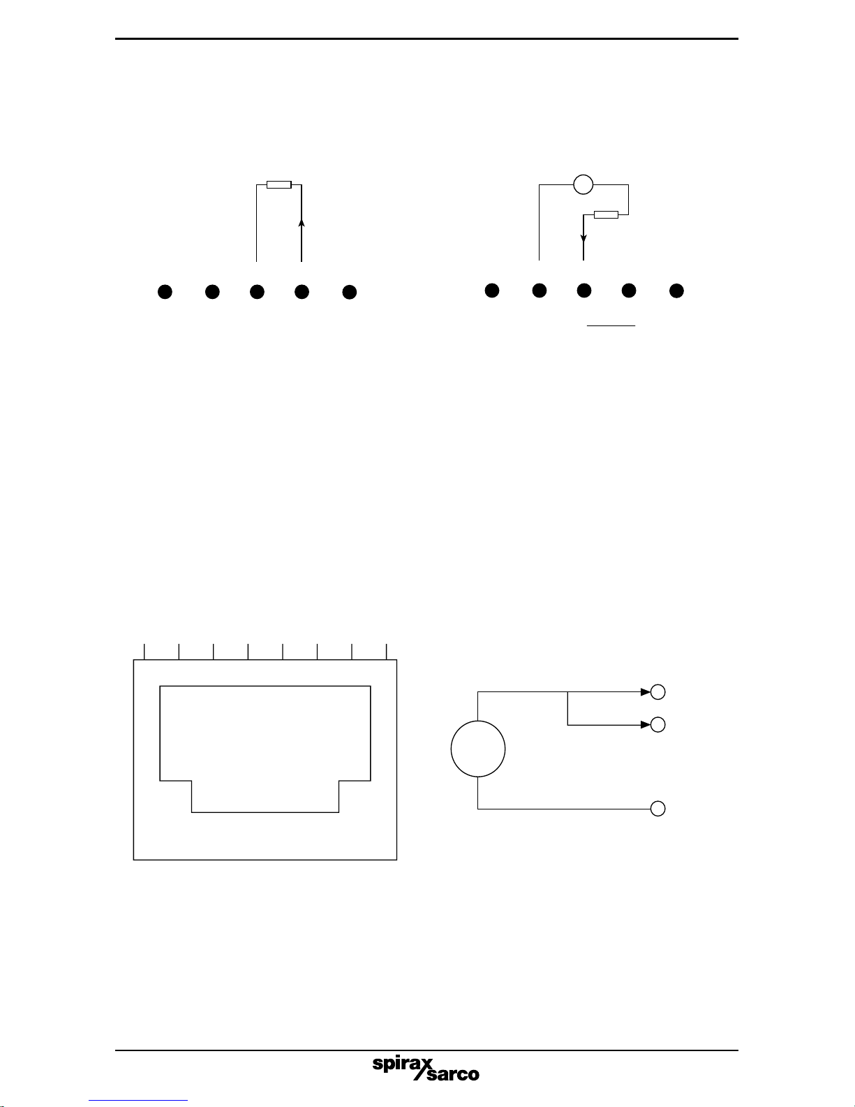
To make a connection: insert a small screwdriver blade into the tension clamp orifice,
(1, Figure 4), push and twist to deflect clamp into the open position. Do not lever the
screwdriverasthismayforcetheconnectorbodysideways.Insertthestrippedwiresufficiently
into (2) then remove the screwdriver. Ensure no loose wire strands protrude.
To avoid connector blocks' being plugged into the wrong connector a polarisation kit is
included. This should be used to ensure that the sensor connector block can only be plugged
into the sensor connections and the Pod connector blocks can only be plugged into their
appropriate connectors.
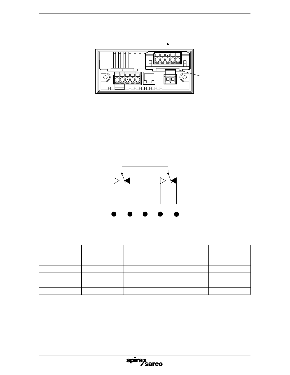
(+)L (-)N
E ternal
1 amp
fuse
Fig. 3
3.2 Electrical installation
All connections are made to sockets, which are removable for ease of maintenance and
wiring. Cable size should be between 0.5 mm² (0.02"²) and 1.5 mm² (0.06"²).
Supply-Thesupplyterminalsandassociatedinternalcircuitryareisolatedfromallotherparts
of the equipment in accordance with BS EN 61010-1, for connection to an Installation over-
voltage Category II supply, (pollution degree 2). The supply voltage and frequency must
remain within the limits stated on the product label.
The mains supply to the unit must be protected by an external 1 amp fuse
(see Figure 3) and a suitable switch or circuit breaker must be located close to the
equipment, in order to isolate the supply.
1
2
Fig. 4

IM-P332-07 MI Issue 26
42
2431+5
-
RTD
T/C
Voltage
Current
Active
(For self- powered
4 - 20 mA devices)
+
-
Current
Passive
(For un- powered
4 - 20 mA devices)
31+5
-
4231
+
5
-
42315
TX
V
24315
3.3 Option pods - Installation
Installing pods
Disconnect the power from the unit before adding/removing a Pod.
Caution:- Referring to Figure 6, Slot 1 (alarms 1A and 1B) should be positioned on the left side
of the unit looking from the front to correspond to the front panel alarm indicator; Slot 2 (alarms
2A and 2B) is positioned on the right.
ToinstallanOption Pod, slide back the covertoexposetheconnector socket and plug in thePod.
Warning: Remove power to the unit before
connecting the sensor input.
Thisis for use with4-20 mA devicesthat
are self-powered or powered from an
external power supply.
This will provide a voltage supply
(19 V @ 25 mA) to power the sensing
device, for example a DIVA steam
flowmeter or M610/M640 differential
pressure transmitter
Fig. 5 Sensor connection wiring details:
Fig. 6 Installing an option pod
Toinserttheoption pod, slide
the cover back unit until it
engages in the position
shown.
Slot 2
Slot 1

IM-P332-07 MI Issue 2 7
To remove an Option Pod, press the bar below the Pod connector and at the same time pull the
Pod upwards.
Alarm/relay states
Thealarmandrelaystatescanbeconfiguredwithintheconfigurationmodeviathe'InVrt'setting.
The'InVrt'settingreferstotherelaysenseduringpoweredoperation.Allotherrelayoutputmenu
settings refer to the alarm state. When in alarm, the relevant front panel LED is lit.
Power Alarm status InVrt setting Relay Relay
position (A) position (B)
Off X X 3-5 3-2
On Not in alarm nOnInV 3-4 3-1
On In alarm nOnInV 3-5 3-2
On Not in alarm InVErt 3-5 3-2
On In alarm InVErt 3-4 3-1
Figure 9 overleaf illustrates, diagrammatically, the pod wiring diagrams.
Dual relay pod
The relay terminals and associated internal circuitry are isolated from all other parts of the
equipment in accordance with BS EN 61010-1, for connection to an Installation over-voltage
Category II supply (pollution degree 2). The relay operating voltage and current must remain
within the limits stated.
Cable used should be 600 Vrms cable between 0.5 mm² (0.02"²) and 1.5 mm² (0.06"²)
The relay pod has two 'change over' relays with a common connection, see Figure 8.
Note: Any circuit with an ac potential greater than 33 Vrms and 46.7 V peak must be protected
with a 5 A(T) fuse when connected to this pod.
12345
NO
NC
NO
Common
NC
1. Lift pod upwards.
2. Press and hold the
back of the cover
Fig. 7 Removal of option pod
Fig. 8

IM-P332-07 MI Issue 28
Fig. 9 Pod wiring diagram
12345
NO
NC
NO
Common
NC
12345
NO
NC
NO
Common
NC
12345
NO
NC
NO
Common
NC
12345
NO
NC
NO
Common
NC
12345
NO
NC
NO
Common
NC
Power off
Power on
Relay sense set to 'nOnInV'
Unit not in alarm
Power on
Relay sense set to 'nOnInV'
Unit in alarm
Power on
Relay sense set to 'InVErt'
Unit not in alarm
Power on
Relay sense set to 'InVErt'
Unit in alarm

IM-P332-07 MI Issue 2 9
Communication/digital Input
Thisprovidestheuserwitheither4or2wireRS485 serial communicationstogetherwithtwo
digital inputs. The digital inputs are available to allow the user to reset latched alarms or
reset totals. Connections are made via a RJ45 connector. A one metre interface is supplied
with the unit to allow the user to connect the OPT-3600/series DIN rail mounted breakout
board (Figure 11).
To activate, apply a voltage between 5 and 24 V.
Maximum current per channel = V/1 600 amps.
The discreet inputs are reverse-connection and over-voltage protected.
Isolated 4-20 mA re-transmission pod
The re-transmission pod (when fitted) is designed to provide 0-10 mA, 0-20 mA or 4-20 mA
output in active or passive modes. The output can be any proportion of the display range. The
pod can be used in two modes (see Figure 10).
12345
12345
V
+
-
R load Passive (Sink)
R load
Maximum load = 1 K (V - 2)
R load < K
22
and V max = 30 V
Ω
RJ45
DIS CO
DIS1
CO S CO
DIS2
+TX
-RX
-TX
+RX
DIS 1
DIS 2
DIS COM
+
-
5 V to
24 V
Fig. 10
Fig. 11

IM-P332-07 MI Issue 210
T
R
Rt
-T
+T
-R
+R
T
enable
R
GWG
T
R
Rt
-T
+T
-R
+R T
enable
R
GWG
T
R
-T
+T
-R
+R
T
enable
R
GWG
100 W 100 W
1/2 W 1/2 W
T
R
-T
+T
-R
+R
T
enable
R
GWG
T - Transmitter
R - Receiver
-Circuit ground or
circuit common
Protective ground or
frame ground
-
GWG - Green wire ground
or power system ground
Rt - Termination resistor
ASTER SLAVE
SLAVE SLAVE
100 W 100 W
1/2 W 1/2 W
100 W 100 W
1/2 W 1/2 W
100 W 100 W
1/2 W 1/2 W
Fig. 12 Typical RS-485 two-wire multi-drop network
RS-485 two-wire installation
-Connect the positive terminals (+Tx and +Rx) together at the M750.
-Connect the negative terminals (-Tx and -Rx) together at the M750.
-Use a EIA RS 485 screened with twin twisted pair communication cable (e.g.: Alpha
wire, part 6413). Note: Twisted pair cable should not be required for short lengths of
cable <
1.5
m (<
5
ft). Standard screened cable should suffice.
-Using one twisted pair, connect the M750 positive terminals to the positive wire of bus and
the negative terminals to the negative wire of the bus.
-Connect the common (coms com) to the bus common using the second twisted pair.
Note: The common connection is recommended, but should not be necessary for short
lengths <
30
m (<
100
ft).
-Considerterminatingthe twofurthestendsofthebus tomatchthetransmissionline impedance
using termination resistors - 120 Wis a common value, but ideally the line impedance should
be matched to each individual installation. Note: Termination for short lengths of cable
should not be necessary <
300
m @ 9
600 Baud (<
1
000
ft @ 9
600 Baud).
1
200
m (4
000
ft)
Termination resistors at both ends only

IM-P332-07 MI Issue 2 11
RS-485 four-wire installation
-Use an EIA RS 485 screened triple twisted pair communication cable (e.g.: Alpha
wire, part 6414). Note: Twisted pair cable should not be required for short lengths of
cable <
1.5
m (<
5
ft).
-Using one twisted pair, connect the M750 + Tx and -Tx terminals to the +Rx and -Rx wires of
the bus respectively. Standard screened cable should suffice.
-Using the other twisted pair, connect the M750 +Rx and -Rx terminals to the +Tx and -Tx wires
of the bus respectively.
-Connect the common (coms com) to the bus common using the third twisted pair.
Note: The common connection is recommended, but should not be necessary for short
lengths <
30
m (<
100
ft).
T
R
-T
+T
-R
+R
GWG
T
enable
R
SLAVE
T
R
-T
+T
-R
+R
GWG
T
enable
R
SLAVE
T
R
Rt
-T
+T
-R
+R
T
enable
R
GWG
Rt
ASTER
T
R
Rt
-T
+T
-R
+R T
enable
R
GWG
Rt
SLAVE
100 W 100 W
1/2 W 1/2 W
100 W 100 W
1/2 W 1/2 W
100 W 100 W
1/2 W 1/2 W
100 W 100 W
1/2 W 1/2 W
T - Transmitter
R - Receiver
-Circuit ground or
circuit common
Protective ground or
frame ground
-
GWG - Green wire ground
or power system ground
Rt - Termination resistor
Fig. 13 Typical RS-485 four-wire multi-drop network
1
200
m (4
000
ft)

IM-P332-07 MI Issue 212
3.4 Technical data (@ 20°C)
General 90-264 Vac 50/60 Hz
90-253 Vac 50/60 Hz for compliance with LVD and UL
Power supply BS EN 61010-1 for connection to an installation over-voltage
Category II supply
Pollution degree 2
Power consumption 10 VA (worst case)
Isolation (tested to) 500 V
Supply to I/O 3 750 V
BS EN 61010-1 for connection to an installation over-voltage
Relay supply Category II supply
Pollution degree 2
IP rating IP65 (front panel only)
Ambient operating temperature -30 to +60°C (-22°F to +140°F)
Environmental Ambient storage -50 to +85°C (-58°F to +185°F)
Ambient humidity 10 to 90% RH
EMC: Emissions and immunity BS EN 61326
Safety BS EN 61010-1
Universal input types Sensor Sensor range and linearisation
mA 4-20 mA, ±20 mA, ±10 mA
RTD Pt 100, NI 120, custom
Sensor and T/C K,J,T,R,S,B,N,L,B,E,Custom*
Sensor range mV ±100 mV
and linearisation Volts ±10 V, ±5 V, 1 - 5 V, ±1 V
Any span within the range can be
Minimum span selected, but the recommended
span is > 10% of range.
Basic accuracy 0.05% FS ±0.05% of reading
Current input Thermal drift 200 ppm/°C
Input impedance 20 W
Linearity Linear, X1/2,X3/2,X5/2, custom*
A 19 V @ 25 mA isolated power supply is provided to power the current loop.
*Custom can be up to 60 co-ordinate pairs or up to 7 segments of 15th order polynomial.
Output options
Dual relay alarm pod
Two independent mains rated relay outputs
Contacts 2 x changeover relays with common
Ratings ac dc
Maximum load 5 A@250 V 5 A@30 V (inductive load 2 A)
Maximum power 1 250 VA 150 W
Maximum switching 253 volts 125 volts
Electrical life 105operations at rated load
Mechanical life 50 million operations
Termination Standard 5 way tension clamp connector

IM-P332-07 MI Issue 2 13
Isolated 4-20 mA re-transmission pod 0-10 mA (Active or Passive)
Ranges 0-20 mA (Active or Passive)
4-20 mA (Active or Passive)
Minimum current output 0 mA
Maximum current output 23 mA
Accuracy 0.07% FS
Resolution 1 part in 30,000
Maximum output load Active 1 K W
Passive [(Vsupply - 2)/20] K W
Maximum external supply voltage 30 V (Passive mode)
Voltage effect 0.2 mA/V
Ripple current <
3 mA
Isolation 500 Vac
Stability 1 mA/°C
Termination 5-way tension clamp connector
Communications The M750 is available with RS485 serial
RS485 Mod-bus communications communications using MODBUS RTU
protocol as standard.
Physical layer 4 wire or 2 wire half duplex RS485
Protocol Modbus RTU format
Isolation 500 Vac
Maximum fan out 32 units (this can be increased with repeaters)
Termination standard RS485
3.5 Instrument configuration
The M750 is configured using the three keys on the front panel. The M750 has two modes of
operation:
1) The 'Run' mode. This mode is automatically entered 5 seconds after the power is applied
to the M750. 'Run' mode is the principal mode of operation.
2) The other mode of operation is the 'Menu' mode. In this mode the M750 is configured for
the application.
The menu navigation method is shown diagrammatically in Section 3.7 'General menu navigation'.
Key press definitions
Each M750 unit has three keys; Cycle, Shift and Increment to allow menu programming.
Cycle
Shift
Inc
Escape
Enter
Clear
Fig. 15 Keys pressed simultaneously
producethefollowingmenuactions(the
shaded circle indicates the keys
pressed).
Fig. 14 Each key pressed individually
produces the following menu actions
(the shaded circle denotes the key
pressed).

IM-P332-07 MI Issue 214
Run mode structure
3.6 Menu mode
Thismenu configures theM750 to suit theapplication. The menucovered in thissection is the
menu structure for all applications. For commissioning the M750 for operation with Spirax
Sarco flowmeters see Section 4.
The 'Menu' mode is protected by a passcode and the user is asked for this when the 'Menu' mode
is accessed from the run mode. The passcode is set to a default of 0 and can be changed to any
valuebetween0and 65535. Setting thevaluetozero(default)removesthe passcode prompt and
the passcode function is disabled.
3.7 General menu navigation
The following diagram, details how to move around the menu structure and enter data. Figure 17
shows:
1) How to enter a real number.
2) How to choose an option from a list.
3) How to enter and navigate around a sub-menu.
Using these three procedures the user can enter all applicable data to configure the M750 to suit
the application.
The options displayed in the menu depend on whether the short menu or full menu option is
enabled. (This can be selected in the SYStEn sub-menu.)
In the following section any greyed-out menu items are only accessed when the full menu is
enabled.
RUN MODE
(rate or total displayed
If enabled this gives
access to the relevant
alarm set points
If enabled this will clear
total, and or
latched alarms
Edit Setpoints menu
Shortcut
To revert to 'Run' mode,
press these keys up to
4 times
Followed by
Enter
menu mode
Show upper 6
digits of Total
Perform clear
function
Show secondary value
i.e. total or rate
Show electrical value
i.e. 4-20 mA input
Fig. 16

IM-P332-07 MI Issue 2 15
OR
OR
Enter value 1 2 3 4 5 6
Shift into
editable values
1 Entering a
number
2 Choosing from
option list
3 Entering a
sub-menu
Inc to
increment digit
ItEn 3A
Description 3a
ItEn 3B
Description 3b
Shift into
editable values
ItEn 2
Description
ItEn 3
Description
Inc to
increment choice
Enter to accept
change
Escape to reject
change
Shift into
editable values
Escape to reject
change
Enter to accept
change
Escape to reject
change
Cycle around
menu items
Cycle around
menu items
Shift to select
editable digit
ltEn 1
Description
oPt A oPt B
Description A Description B
3.8 Main menu
Output configures the outputs of the M750. The format of the output menu varies
according to the Output Pod fitted. The two possible output types are:
1) Current retransmission.
2) Twin relay.
InPUt
OUt 1
OUt 2
SyStEn
From Run
mode
The input sub-menu is where the input to the M750 is selected and configured.
This menu configures the M750 characteristics e.g. communications and the
passcode.
Fig. 17
Fig. 18

IM-P332-07 MI Issue 216
tYPE
Input type
Enter Value
rAnge
Range
VOLt
Voltage
rtd
RTD
tc
Thermocouple
CUrrEnt
Current
USEr L
User linearisation
UnItS
Temperature units
dEC PL
Decimal places
LO End
Low cut off point
dISPLy
Display variable
dE9 C
Degree C
dE9 F
Degree F
tOtAL
Total is displayed
rAtE
Rate is displayed
bOth
Both rate and total are
displayed
88888.8 ....Etc.... 88888.8
10
± 10 V
1
± 1 V
5
± 5 V
1-5
± 1-5 V
0.1
± 100 mV
4-20
4-20 mA
20
± 1 V
10
± 5 V
LIn
Linearisation type
rOOt52
Power 5 2
S9rOOt
Square
root
nOnE
None
linear
USEr
User
definegd
rOOt32
Power 3 2
Pt100
PT100
European
NiL 20
Nical 20
JISC
Pt100
Japanese USA
USEr
User
defined
r
R
CA
K
J
J
t
T
S
S
E
E
F
F
n
N
b
B
USEr
User defined
InPUt
etc, etc.
In 1
Enter value
Enter value
Enter valueOUt 1
EntEr
SE9ntS
Displayed if current
input is selected.
Displayed if voltage
input is selected.
Thermocouple
RTD
Current voltage
3.9 Input sub-menu Fig. 19

IM-P332-07 MI Issue 2 17
APL HI
Apply electrical
input high
Enter value
Enter value
Enter value
ScALE
Scaling method
Eng LO
Engineering low
Eng HI
Engineering high
APPLy
Apply auto scale
bUrn
Burnout
Stndrd
Standard manual
scaling applies
Auto
Auto scaling
applies
Enter value
rESEt
Total reset value
Enter value
dIVIdr
Total divider
Enter value
FActor
Total factor
t bASe
Total time base
Enter value
FILtEr
Filter
Hi LO
SEcond 60 SEc hour
Lo VAL
Enter value
APL Lo
Apply electrical
input low
Enter value
HI VAL
Enter value
Enter (new scaling complete)

IM-P332-07 MI Issue 218
3.10 Input sub-menu blocks
Type sub-menu
This allows the type of input required on the M750 to be selected. The M750 will accept a
voltage, RTD, thermocouple or current input.
Range
Depending on the input type selected the M750 will either show the voltage ranges or current
ranges available. Select the range which is applicable to the input device.
Linearisation type
Again the input type selected will determine the linearisation options available. Current/voltage,
RTD, or thermocouple.
User linearisation
When the user selects user-linearisation, up to 60 co-ordinate pairs of interpolation data can be
entered via the front panel keys. The 'SE9ntS' value defines the number of segments.
'SE9ntS' = Number of interpolated segments = Number of co-ordinate pairs - 1
'In1' = Electrical input co-ordinate 1
'OUt1' = Process variable (PV) co-ordinate 1
'In2' = Electrical input co-ordinate 2
'OUt2' = PV co-ordinate 2
etc……
For n segments there are n + 1 co-ordinate pairs
If the electrical input goes below electrical input co-ordinate 1, or above electrical input
co-ordinate (n + 1), the input is flagged as being under or over-range, respectively.
Temperature units
This is only available if a thermocouple or RTD input is selected.
Decimal places
The number of decimal places shown on the display can be selected using this option.
Low cut off point
A low cut-off point can be selected. This is the value below which the unit will indicate zero
flow. This is set in engineering units and for flowmeters it is generally the minimum flow
measurable.
Display variable
This sets the main display shown by the M750 in the run mode. It can be set to show the rate,
total or alternate between both.
Scale
The primary function of the M750 is to take an electrical input, and convert it to a displayable
Process Variable (PV, also referred to as an engineering value, e.g. flow or temperature).
The M750 input signal can be scaled in one of many ways. For 'rtd' or 'tC' (thermocouple)
inputs, the user simply chooses the 'tyPE' and 'Lin' (linearity type). For 'CurEnt' or 'VOLt'
input types, the user can choose 'Stndrd' or 'AUtO' scaling (from the 'ScALE' submenu).
If 'Stndrd' scaling is chosen, the user will encounter 'En9 LO' and 'En9 HI' entries, in order
to manually scale the input to the relevant input_lo and input_hi values (see the Table on
page17 for input_lo/hi values). The PV_loand PV_hi values shownequate to the 'En9LO'
and 'En9 Hi' entries. Scaling is subsequently applied according to the graph shown in
Figure 20(The straight line illustrated in Figure 20 will change if a non-linear linearity type
is selected. If the user requires strict control over the out of range limits, the user
linearisation should be chosen).

IM-P332-07 MI Issue 2 19
Input type Range Limit_lo Input_lo Input_hi
+ 100 mV -100 mV 0 mV 100 mV
+ 10 V - 10 V 0 V 10 V
Voltage + 1 V - 1 V 0 V 1 V
+ 5 V - 5 V 0 V 5 V
1-5 V - 1 V 1 V 5 V
4-20 mA 4 mA 4 mA 20 mA
Current + 20 mA -20 mA 0 mA 20 mA
+ 10 mA -10 mA 0 mA 10 mA
If 'AUtO' scaling is selected, the 'APPLy' submenu appears (in place of 'En9 LO' and 'En9 HI'
entries). The 'APPLy' submenu procedure must be carried out as follows:
1. Shift into the 'APPLy' submenu.
2. Edit and enter the 'LO VAL' engineering value required for low scaling. (This will equate to
PV_lo.)
3. The display will flash 'APL LO' to prompt the user to apply the electrical signal
corresponding to PV_lo. If the electrical signal goes out of range, the display signifies
this, and the input signal won’t be accepted by the M750. This applies electrical signal
equates to input_lo, in the graph/table above.
4. Repeat steps 2 and 3 for 'HI VAL', and the corresponding high electrical engineering values.
Oncescaling is complete,and the menustructure is left, ifthe electrical inputis under/over range,
the display shows or
Burnout
This defines whether, in the event of a sensor failure (burnout), the output current goes high
(21.5 mA) or low (3.6 mA). This is only available if the thermocouple or RTD input type is chosen.
Filter
The user can choose one of three filter types by editing this configuration:
1. Entering a value >0.3. A fixed first order recursive filter is applied to the input processing,
with a time constant (TC) equating to the actual value entered, in seconds.
2. Entering a value = 0.0. An adaptive first order recursive filter is applied to the input
processing, with the time constant adapting to the dynamic behaviour of the input signal.
3. Entering a value x, where 0<x<0.3. No filter is applied to the input processing.
Total reset value.
When the total is reset, it will revert to this value.
Electrical over range
Electrical input
(mV,V,mA)
Input_hi
7% of
(input_hi - input_lo)
Input_lo
1.25% of
(input_hi - input_lo)
Electrical under range
limit_lo
PV_lo
PV_hi
PV (e.g. flow)
Fig. 20

IM-P332-07 MI Issue 220
Total divider/factor/time base
Factor, divider and time base are used to scale the amount by which the total is incremented
every second. The total added every second is:
-(rate x factor)/(time base x divider), where time base is = 1, 60, or 3600 seconds.
-Thetotaldisplayedhasa maximum number of12digits.Innormalrunningmodethe6 lower
digits are shown. By pressing the three front keys together the next 6 digits are shown.
Out of range alarm
When an input goes out of range, the following occurs:
-If fitted, any relays go into alarm state.
-If fitted, the retransmitted current derived from the out of range alarm input goes to 3.8 mA
or 21.12 mA, depending on whether the burnout setting is set to low or high, respectively.
When over-range occurs, the display shows
When under-range occurs, the display shows
Output sub-menu
Theformatoftheoutputmenus variesaccordingtothe outputpodfitted.The 2possibleoutput
types are:
-Current retransmission
-Twin relay
The output menu 1/2 will vary accordingly.
0-10
0-10 mA
nonInV
Non
inverting
InVErt
Inverting
AbovE
Trip above
alarm
HI
HI
dEVIAt
Deviation
tESt
Test
bELoU
Trip below
alarm
PuLSE
Pulse out when
total = setpoint
oFF
Off
Lo
Low
ACtn A
Alarm action
SEtPA
Setpoint A Enter value
InVrtA
Relay sense
dEv A
Deviation
DELAyA
Alarm delay
LAtChA
Latch
hySt A
Hysteresis Enter value
Enter value
in seconds
dISAbL EnAbLE
Enter value
tyPE
Retran (mA)
output type
LEVEL
Preset mA
output level
rEt LO
Retransmission
scale low
rEt Hi
Retransmission
scale high
SELECt
Select output
source
Enter value
(in engineering units)
Enter value
(in engineering units)
Enter value in mA
OUt 1
Output 1
OUt 2
Output 2
rEtrAn
mA output scaled
to retransmit
output source
PrESEt
mA output fixed to
LEVEL value
SPAn
Output span
4-20
4-20 mA
0-20
0-20 mA
rAtE
Rate is choosen
as output source
totAL
Total is choosen
as output source
There are two alarms (A and B) so the relay
output menu will be duplicated for alarm B.
Relay output menu
Retransmission (mA)
output menu
Fig. 21
Table of contents
Other Spirax Sarco Monitor manuals