SPIRIT DESIGN SDLoco3 2 Series User manual

1
ABN 92 510 718 068
Web site:
http://www.spiritdesign.com.au
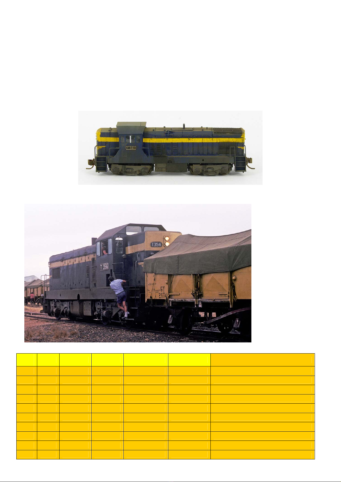
SDLoco3 - Victorian Railways T class diesel-electric Series 2
Blue and Gold era and V/line era.
Requires Bachmann S4 loco, LifeLike or Concor split chassis SW9 to complete, available separately.
Thank you for purchasing this kit and I hope you get many hours of enjoyment from it. Chris Pearce (Spirit Design)
T347 staff exchanger cutouts and no cab valances, circa 1980. Photo courtesy of Mau Bau’s website
Basic history: The T class became the largest diesel class on the Victorian Railways and were built by Clyde’s Granville workshops
over 13 years from 1955-to 1968. As a consequence, there are 5 versions but the group is commonly called by the 3 versions of
“Flat Top”, “High Nose” and “Low Nose”. They were purchased to serve the state’s branch lines and to replace the ageing K’s and
the newly arrived J class steam locos. The 2nd series was constructed from June to December 1959 and when they entered traffic
they were assigned all manner of jobs with other classes.
With the arrival of larger locos in the form of G’s and the aging B class being rejuvenated into the A-class most of the fleet was
scrapped or withdrawn by 1989. For the majority of their life, they were painted Blue & Gold of the Victorian Railways and then,
later on, were painted in the V/Line orange and grey. Towards the end of their working lives, they received the ‘chopped’ valance
treatment which altered their appearance but maintenance was easier. Sadly only a solidary unit no. T356 has made it into
preservation and currently wears the classic VR Blue and Gold paint scheme.
Road Numbers: T347-T356. Model: G8B
CAB
END
Note (P24)
are 2 wooden
1.5mm thick
timber blocks
that are glued
in front of
each cab door
to the
walkway
(P25) are
the clear
windows for
the cab

2
Soldering: Always clean up soldered joints as you progress, as it’s easier in the long run. For an understanding of soldering it
would pay to visit the following sites for information on soldering before attempting your first kit.
http://themodelmakersresource.co.uk/articles/article012.html
http://www.dccconcepts.com/index_files/DCCsoldering1.htm
I’m not the perfect solderer as I also end up with solder runs but I scrape, file and clean the general area so that it doesn’t show as
much. It may take a few minutes on some joints but the end finish on your model is worth it!
It is far easier to use the wire brush pictured below in the Dremel to clean parts just before assembly. Holding the unit at a slight
angle and lightly letting the brush polish the next item to be soldered works very well. It is the simplest method I have found.
Tools needed: variable temperature soldering iron, solder, flux, small files, sanding sticks, fine grade sandpaper 800-1200 grit,
Selley’s Kwik Grip water-based, ‘Duck Bill’ (flat – no teeth) and long nose pliers, ‘Hold ‘N’ Fold’, superglue, Exacto knife, scissor
clamps, weights, soldering aids, Kapton Tape, Blu-Tak, 0.3mm drill bit, pin vice, tweezers, the ‘Wedge’ by Spirit Design for handrail
folding available separately from my website.
Other items: Bachmann S4 loco, Concor SW1200 or LifeLike SW9 for the mechanism, paint, modelling putty to fix up uneven
soldering and weathering powders. These notes cover the Bachmann S4 mechanism only. If you plan to use a LifeLike chassis, a
Spirit Design plywood chassis is available separately. It’s easier than the Y class chassis to put together if you have done this kit in
the past
Assembly Instructions: These instructions may seem long-winded but it’s harder to describe and better for your understanding
than just putting a few pictures in. Some steps require close attention and they are highlighted in bold and italics! Any text in
Green can be done at that point or later on in the construction. Parts referred to in the text are marked (P1), (P2) etc and there is
a coloured picture of the parts to aid you. All brass parts and tabs holding the parts to the etch should be trimmed back and filed
smooth after removal. The main mansard long hood has been performed to aid your construction. Clean parts in the etch with
800-1200 grit sandpaper /emery before soldering a piece into your kit assembly or with a Dremel fitted with a small
conical steel brush - see picture below
More Reference photos:
http://www.victorianrailways.net/motive%20power/t320_346.html http://www.robx1.net/index/index.htm
http://www.pjv101.net/index.htm
Train Hobby T class 2nd series ‘High Cab’ profile book
Assembling the kit:
Walkway:
1. Cut the centre section holding the small parts away from the main walkway etch (P1)
2. Remove the walkway (P1) from the etch brass kit, clean edges and fold the valance sides up at 90degrees using a ‘Hold ‘n’
Fold’ or between 2 bars of hardened ground steel. You may need to take the slight curve out of the brass etch as the brass
is manufactured from a sheet roll. Then ensure the walkway is flat and straight before the next step and solder the inside
edge sides to add strength to the valance and walkway deck. Once soldered straighten and flatten the decks using pliers,
steel blocks or whatever aids you have
3. If you are making the VR blue and gold era loco without the cutaway valances, you will need to fill the dotted line area with
solder from the inside after placing masking tape along the front to stop excess solder leaking through. For the V/Line era
gently remove the dotted area with sharp scissors or scribe through slowly at the rear along the fold line. Not all V/Line
locos had the cutaway valance, see table listed later on for details
4. Bend ends of the walkway (headstock skirts) to 90 degrees
5. Fold a staircase side (P2), then the bottom of step up to meet the side and solder. Repeat for all 4 (P2) staircases
To help keep items straight and to aid you in holding parts build the simple MDF solder board shown later. Make it
whatever size you want but I made mine from 6mm and 3mm MDF boards
Left: Small
conical brush
for polishing
brass etches
as needed.
Right: Drum
sanding unit
for frame
grinding of
locomotive
mechs
VR Blue and
Gold era
walkway
s
h
o
wn h
e
r
e

3
6. At each of the valance ends of the walkway (P1), a small flap should be bent towards the centre of the walkway at about a
45-degree angle. This angle is easy to follow as the flap bend should match the shape in the top of the walkway when
viewed from above
7. Note the side part of the staircase is positioned away from the front/rear skirts of the headstocks on the
walkway. Test fit a staircase (P2) and once satisfied with the fit and squareness, solder it into the walkway making sure
that the tab on the top slots into the hole provided in the walkway. Also, make sure the staircase is square and straight
about the front/rear walkway and the headstock skirts. Solder the lower step edge of the stair casing to the headstock
skirt. Where the tab of the stair casing (P2) comes through the walkway (P1), fill this with solder flush with the walkway.
Solder the opposite side of the staircase to where the valance flap meets the staircase. Repeat for the other 3 staircase
units (P2)
8. Clean up any excess solder on the completed walkway and make sure the centre area is free from any etch holding tabs
9. Make sure that the walkway is straight and flat. If not it can be twisted by using pliers/steel bars to achieve a
flat and square surface. You must achieve this as the entire superstructure relies on this being correct. Take
your time to achieve the end result.
Long Hood:
The long hood (P3) (Mansard sections) has been pre-formed and tack soldered to make construction easier for
you
1. Complete the soldering of the nose to the long hood where the tack soldering has already been applied. If you can’t get a
clean solder to join around the end you can use filler for minor imperfections
2. Using the paper guides as spacers under each section, solder each of the long hood handrails (P4) into the holes provided.
It will be easier if you solder the 3 longer legs of the handrail and then proceed to the others. The paper spacer should be
placed between the handrail and the loco body which creates a gap when soldered the handrails stand proud of the body.
Soldering should be from the inside of the long hood body
3. Using pliers make a 2.5mm handrail using the 0.3mm wire provided and solder into the nose holes. Use a slither of paper
to space the handrail from the body and then clean the body up of excess solder
Short Hood:
1. (P5) Fold the nose sides (but not the front) into a ‘U’ shape and solder inside along the main fold lines. The nose front
panel will be at 90degrees to the sides
2. Using pliers bend the two side sections of the nose slightly down so they match the T class nose shape
3. Using pliers bend the angled nose section down so that the bottom edges of the nose are in line with the bottom edges of
the main nose shaped and formed in step 2. The nose front should sit on the edges but not past the edges of the main
nose sides and then be soldered. If it does not the nose section may need more or less bending to achieve this. In
addition, you may need to push the nose front up towards the roof of the nose body with pliers but take care. When happy
with the overall shape, fill the gaps between the nose and the nose main nose body with solder. Using a file radius the
nose corners and sides to look similar to the real loco
4. Using pliers make a 2.5mm handrail using the 0.3mm wire provided and solder it into the nose holes provided using a
paper spacer between the handrail and body
This edge up
against the
headstock
end of
walkway
VR Blue and
Gold era
walkway
shown here

4
5.
Cab:
1. Fold lines are on the inside of the cab (P6). The main front of the cab has 2 high windows side by side and this goes
towards the short nose. Fold each of the sides 90 degrees and workaround until the 2 high windows of the cab rear meet
squarely in the centre. Butt solder the back 2 high window halves together forming the cab into a box shape. Solder along
the internal fold lines of the cab. Try not to fill the handrail holes in the fold line of the cab, which are just below the
window line. If you do just drill them out slowly with a pin vice
Cab roof:
1. Depending on the era being modelled you can opt to have vigilance bumps on the cab roof (P7) or not. To create them,
whilst the cab is in the etch use a small blunt nail and push the 3 vigilance bubbles on the underside of the cab where the
fold lines are etched. There are 3 trial bumps for you to test your technique in the main etch just next to the cab
2. Bend each side of the cab roof to match the cab formed in the previous steps. Fold lines are on the inside of the roof. Do
not solder the cab roof on as it glued on last after painting and windows have been inserted into the cab
Assembly of the main components to the walkway:
1. Make sure that the staff exchanger recesses in the cab (P6) are pointing towards the small nose end of the walkway; insert
the cab tabs centrally into the slots provided in the walkway. With care solder one side to the walkway whilst keeping it
square and then repeat for the other side. Fill the remaining seams with solder
2. Adjust and twist the long hood shape to be square and true before proceeding to the next step
3. The long hood has two brass tabs that should be bent to approx. 60 degrees. Slide the long hood into the walkway so the
nose middle flat section sits flush with the end of the walkway
4. Note the long hood will sit on top of the walkway when soldered but also inline and flush with the inside etched hole
through the walkway. Using the MDF soldering aid push the upturned walkway with long hood assembly into the corner so
that the tab butts up against the walkway stop and will not go any further. Solder a small section and check that
everything is good
5. Repeat for the other side tab and gradually push the loco body sides to match the cut-out profile of the walkway etch and
solder in place but DO NOT SOLDER the tabs
6. Now that the long hood is solder all around bend the tabs back and forth until they snap cleanly off and discard
7. Repeat a similar procedure for the short end nose (P5) section
8. Place the completed unit on a flat surface and check that the loco is not twisted. Gently straighten if twisted
Checking for squareness before adding the cowcatchers
9. Adjust/trim if necessary after trial fitting the cowcatchers (P8) to the headstocks - the fold line faces to the inside of the
loco and are at the bottom. Use Super Glue Gel for this procedure if your soldering skills are new. With pliers, gently bend
the lower portion at 30 degrees. See prototype photos above or model below
10. Thoroughly clean the loco shell of any excess solder before attempting the handrails as its easier at this stage than later
Adding details:
1. Glue (P9) 3D print exhaust into the ½ etched depression on the long hood matching the exhaust over the hole
Rear of
loco cab

5
2. Using the 20thou wire provided solder or glue it into position on the long hood, on the centre line and just forward of the
radiator exhaust vents, with it protruding 1.0 – 1.25 above the mansard long hood roof
3. Glue or solder 8 lift rings (P10) into the holes provided in the long hood and the nose roof sections
4. Glue the headlights (P11) into the depressions on each of the noses
5. Glue or solder the step treads (P12) onto the holes provided in each staircase and trim the tabs protruding through the
rear
6. Depending on your era cab valances (P13) are glued at each of the corners of the cab where it meets the walkway
7. Depending on your era you may need to fill the depressions in the cab sides representing the staff exchanger holes
8. Horn (P18) should be trimmed to one forward and one aft-facing unit from the 3-trumpet part supplied. Use the smallest
2 units from the set
9. Glue (P24) two small 1.5mm thick wooden blocks in front of each cab door to the walkway
Walkway handrails:
1. Solder the short nose cab front handrails (P14) (6 x 6 mm) to the walkway and cab. There will be a small section left
hanging below the walkway. Trim the excess handrail below the walkway
2. Solder the rear cab handrails (P15) (4 x 6 mm) to the cab and walkway. Make sure they look square and correct
3. Solder the short nose long handrails (P16) (4 x 10 mm) to the walkway paying attention to the orientation of the units
relative to the body as per the prototype. You will find it easier if you solder the nose first and then proceed to solder the
longer arm to the staircase. Note this will necessitate the handrail to be slightly bent to achieve this. See photos of the
model and prototype
4. Solder the “U” shaped handrail (P17) to the walkway and then solder the longer leg to the lower step. Twist handrail to
shape after securing. Repeat for the other side
5. ‘Pre Tin’ the headstock face with solder where the rear large handrail (P18) will attach. ‘Pre tin’ the back of the handrail
where it will attach to the headstock. Clean any lumps from the faces of both units and sweat the handrail into position
6. Glue the 2 plywood steps (P19) outside the door etch at both front and back of the cab against the walkway
My original prototype shows brass/copper exhaust area but is now a 3D part. Note the cab roof is not yet glued on
Fuel Tanks:
1. Glue (P20) into the notch of (P21) Fuel tank/Battery box and repeat for the other side
2. Glue (P22) battery box bottom across between the 2 battery boxes to fill in the space. When dry radius a small amount
with a file on the bottom to form the fuel tank and battery box curve that is a feature of the real unit. Set this aside and
alter slightly depending on which chassis you choose for your loco
Bachmann S4 disassembly and modifications:
Hint: Use a camera or phone to take photos of the disassembly procedure if you don’t feel confident of where all the parts come
from.
3. Remove body by inserting a small screwdriver between the chassis and the side sill and then gently pry the shell upwards.
Once it is raised from the base of the chassis, the shell should pull off readily. There are 4 dimples that grab the inside of
the body. Located 21mm on either side of the long hood and 21mm back from the front of the cab. Insert your
screwdrivers around these areas to free the body
4. Remove the screws securing the two weights above the bogies
5. Remove 2 screws securing the DCC board
6. Unsolder the four wires that are attached to the bogies at the DCC board end. With the tip of a small screwdriver, scratch a
line on one bogie underside face and on the walkway face where it is housed. This will aid the correct bogie going back in
its correct spot although it shouldn’t matter we know this configuration was done at the factory worked well
7. Remove the bogie worm drive covers by gently prizing them off at the long end near the face of the weight towers. Take
your time as this is fiddly
8. Using the photo below as a guide file/grind the Fluro green area with the weight that has two screw holes to the width of
the running board of the chassis
(P17)
(P18)
(P15)
(P14)
(P16)

6
9. Trim the weight to match the profile just created in step 8
10. Grind off the battery box faces flush with the walkway sides
11. Grind away the area on the chassis walkway side edges so that slides into the body freely
12. At each corner of the Bachmann chassis, running board remove a 2mm x 2mm section as per the photo below
Bogies:
1. Trim the brake block shoes and clasp extensions flush with the bogie side frames
2. Using a small screwdriver and at one end of the bogie insert it and gently twist so that the bogie frame separates from the
bogie mechanism. Note the orientation of the wheels and gears are before total removal
3. File the bogie sides down so that the raised detail is flat with the background main shape
4. Trim the excess flash from each of the T class cast bogie side frames and glue these to the face of the bogie side frame.
See the photo below of the model or prototype pictures to gauge placement
Chassis Mechanism re-assembly:
1. Using any notes or phone /camera shots, reassemble the chassis with bogies, grease the gears and install the DCC decoder
board. Resolder the bogie wires to the board
2. Glue (P23) wooden walkway to the top of the Bachmann chassis so that the cab end is placed over the original cab end of
the chassis. I.e. the area where the weight with the 2 screws was originally
3. Adapt or trim the light from the DCC board as it will foul the body at its normal height
4. Glue the battery box/fuel tank to the chassis so the battery boxes are facing the cab end
5. Glue the 2 wooden coupler spacers to the underside of the chassis in front of the bogie towers
After 12 months my original Bachmann DCC board died so I replaced it with DigiTrax DZ126
Painting:
The brass body: The whole etch needs to be cleaned before priming and final colour application. All excess solder should be
minimised. There are several ways of cleaning brass but to bathe the brass in warmed Vinegar for 20 minutes is recommended,
then wash with fresh water and then air dry before applying an etch primer. Some people skip the priming stage if they are using
water-based acrylics or use a sandblaster.
VR Blue and Gold era: - Steam Era diesel blue: Cab roof, loco shell and exhaust stack depending on the era. Black:
Underframe, bogies, air tanks, handrails and associated gear. Silver: Exhaust stack depending on the era, fuel sight gauges,
windscreen wipers, central side window pillar and horns depending on the era. Red: Horn trumpet ends depending on the era.
Steam Era diesel yellow: handrails depending on the era, nose face and the long hood face ends as per prototype photos
V/Line Orange and Grey era: - Steam era V/Line Orange: valance sides, nose faces and nose handrails, cab sides only and
headstocks/pilots. Steam Era V/line Diesel Grey: All other areas except staircases. Black: staircases, fuel tanks and bogies.
Silver: exhaust and middle bar of the cab window. White: all walkway handrails only
Numberplates and number boards in lights: Depending on your era the numberplate background will be either diesel blue or
black, which is the most common. If painting a blue background polish the plate first before coating. Once the paint is applied
carefully, wipe away the paint on the raised numbers, class letter and border. For black numberplates, repeat the steps above.
Then lightly paint a round toothpick in a small section with white paint and then gently roll this across the raised sections of the
numberplates to paint the detail.
The paper number plates are best trimmed as close as possible to their respective white edges and applied to the loco using
Microscale clear water-based topcoats as this acts as a glue as well as allowing you to put a water-based topcoat over an existing
enamel or water-based VR Royal Blue
Decals:
The Blue and Gold era chevrons and stripes are the highest quality decals on the market and have been especially screen printed for
Spirit Design to match Steam Era Diesel Yellow. They also feature a unique border fractionally wider than the artwork work. This
means you can cut away from the decal and when soaking off, only the artwork with the small clear border will come away. No
New Cab end
Original
Bachmann cab
end weight now
becomes the long
hood end
7
more having to trim as close as possible as the special mask does this for you. V/Line era: using photos as a guide place the decals
as per the prototype on the sides and noses of the loco
Final assembly:
Glazing:
Where there is a score line on each window section, bend this down 90 degrees from the scoreline. Do a test fit into the cab of each
window set (P25) and trim where necessary as the design allows for a snug fit. Using a couple of small dabs of water-based Kwik
Grip apply below where a window opening is to attach the windows
Roof: Using water-based Selley’s Kwik Grip apply a bead of glue around the top edge of the cab and then centre the cab roof into
position making sure the etch line and rivets are pointing towards the long hood. Use photos as a guide.
Couplers:
1. Test fit the chassis into the body and open out the coupler access in the pilot enough so that the coupler can be pushed
from the front into its final position on the loco
2. Drill 0.8mm holes for the coupler screws and attach the couplers which will then lock the body to the mechanism
My completed and weathered model with cab valances is ready for Wallan using a Bachmann S4 mechanism
Prototype reference photos:
T356 shunting
Photo Courtesy of
Geoff Winkler
Road
# Serial# Inservice Withdrawn Disposition Colourschemes NotescourtesyofMarkBau’swebsite
T347 59‐205 22/06/1959 Mar‐88 scrapped vrb
T348 59‐206 15/07/1959 Jun‐88 scrapped vrb 645Eengine,early80's
T349 59‐207 1/08/1959 Aug‐88 scrapped vrb
T350 59‐208 24/08/1959 May‐89 scrapped vrb‐vlo choppedvalance,beclawatwindows
T351 59‐209 14/09/1959 Sep‐89 scrapped vrb‐vlo choppedvalance
T352 59‐210 28/09/1959 Jun‐89 scrapped vrb‐vlo choppedvalance
T353 59‐211 19/10/1959 May‐89 scrapped vrb‐vlo choppedvalance,beclawatwindows
T354 59‐212 9/11/1959 Oct‐88 scrapped vrb‐vlo choppedvalance
T355 59‐213 30/11/1959 Jun‐88 scrapped vrb
T356 59‐214 14/12/1959 Dec‐88 toSteamrail vrb

8
Simple solder board made from 6mm and 3mm MDF 100mm wide x 150mm long. Use whatever measurements or scraps you have
available
T351 chopped valance Geelong loco 29/04/1989. Photo Chris Pearce
T 353 between duties at Geelong 04/03/1989. Note the different chopped valance compared to T351. Photo Chris Pearce
Other SPIRIT DESIGN Toy manuals

Popular Toy manuals by other brands

VQ Model
VQ Model Trojan T-28 instruction manual

Seagull Models
Seagull Models ERCOUPE Assembly manual

Faller
Faller 222597 manual

PARKZONE
PARKZONE Spitfire Mk IX instruction manual

K&W Model Airplanes
K&W Model Airplanes Fokker E-III Assembly manual

Fisher-Price
Fisher-Price HEAD SPINNERTAIL W1392 user manual


Team Losi
Team Losi LOSB0105 user manual

Titan Dynamics
Titan Dynamics Hawk user manual

marklin
marklin 39562 instruction manual

THUNDER TIGER
THUNDER TIGER AH-1W Super Cobra Gunship mini Titan E325 CONVERSION... Assembly Manual & Parts Catalogue

marklin
marklin BR 260 manual

Eduard
Eduard Zimmerit Panther Ausf.G manual