K & W Model Airplanes Inc.
partofthe fuselage.Wiresareledfrom theservo
arm straight down to the arms of the wing
warping actuator. Stretch the wires and lock.
Theremaining servos are installed in the
servo tray and note that the tray is inverted!
Nextistheservofor the throttle. Connect
the wire arm to the servo and through the fire
walltothearmonthetrottlewithaballlink.Make
sure that is working freely.
Elevator servo is connected to the joy
stick, also with a ball link on the joy stick.
Rudder servo is connected in the same
fashion to the rudder bar.
Theupper tray contains the receiver and
the battery pack. The switch can be mounted
onthedash board orehidden under the cowlon
the upper tray and actuated by a push-rod
protrudingintothecockpit.
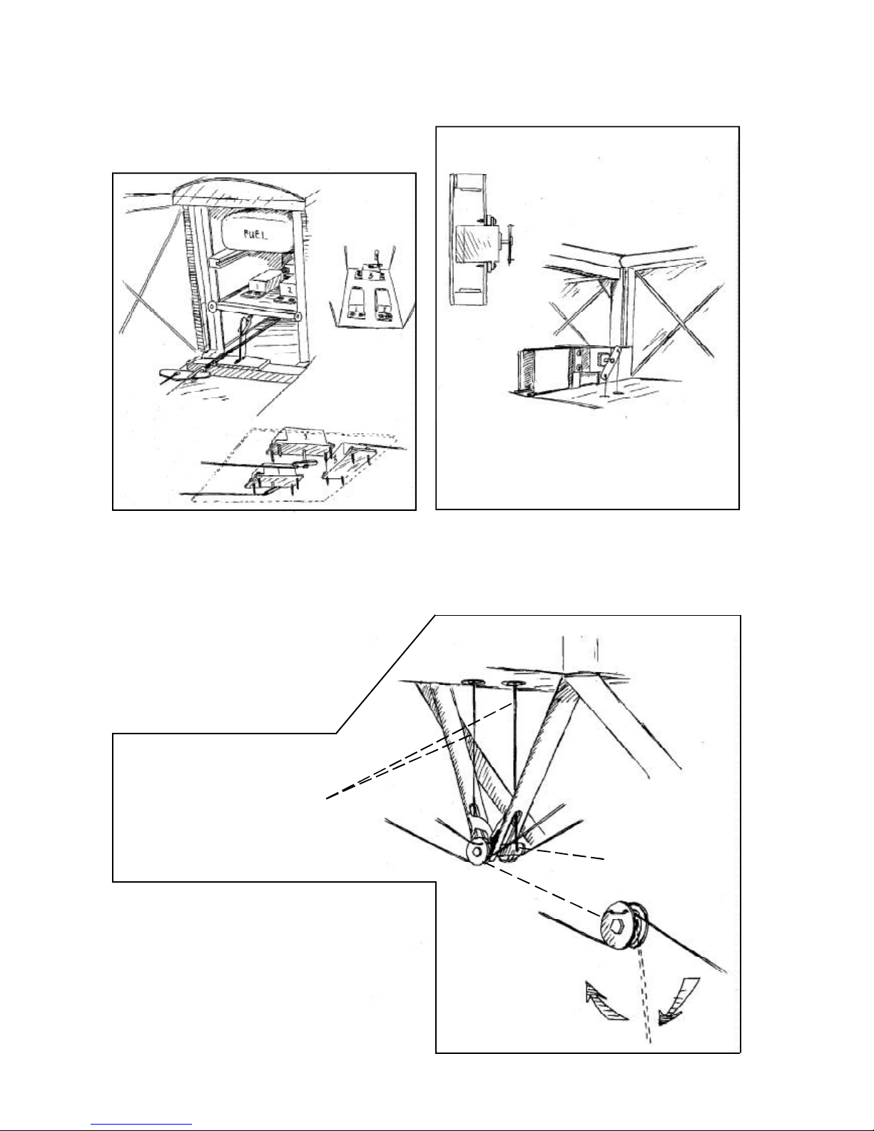
Installation of engine.
The engine mounts have been installed in
a unusual fashion for several reasons.
Theneedfor adequate cooling. Theaccess
totheglowplugwithouthoeinthecowlandfinally
togetthe carburator in linewith the center ofthe
tank.1.Removethe engine mountsanddrill and
taptheholesfor the engine. Placetheengineas
close to the fire wall as possible. If you have to
relocate the engine mounts, you can do so and
theblind nuts are not securedwith glue. Should
you desire to install a 4-stroke engine you may
have to make an opening in the firewall for the
carburator and a small "box" so that no fuel
spreadsintothe fuselage. On thefullsizeplane,
the carburator is located between the two air
intake tubes!
2. Drill the holes from the tank to the
carburator, preassure tap and the filling cap.
3.Installtheengineandconnectthethrottle
servo.
4. Make cut outs in the dummy engine so
that this will fit in front of your engine. You may
haveto remove 1 complete cylinder to allow for
the cooling air to pass the engine head. This
"surgery" isexecuted by removing a little at the
timeand checking. Whenyou are satisfied with
the fit and openings, screw the dummy engine
ontothe engine mounts using 3 mm screwsand
washers.
5. Reinstall the engine cowl using 3 #2
sheet metal screws.
Installation of servos, tank, battery and
receiver.
The aileron servo is installed in the lower
partof the fuselage
The trottle servo and the rudder servo
are installed in the servo tray. The tank is
positioned at the side of these servos.
The elevator servo is is installed inverted
inthe tray.
Battry pack and receiver are positioned
intheuppertray.
The switch ismounted on the dash board.
1. Attach a ball link head to joystick and
rudder bar in the appropriate holes. You may
havetoenlargethe holes to takethescrewfrom
the ball link (Dubro #189 set of 2).
2.Installtheservosfor rudder and elevator
and temporarily connect the servo arms to the
ball links. Deflection for elevator is 20° up and
downand for rudder30° right and left..
3. Install and connect the throttle servo in
thefashionyouprefer.
4. Install the tank in the available space in
front of the rudder and throttle servos..
5.Installtheaileronservoin the lower wing
usingservo tape. The servo arm attaches tothe
Kwick-link allready installed on the aileron
connectionrod. Deflectionshouldbe20° upand
down.
6. Fasten the upper servo tray and make
the final connections.
7.Installtheradioswitchonthedashboard.
8. Place the receiver and the battery pack
in the upper tray, wrapped in foam rubber and
secure with rubber bands.
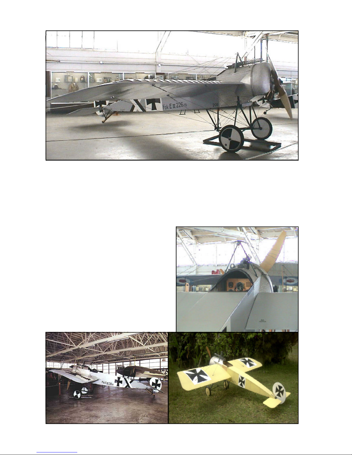
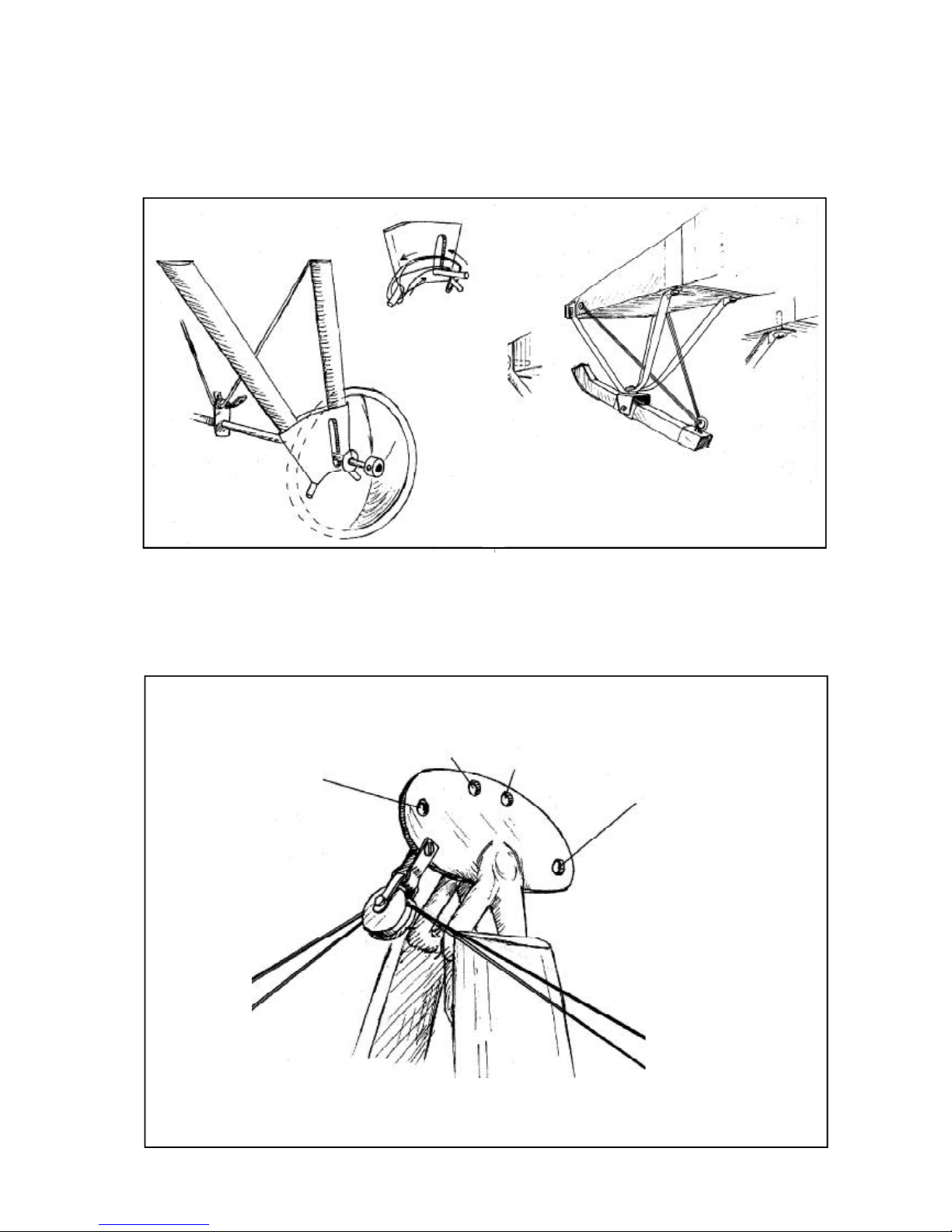
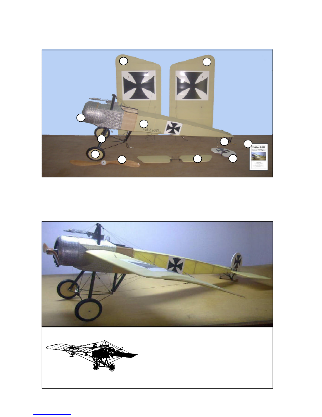
Assembly of the Fokker E III
All parts have been assembled at the
factoryand onlydisassembledfortransportation.
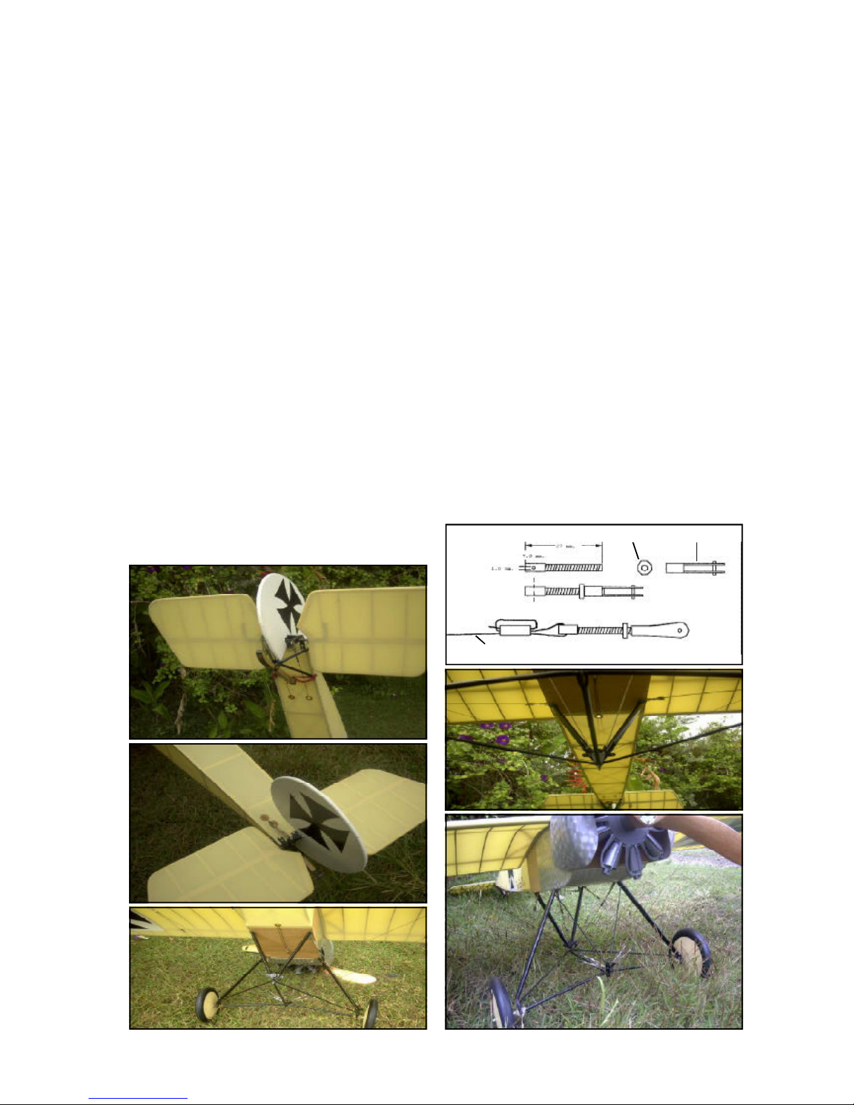
Rudder and elevator wires are factory
adjusted but may need some tensioning
adjustmentafter a while.
1. Fasten the elevator to the fuselage with
4screwssupplied. Slide the upperelevatorwires
through the holes in the fuselage and attach to
theupper elevator horns.
2. Install the rudder assy by inserting the
music wire the hole in the rudder and secure
with a stopper screw in the tail skid assy.
3. Attach the lower elevator wires and the
rudder wires. The upper set of wires are for the
rudder.Check theaction ofelevator andrudder.
The elevator is actuated with the joy-stick and
the rudder with the rudder bar.