SPIRIT DESIGN SDLocoY1 User manual

ABN 92 510 718 068
Web site:
http://www.spiritdesign.com.au
SDLocoY1 - Victorian Railways Y class diesel-electric.
Requires LifeLike SW9/1200 loco to complete, available separately.
Thank you for purchasing this kit and I hope you get many hours of enjoyment from it. Chris Pearce (Spirit Design)
Brand new Y101 arrives from Clyde and is seen outside Dynon. Victorian Railways photo
Basic history: The Y class was the second-largest diesel class of the Victorian Railways with 75 members being built by Clyde’s
Granville workshops in 3 batches between 1963-1968. Utilising bogies off scrapped swing door electric trains and featuring a 6-
cylinder EMD 567 and later a 645 engine they were highly regarded by crews and were a versatile go-anywhere engine. The long
hood is designated the no1 end and controls were arranged accordingly. The fleet was seen over the entire VR system with 4 always
on the standard gauge. Later on, in life, they received the V/line orange and grey livery and this was later replaced on the
remaining active units with the new V/line red and blue. Some were fitted with DOO window openings altering their appearance. A
few have made their way into private tourist railways and are still giving reliable service.
Soldering: Always clean up soldered joints as you progress, as it’s easier in the long run. For an understanding of soldering it
would pay to visit the following sites for information on soldering before attempting your first kit.
http://themodelmakersresource.co.uk/articles/article012.html
http://www.dccconcepts.com/index_files/DCCsoldering1.htm
Tools needed: small files, sanding sticks, fine grade sandpaper, fast-drying wood glue, Selley’s Kwik Grip hydrocarbon-based,
‘Duck Bill’ (flat – no teeth) and long nose pliers, Plyobond or superglue, soldering iron, solder, flux, Exacto knife, scissor clamps,
weights, soldering aids, Blu-Tak, 0.3mm drill bit, pin vice, tweezers.
Other items: decoder wire, 2B pencil, paint, couplers, LifeLike SW9/1200 loco for motor, bogies, weights and phosphorous bronze
pickups etc
Assembly Instructions: Some steps require close attention and they are highlighted in bold and italics! Parts referred to in the
text are marked (P1), (P2) etc. All brass parts and their holding tabs should be trimmed and filed after removing from the etch.
Reference photos: http://www.victorianrailways.net/motive%20power/ydie/ydie.html
http://www.robx1.net/index/index.htm
http://www.pjv101.net/index.htm
Train Hobby Y class profile book
Walkway:
1. Cut the centre section holding the small parts away from the walkway etch (P1)
2. Remove the walkway (P1) from the etch and fold sides up to 90degrees using a ‘Hold ‘n’ Fold’ or between 2 bars of
hardened ground steel
3. Bend ends of the walkway (headstock skirts) to 90 degrees.
4. Fold a staircase side (P2), then the bottom of the step up to meet the side and solder. Do this for all 4 (P2) staircases
5. Tests fit a staircase (P2) and once satisfied with the fit, solder it into the floor making sure that the tab in the top slots into
the hole provided in the walkway. Also, make sure the staircase is square and straight with the front/rear walkway and the
headstock skirts. Then solder the edge of the stair casing to the walkway skirt. Repeat for the other 3 staircases (P2).
Note the side part of the case is positioned away from the front/rear skirt of the walkway
6. Where the stair casing (P2) comes through the walkway (P1), cover this area over with solder and file the tab to make the
walkway decking flush
7. Clean up any excess solder on the completed walkway and make sure the centre area is free from etching holding tabs and
set aside once the entire walkway is flat and straight when sitting on a flat surface
8. Make sure that the walkway is straight and flat and if twisted use pliers/steel bars to achieve a perfectly flat
surface. See the walkway picture below
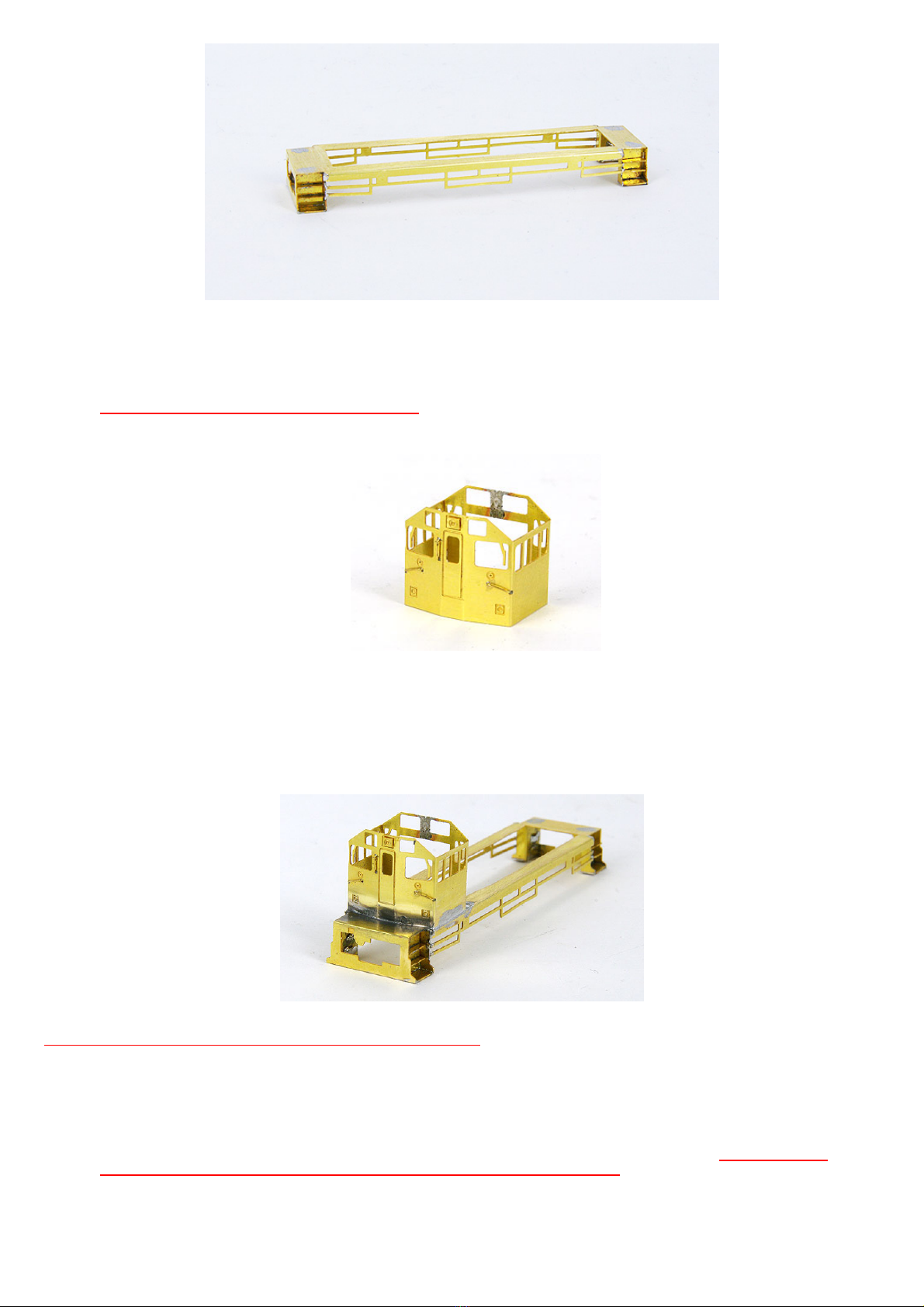
Cab:
1. Whilst the cab etch (P4) is still flat fit a 3.0mm cab door handrail into the holes provided. Insert a small bit of paper
(photocopy paper thickness is ideal) between the handrail and the cab so that when soldered there will be a space beneath
the handrail after the paper is withdrawn when the soldering is done. If you need to open the holes up use a 0.3mm or
no79-80 drill
2. Using long-nose pliers bend the cab front (P4) into the familiar shape of the ‘Y’ class. Only a small amount is needed.
Fold lines are marked on the inside of the cab
3. Fold the remaining sides until the back of the cab meets and aligns and solder. View from above and push/pull the cab into
shape and looks as it should for a Y class
4. Test fit the cab onto the walkway and then tin the area where the cab will sit on the walkway (P1) and also the bottom
edges of the cab (P4) itself
5. Test fit the cab (P4) so that its edge is in line with the same shape that is in the walkway (P1) near the steps. When
happy that the cab is central and conforms to the shape of the walkway, solder one edge near the front and then check for
alignment again. If all is well solder the remaining sides of the cab to the floor
6. Fit 3.5mm handrails for the remaining 2 cab handrails into the holes provided. If you need to open the holes up use a
0.3mm or no79-80 drill to clear away excess solder
7. Glue a loco headlight (P5) into the square above the front door window
Cab roof:
Note -The large fold lines are on the underside of the cab roof.
1. Insert 2 lift rings (P23) into the holes provided on top of the roof (P7) and solder/glue from underneath. Enlarge the
holes if necessary carefully with no 78-drill bit or a 0.3mm drill bit. Trim the excess length of lift rings below the roofline
once soldered. It may be easier to spot the holes by looking at the underside of the cab roof
2. Fold the cab roof (P7) to the cab profile and set it aside. This is glued in place after painting during the final assembly
Long Hood:
1. Run a small bead of solder along the fold line of the nose where it meets the long hood roof (P8). This is a safety
precaution so that you don’t accidentally break it off during the next steps
2. Make 2 x 2mm handrails that will fit into the long hood (P8) roof near the rear grill. They run across the long hood. Again
use paper to space and solder the handrails into place and enlarge the holes if necessary carefully with no 78-drill bit or a
0.3mm drill bit
3. Fit and solder the long hood handrails (P9) into the holes provided along the side of the long hood. Use a paper spacer to
make the handrails stand proud of the long hood sides
4. Fit the fuel gauges (P10, P11) etches into the holes provided just behind the cab. Use prototype photos depending on
which class number you have chosen as they vary between the earlier series and the later ones. There are 2 spares
provided. If building a Y class within the range of Y101-Y125 swap the positions of the gauges shown in the photo below so
that the battery box will fit on the walkway
5. Join the 2 exhaust stack base plates together (P12) so the holes align and fit the long hood roof so the large hole faces
towards the rear of the long hood inside the etched lines
6. Join the roof water tank plates (long end) together (P13) and fit them onto the space provided at the long end making
sure that the 3 holes are closest to the end of the long hood
7. Join the roof fuel tank top plates (cab end) together (P14) and fit them onto the area provide making sure that the two
holes with the larger spacing between them are towards the cab end
8. Turn the etch over onto some foam/cloth for protection and clean the underside of any solder/dags
9. With a rat tail file clean some of the solder out of the rear nose fold line done in step 1 and bend the long hood (P8) rear
end nose section into a similar shape of the cab front utilising the fold lines provided in the back of the etch using long nose
pliers
10. Using your hands, fold up the sides of the long hood. Don’t worry about the section near the cab not matching the profile
as yet
11. Bend the rear long hood nose up to meet the sides of the long hood and pay attention so that the bottom edge
meets the side’s bottom edges as well. This may take a few pushes and tweaks with the pliers to achieve this. Once
satisfied, solder one edge bottom edge to the rear edge wall’s bottom edge. If happy with the fit, continue with the other
side of the end rear wall. Note the vertical edges of the nose are on the outside of the long hood
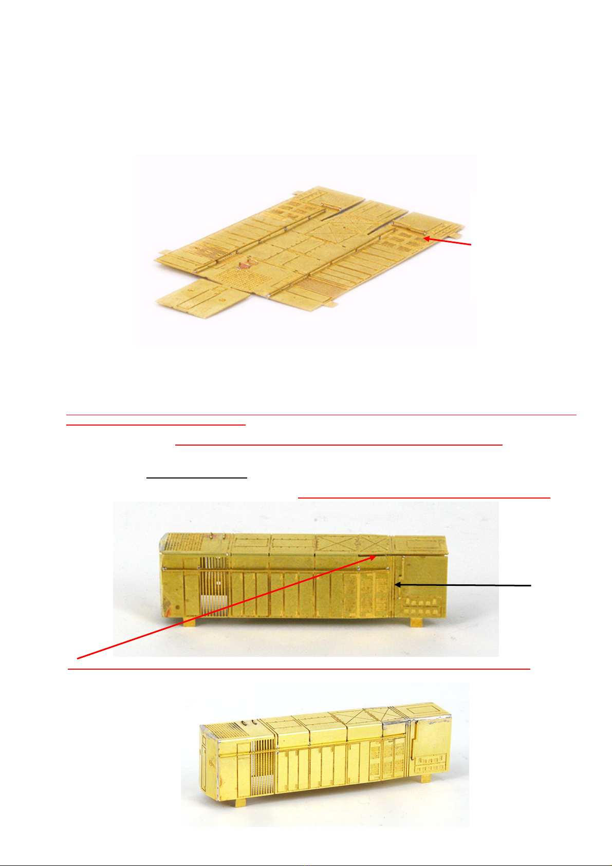
12. Using ‘Flat jaw’ pliers bend the section of the long end to match the roof shape. Using ‘long nose’ pliers bend the 3-panel
line section (see the black line below) in line with the long end roof profile. Use pliers to bend the last section to match the
rest of the profile. See note below in red. When happy solder the tapered sections first followed by the small panel line
section and finally the last remaining section. Make sure the long hood nose is in line with the rest of the unit and if not
touch up with a file to make a straight and flat surface. Be careful not to fill the roof radiator grille with solder
Note the gap here. Fill this with solder – don’t force it down and solder, as this will cause a slope in the long
end. See photo below of completed joint. Use body filler if you are not confident of filling it with solder
Fuel sight
glasses as for
Y126 – 175.
Note - Swap
the positions
for Y101-125

13. Slide the long hood assembly (P8) into the walkway (P1) until the tabs stop any further movement and bend the tabs up
90 degrees, as this will aid the soldering process. Note the profile of the long hood should match the orientation on the
floor. With care solder around the end and sides but make sure they flush with the walkway edge but NOT above or
below where they meet. Do not solder the tabs themselves as they are broken off once you finish soldering around the
long hood. They are only there to help set up the soldering process. You may have to push the long end (P8) around to
achieve this and use clamps or homemade spacers you deem necessary until soldering is complete.
14. If you are building a Y class in the number range of Y101-Y125 then you need to fold up the battery box cover
(P6) and solder it directly onto the walkway (P1) and up against the cab (P4) on the driver's side after trial fitting first
and filing to meet the shape you have made the long hood
15. Solder (P20) headstock skirts to both the front and rear of the walkway paying attention to the fit of the components. The
smaller chamfered edge goes up against the walkway underbody and the fold lines face into the loco
16. Bend the lower section of the skirts (P20) in towards the loco about 1-1.5mm from the vertical and solder
17. Turn the etch over onto some foam/cloth for protection and clean the underside of any solder/dags paying particular
attention to the area inside the long hood (P8) where it joins the walkway (P1), the cab area (P4), and the area behind
the stair casing (P2) and headstock (P20).
Final Details
1. Solder cab rear fireman’s side handrail (P17) to walkway and cab
2. Solder rear handrails (P18) to the walkway near the rear stair casing. See photo below
3. Fit a plywood step (P15) on the floor of the walkway behind the rear cab door
4. Fit a plywood step (P15) on the floor of the walkway in front of the cab front door
5. Glue lift rings (P23) into the 3 holes provided on the long end roof and shown below in the diagram
6. Glue the long hood rear wall light (P5) onto the square provided
7. In the first hole (P14) behind the cab bend a small piece of 0.3mm brass wire into a loose ¼ circle and glue this into the
hole provided and attach it to the back of the cab centrally near the top. In the 3rd and 4th holes make a very small handrail
2.5mm from 0.3mm brass wire and glue it into place. (See close-up photos below)
8. Glue the plastic exhaust (P19) into the hole provided in (P12). (See close-up photos below)
9. Trim the brass pin supplied to just over 1mm in length and glue it into the larger hole of the water tank plates (P13). See
close-up photos below)
10. Glue the plastic horn (P24) into the remaining hole on the driver’s side at the top of the long hood (P8) so that the single
horn is pointing towards the cab. Enlarge the hole if need be using a no.76 or 0.5mm drill bit and remove one leg of the
plastic horn. An alternative is to drill another 0.5mm hole perpendicular to the original where it crosses the diagonal line in
ten long hood roof plates. (See close-up photos above)
11. Solder the front handrails (P21) to the cab end ensuing an even spacing on either side of the walkway front edge. The
numberplate lugs protruding down should be just over the edge of the walkway allowing it to be soldered as well to the
walkway. Use Blu-tack as an aid if need be
12. Solder the rear handrails (P22) to the rear headstock again paying attention to the spacing
13. There are 8 stair treads (P3) that need to be glued into each of the slots of the staircase units (P2). Start with the top
steps first. After fitting, trim/file off the rear of the stair tread flush with the stair casing
2 views of the completed etched components with details – Y101-Y125
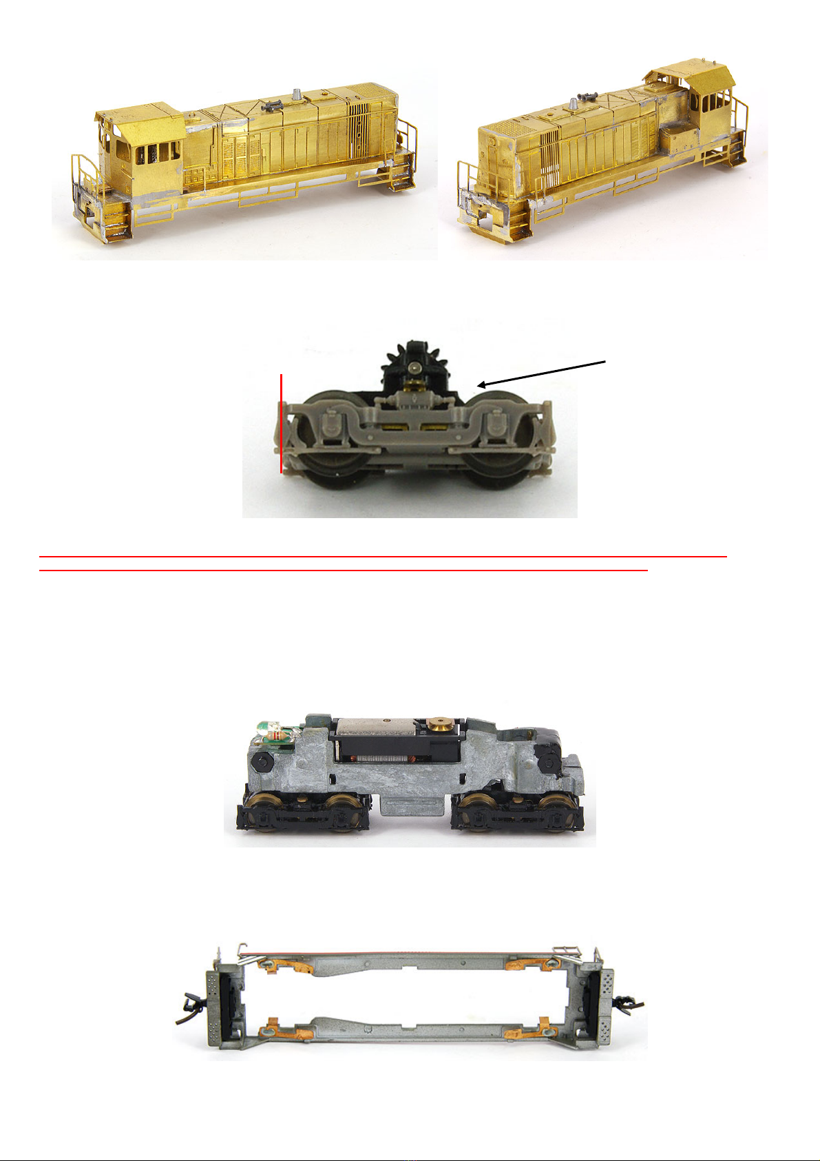
Bogies:
At each staircase (P2) where the bogie swings, slightly trim the brake block area marked by the red line in the diagram below.
LifeLike disassembly:
Make sure when disassembling the mechanism to identify the flywheel end bogie and worm gear to them mark
accordingly (white dot – Tippex) as these bogies must be installed back into the same worm gear.
1. Start by removing the fuel tank
2. Then each of the bogies can be removed by turning them 90 degrees and then gently pulled out. Be careful not to bend the
pickups as they are attached to the body
3. Remove the cab shell after unplugging the centre handrails from the cab. The cab weight will be used later
4. Pushing down on the exposed mechanism whilst holding the walkway, gradually slide the mechanism out of the plastic shell
being careful not to damage the phosphor bronze pickups
LifeLike mechanism with the shell removed
5. Remove the long hood from the walkway and dispose of it. The walkway will be used later
6. Pull the light board free and then ease the plastic caps off that cover the screws and then extract the screws allowing the
body to split in half
7. Pull the plastic cradle off the motor and it is ready to modify
LifeLike Mech pickup tabs that are needed in the new chassis
Nested gear
end of bogie.
Air tank end
Stair case end
Smooth gear
cover end

Motor adaptation
To make use of the motor from the Lifelike SW 9/1200 mech we needed to re-arrange the worms and flywheel on the shafts, which
can only be done with a gear/wheel puller and small press. For future reference, the top of the motor is where the outer silver
casing has a small hole in it. Please mark it accordingly. The flywheel is placed in the long hood end of the chassis when completed.
When the motor has been re-arranged the worm gears should be sitting centrally over the bogies
Original motor
The altered motor fitted with a brass nut as a dampener
The following steps require the use of a gear puller and press to complete
Spirit Design offers a gear pulling service for those that are not equipped to do so for a small fee.
1. Extract the cab end worm gear and set it aside
2. Slide brass nut (harmonic dampener) onto the cab end motor shaft
3. Push the cab end worm gear forward so that the end is about 3mm from the motor casing
4. Extract the long hood worm gear and set it aside
5. Extract the brass flywheel from the motor shaft
6. Press the long hood worm gear so that its end is 3mm away from the motor casing
7. Press the flywheel onto the motor shaft about 1mm away long hood worm gear
This completes the motor adaptation and it can be set aside until the chassis construction is almost complete. If you get a slight
imbalance in the motor when testing you may need to counter the rotational forces of the flywheel by adding a small brass nut
drilled out to 1.5mm so that it slides around on the motor shaft as pictured in the “Altered” LifeLike motor photo above
Plywood chassis: Note the single hole and scribed line at one end of the chassis deck is the reference mark for the cab
end1. Glue the plywood chassis top deck (P38) 0.4mmm plywood to the top of (P25) 1.2mm plywood so that the scribed line
across a small hole is at the same end as each other
2. Glue (P41) to the chassis cab end top paying close attention so that the shape and holes of the bogie are even and
aligned. The notched area goes towards the motor hole in the centre of the chassis cutaway
3. Glue (P42) to the chassis opposite end top paying close attention so that the shape and holes of the bogie are even and
aligned. The notched area goes towards the motor hole in the centre of the chassis cutaway
4. Glue the motor fork marked ‘C’ (narrow) (P26) into the cab end of the motor cut out hole paying very careful attention so
that it sits square and vertical with the chassis floor. The scribed line points away from the motor and to the
headstock end
5. Repeat the same procedure for the wide motor mounting fork (P27) that is for the long hood again making sure that the
scribed line points away from the motor and to the other headstock end
6. Run beads of glue in front of the forks where they join the chassis for extra strength but do not let it encroach into the
bogie mounting slots. Where the forks are glued into the chassis, this is now known as the ‘Chassis Top’
7. Gently clean the holes where the bogies go with an ‘Oval’ file but don’t remove too much as we don’t want the bogies to fall
out. Check for fit with a bogie and ensure they swivel freely. Use a 2B pencil or softer to coat the bogie holes with graphite
to make a slippery surface for the bogies to spin freely
8. Open up the 4 screw holes in the chassis deck near the motor opening with a 34 thou/0.8mm drill (no 65) bit
9. Once dry lightly sand the chassis bottom so that the motor forks are flat with the chassis base
10. Insert the bogies and depending on the play between the hooks that hold the bogie in and the chassis top plate you made
need to use the styrene buffing plates (P39-P40). I have noticed that some of the bogies for the LifeLike are about
10thou difference in height where they protrude through the holes in the deck and as a consequence you may need to use
the styrene buffing plates (P39 & P40) If they are not needed proceed to STEP 13
11. With a sanding stick file away the small meniscus on the 10thou styrene bogie friction plates (P39 & P40) both front and
back which are caused by the lasering process
12. Using Selley’s hydrocarbon Kwik Grip coat the chassis area in front of the motor mounting forks to the edge of the chassis.
Wait 20 seconds and then press the styrene friction pads (P39 & P40) to the chassis top. Once the glue is dry ensure the
bogie holes are clean by inserting a bogie and rotating it around. If the depth of the chassis is too tight once the bogies are
inserted, gently sand a small bit at a time of the chassis bottom until a free fit but NOT a sloppy fit is obtained. It is crucial
to have a neat fit but not a sloppy fit, as this will introduce unwanted harmonics when the motor is running. With a pencil
mark the cab end with a dot using the underside as a guide
13. Glue both (P43) into the square holes (P30) which forms the decoder/chassis locking plate
14. Paint the chassis parts black (P25 & P38)
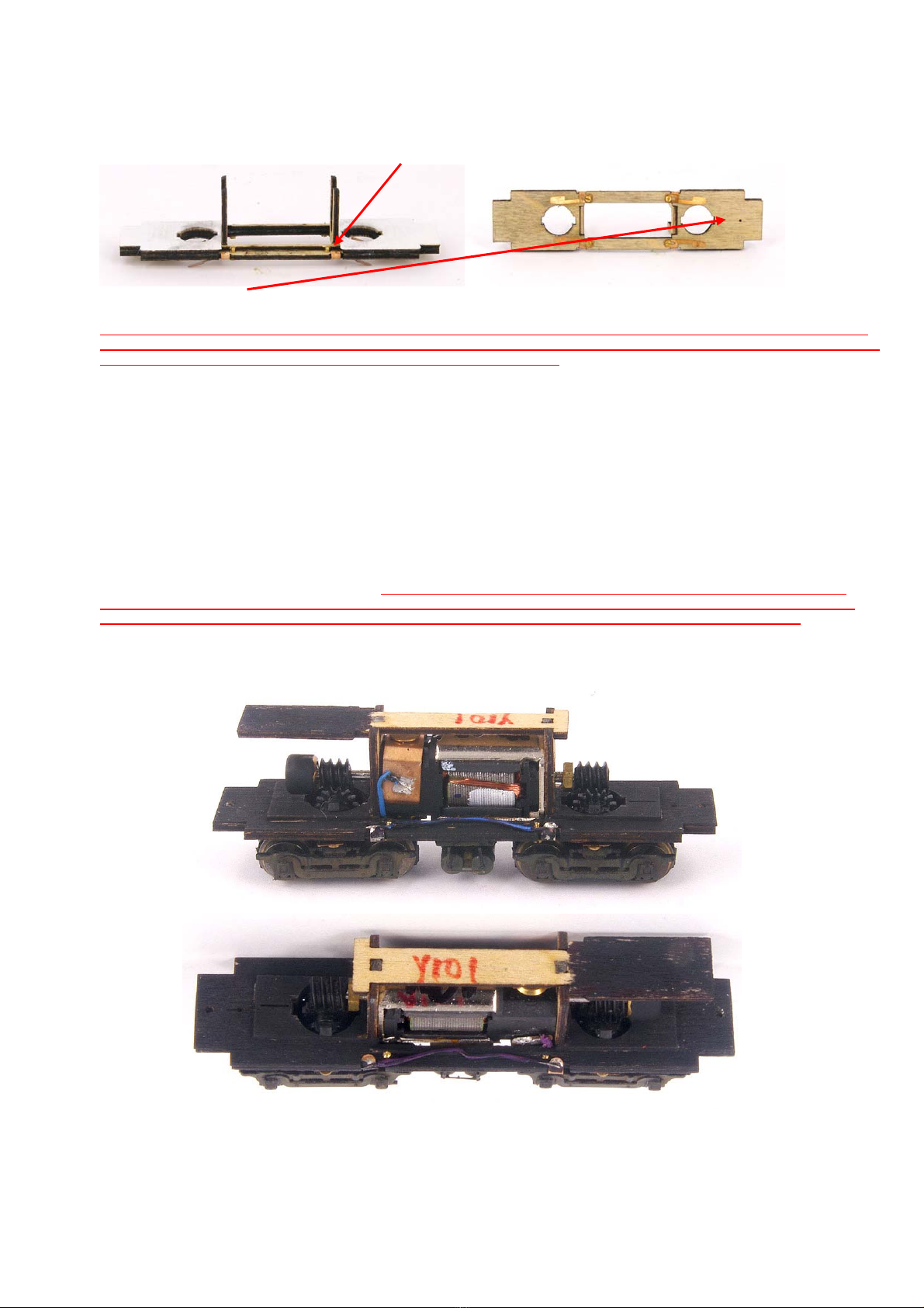
Wiring:
1. Utilising the LifeLike walkway CAREFULLY remove a phosphor bronze pickup
2. Lay a scrap piece of the chassis floor over the donor phosphor bronze pickup (P33) and bend the small arm back over the
scrap piece forming a little “U” shape. Repeat for the other 3 pickups
3. Attach the pickups using the four 14BA screws supplied to the underside of the chassis deck and bend the vertical tabs over
so that they form a soldering point for the motor. See photo
Cab end designator(older chassis shown here but the new chassis has the same process)
4. Note these instructions apply to wiring the chassis for DC operation only. Should a DCC decoder be desired to
be fitted the manufacturer’s instructions are to be adhered to. The holes in the locking plate (P27) are to allow
you to feed decoder wire along and also allow for wiring of lights. Using decoder wire run a length of 27mm
between the two pickups on each side so that they are linked electrically together. Use red on RHS (driver’s side) and black
on the fireman’s side using the parts list diagram. (DC wiring)
5. Solder 18mm (long phosphor bronze tab) and 12mm (short phosphor bronze tab) decoder wire to the pickups near the
screw head and then feed the wires back up in the two narrow slots provided in the base (long hood end) (Note DCC wiring)
6. Position the motor into the cradle with the flywheel at the long hood end and ensure the motor orientation is correct with a
hole in the motor casing to the top. Push the motor down into the cradle until snaps into the forks paying attention so that
the decoder wires sit in the rear slots provided in the chassis
7. Solder the 18mm decoder wire to the long phosphor bronze tab
8. Solder the 12mm decoder wire to the long phosphor bronze tab
9. Make sure the pickups are at about 30 degrees
10. Glue (P36) coupler spacers at each end of the chassis so that the holes and orientation of the unit matches the chassis
profile holes
11. Insert each bogie in and rotate 90 degrees. Note as you turn the bogie a wheel will catch a pickup. Don’t keep
turning until you use a small screwdriver to hold the wiper down as you continue to rotate the bogie into its
correct alignment. Beware at times until you have finished construction that this may happen again
12. Test run the chassis and if necessary fit the motor locking plate assembly into the top of the forks above the motor as this
will squeeze the motor hard up into the chassis. If the chassis stalls or jumps a bit up and down, adjust the angle on the
pickup tabs and fine-tune as necessary. Remember to grease/oil the chassis as per normal practice
DC version of the completed chassis with a motor locking plate, air tanks after testing and oiling
Air Tanks:
1. Trim the two smaller rectangles attached to (P31) and glue them across the narrow ends in line with the edge
2. Cut the remaining tag so that (P32) becomes two pieces and glue these into the holes on the opposite side of (P31), i.e
not the face that has the two smaller bits from step 1
3. Glue (P33) face to face
4. Pull the original air tanks off the side of the LifeLike loco mech fuel tank
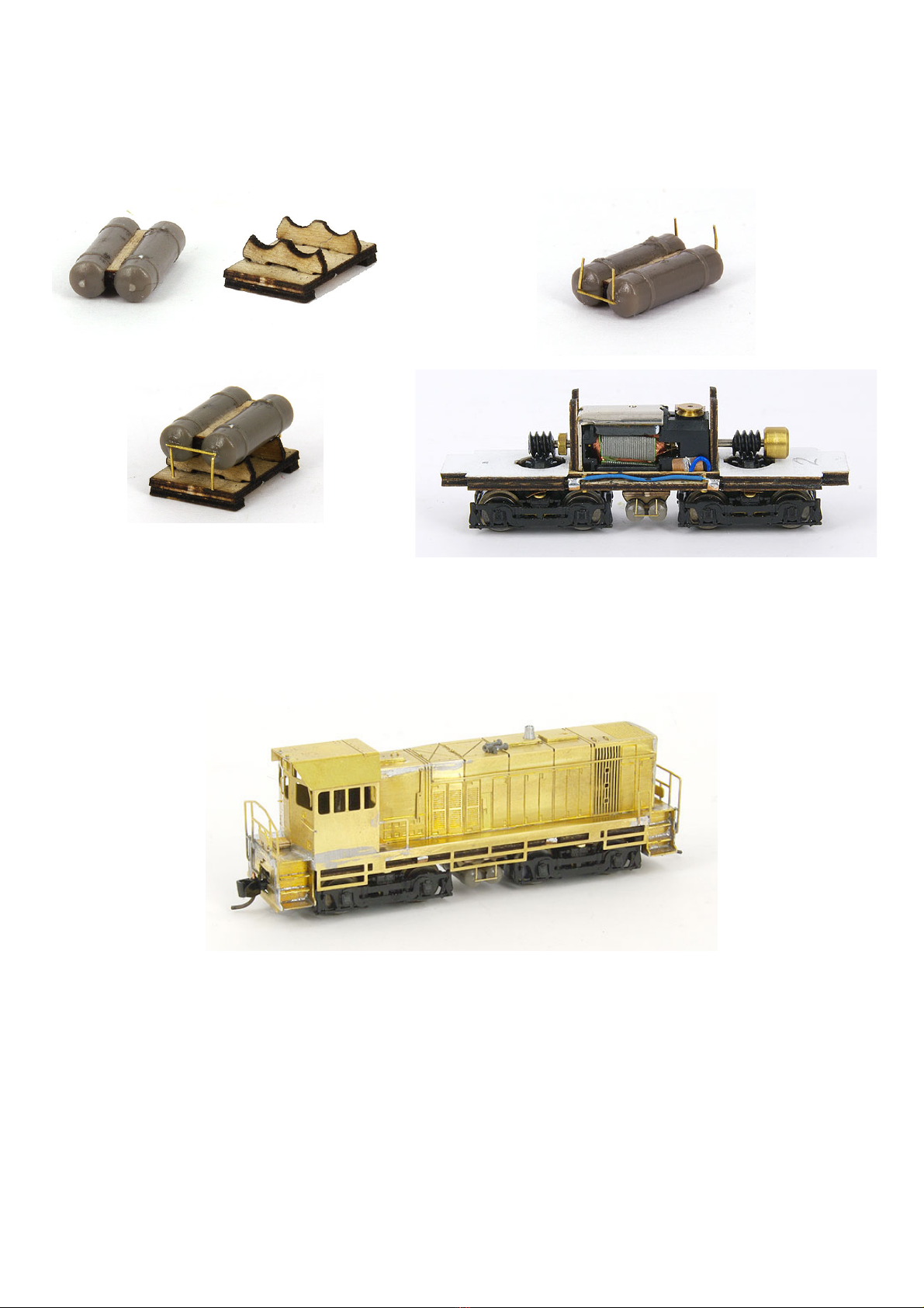
5. To install the tanks into the air tank assembly stand the pipework should be trimmed from the top leaving the ‘L’ shaped
projects from the ends of the tank. If you break or trim too much off, drill 0.3mm holes into the end caps of the tanks and
insert ‘L’ shaped 0.3mm brass wire to act as the pipes once the complete assembly has been made
6. Push a tank onto (P33) from each side evenly whilst paying attention to the spacing so that it matches the air tank
assembly stand pre-cut curves
7. Glue a 4mm piece of 0.3mm brass wire between the two air tank end pipes. See prototype photo below
8. Glue the air tanks and spacer to the air tank assembly so that the ‘L’ shaped pipes point to (P31)
9. Glue the entire assembly between the two bogies so that it spaced evenly
Assembled air tanks and air tank cradle assemblies Air tank with added pipework
Completed air tanks and cradle Air tanks and cradle in position
Final assembly:
1. Using the clear styrene fit the cab windows
2. Lightly file the sides of the original Life Like cab weight (P35) to allow it to fit inside the Y class cab
3. Glue the cab roof (P7) into place ensuring the 2 lift rings face towards the cab end
4. 2mm in from each end of the chassis is a hole that a Microtrains 1015 coupler is screwed to. Use a 0.8mm drill bit to
enlarge the hole if need be. It may take a bit of twisting and turning to get the coupler into position or you can file a very
small amount on each side and the bottom of the coupler pocket to allow the unit to slide in from the front.
Painting:
The whole etch needs to be cleaned before priming and final colour application. All excess solder should be minimised. There are
several ways of cleaning brass but to bathe the brass in warmed Vinegar for 20 minutes is recommended, then wash with fresh
water and then air dry before applying an etch primer. Some people skip the priming stage if they are using water-based acrylics.
Recommended colours - Steam Era diesel blue: Cab roof, loco, exhaust stack depending on the era. Black: Underframe.
Silver: exhaust stack depending on the era. Red: Horns trumpet end depending on the era. Weathering: is up to the builder to
decide upon.
Decals:
The chevrons and stripes are the highest quality decals on the market and have been especially screen printed for Spirit Design to
match Steam Era Diesel Yellow. Also, they feature a unique border fractionally wider than the artwork work. This means you can
cut away from the decal and when soaking off, only the artwork with the small clear border will come away. No more having to trim
as close as possible as the special mask does this for you.
The paper number plates are best trimmed as close as possible to their respective white edges and applied to the loco using
Microscale clear water-based topcoats as this acts as a glue as well as allowing you to put a water-based topcoat over an existing
enamel or water-based VR Royal Blue.
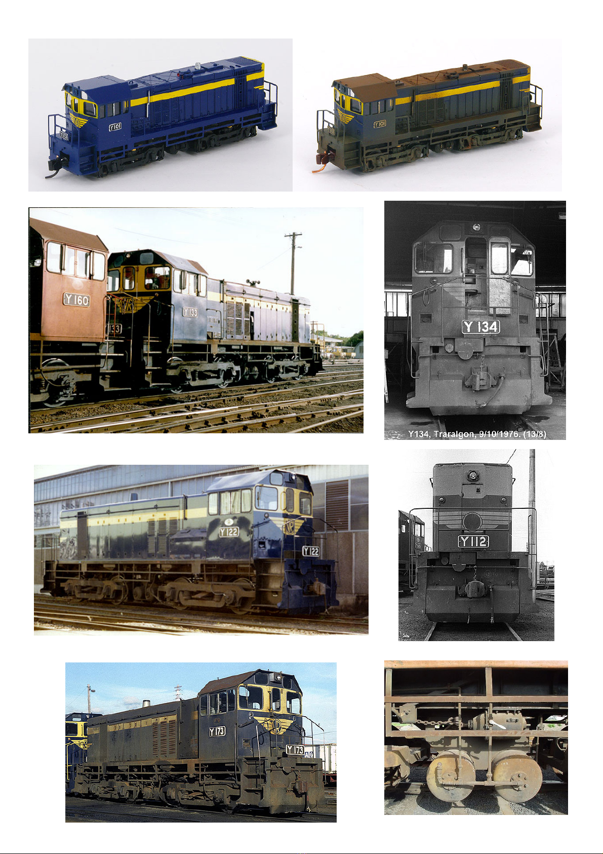
Prototype photos:
Y133 in VR and Y160 V/Line running LE at Seymour 1988. Chris Pearce Y134 Courtesy of Peter Vincent
Y 122 Dynon 1980’s. Note the fuel gauge compared to Y173 below. Chris Pearce
Long hood end of Y112; note the missing VR
in the chevron. Photo courtesy of Mark Bau.
Air tank arrangement courtesy of Peter

Above: Final series Y173 courtesy of Mark Bau. Vincent
Fuel tank pipe cab end. Photo courtesy Dave Crowhurst Fuel tank top side view. Photo courtesy Dave Crowhurst
Fireman’s side. Photo courtesy Dave Crowhurst Driver’s side. Photo courtesy Dave Crowhurst
Y139 doing what it does best. Photo courtesy of Geoff Winkler
Other SPIRIT DESIGN Toy manuals

Popular Toy manuals by other brands


Lionel
Lionel LionMaster 4-6-6-4 Challenger owner's manual

Viessmann
Viessmann 5271 Operation manual

Enabling Devices
Enabling Devices Farmer Mac user guide

E-FLITE
E-FLITE EFLU5864 manual

Mattel
Mattel Disney Pixar Cars Race Around Radiator... instructions

E-FLITE
E-FLITE F-16 Falcon 80mm EDF instruction manual