S+S Regeltechnik HYGRASREG KW Repair manual

HYGRASREG® KW
HYGRASREG® TW
D G F r
Herzlichen Glückwunsch!
Sie haben ein deutsches Qualitätsprodukt erworben.
Congratulations!
You have bought a German quality product.
Félicitations !
Vous avez fait l’acquisition d’un produit allemand de qualité.
Примите наши поздравления !
Вы приобрели качественный продукт, изготовленный в Германии.
D
Bedienungs- und Montageanleitung
Kondensationswächter, mit schaltendem Ausgang und
Taupunktwächter, mit aktivem ⁄ schaltendem Ausgang
G
Operating Instructions, Mounting & Installation
Condensation control switches with switching output
and dew point control switches with active ⁄ switching
output
F
Notice d’instruction
Contrôleur de condensation avec sortie tout ou rien et de
contrôleur de point de rosée avec sortie active ⁄ tout
ou rien
r
Руководство по монтажу и обслуживанию
Реле контроля конденсации, с релейным выходом и
Реле контроля точки росы, с активным ⁄ релейным
выходом
KW
TW
26400 -2011 02 ⁄ 2011
S+S REGELTECHNIK GMBH
PIRNAER STRASSE 20
90411 NÜRNBERG ⁄ GERMANY
FON +49 (0) 911 ⁄ 5 19 47- 0
FAX +49 (0) 911 ⁄ 5 19 47- 70
mail@SplusS.de
www.SplusS.de
HYGRASREG® KW
HYGRASREG® TW
D G F r
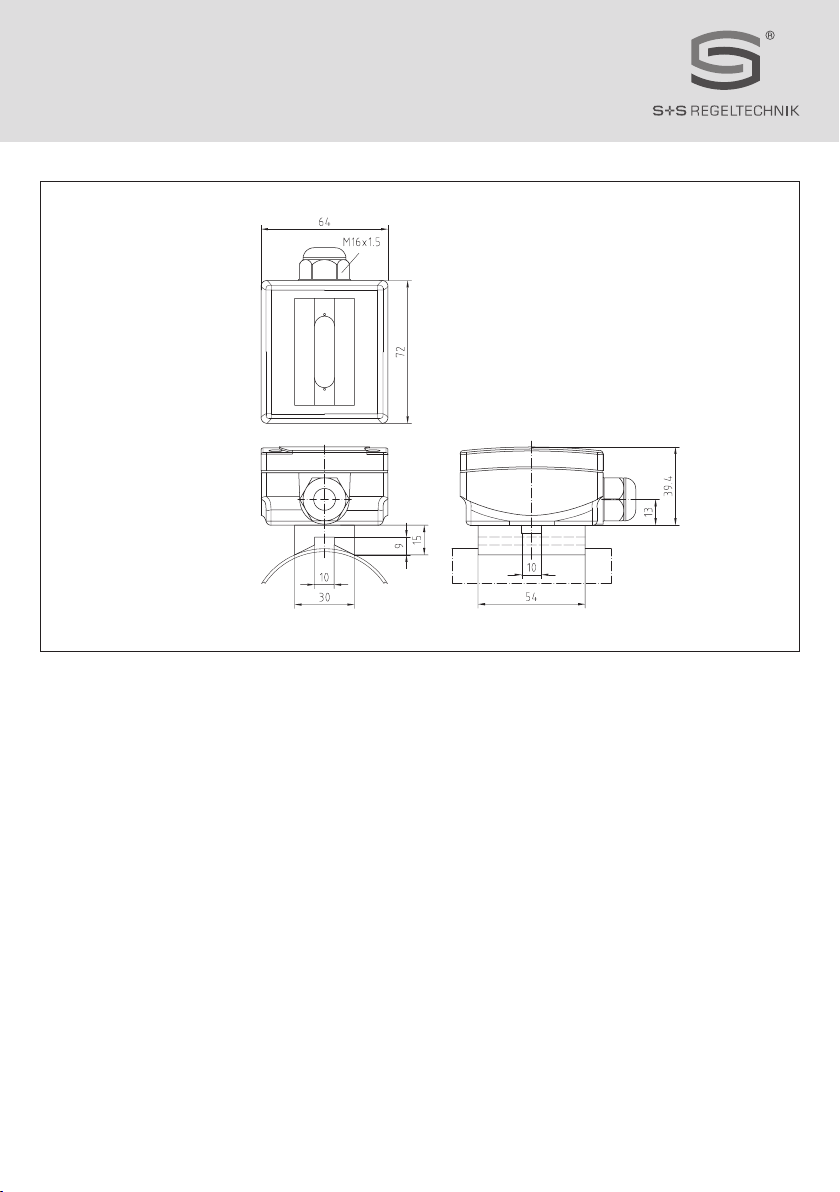
Maßzeichnung KW ⁄ TW
Dimensional drawing
Plan coté
Габаритный чертеж
Der Kondensationswächter HYGRASGARD® KW wird auf Kühldecken, Kühl- ⁄
Kalt wasserleitungen oder auf gekühlten Flächen montiert und erfasst die
Betauung. Der Kondensationsfühler soll die Kondensatbildung verhindern. Die
Taupunkt temperatur ist die Temperatur, bei der die Luft den Sättigungszu-
stand erreicht und Wasser zu kondensieren beginnt. Der HYGRASGARD® KW
kann als Wächter an Kühldecken oder Rohrleitungen so betrieben werden,
dass bei Betauung der Kühl decken bzw. des zu überwachenden Objektes der
Schaltausgang aktiviert wird und dadurch z. B. die Heizung zuschaltet oder an-
dere Stellglieder.
TECHNISCHE DATEN:
Spannungsversorgung: ............. 24 V AC ⁄ DC
Schaltschwelle: ...........................ca. 95 % r. H.
Eigenstrombedarf: ..................... max. 20 mA
Ausgangssignal: ..........................potentialfreier Wechsler (24 V)
Prozessanschluss: ..................... Endlosspannband mit Schloss aus Metall,
300 mm, für Rohre bis 3 ''
(ist im Lieferumfang enthalten)
elektrischer Anschluss: ............0,14 - 1,5 mm², über Schraubklemmen
Gehäuse: ...................................... aus Kunststoff, Werkstoff Polyamid,
30 % glaskugelverstärkt,
mit Schnellverschlussschrauben,
Farbe reinweiß (ähnlich RAL 9010)
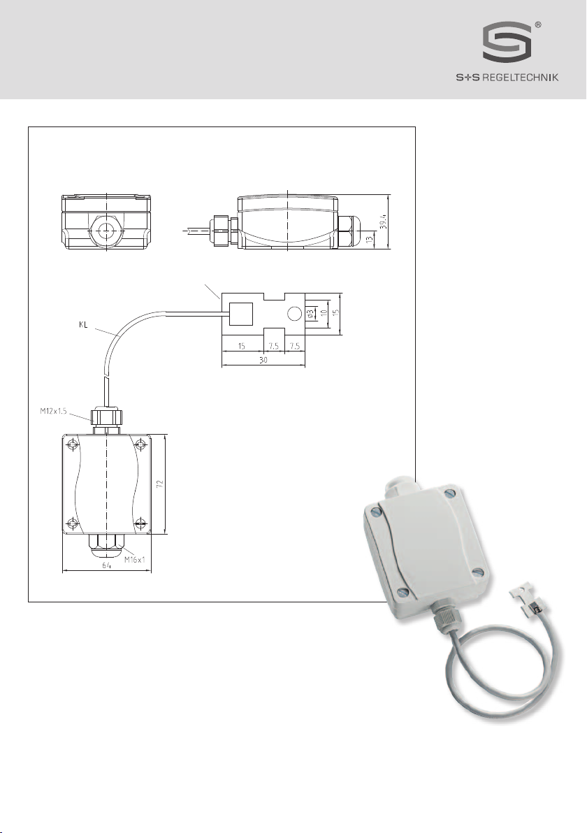
Abmaße: .......................................72 x 64 x 39,4 mm
Kabelverschraubung: ................. M16, mit Zugentlastung
Schutzklasse: ..............................III (nach EN 60 730)
Schutzart: ....................................IP 65 (nach EN 60 529)
Normen: .......................................CE-Konformität,
elektromagnetische Verträglichkeit
nach EN 61 326 + A1 + A2,
EMV-Richtlinie 2004 ⁄ 108 ⁄ EC
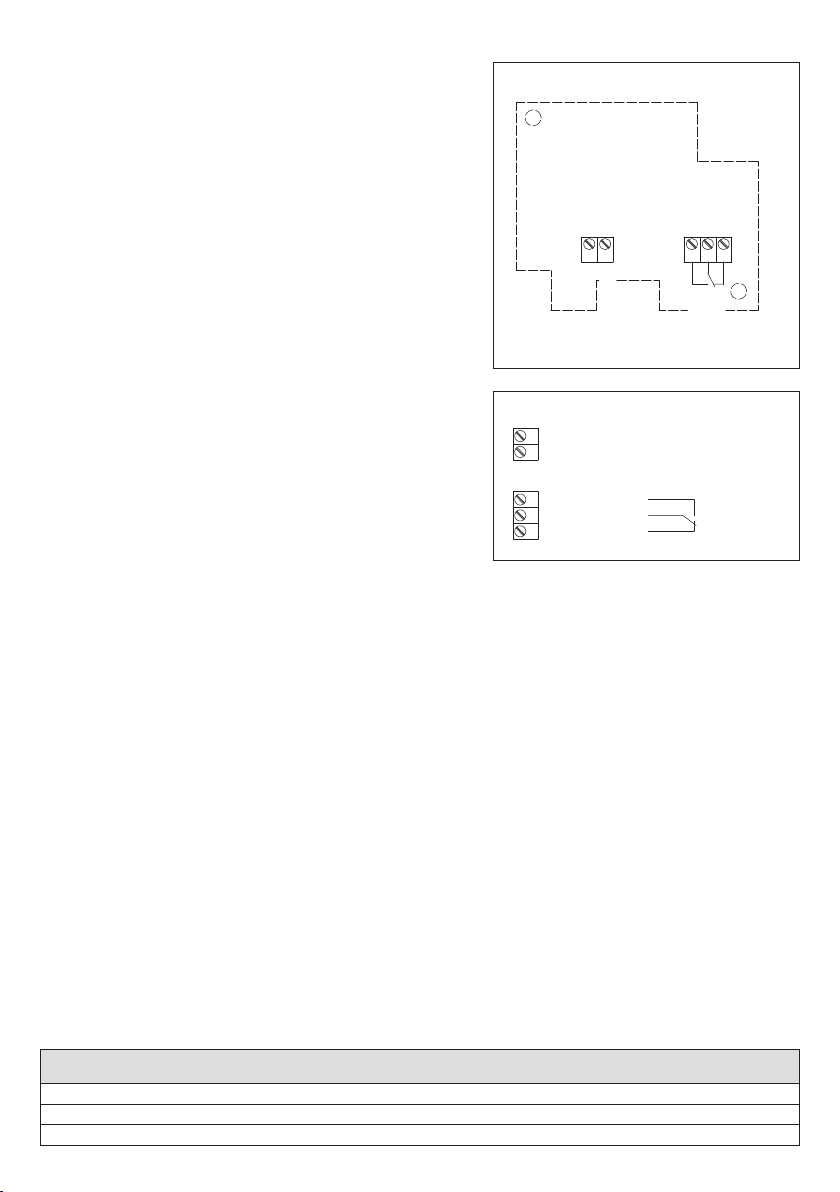
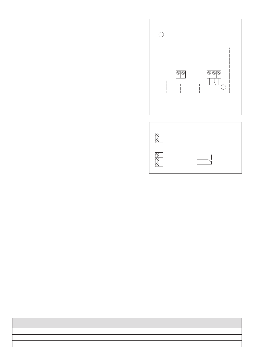
Schaltbild KW - W - x
Anschlussbild KW - W - x
D HYGRASREG® KW
Typ ⁄ WG1 Messbereich Ausgang Sensor Montageart
Feuchte (relativ) Feuchte (relativ)
KW- W - Rohr ca. 95 % r. H. Wechsler intern zur direkten Rohrmontage
KW- W - Wand ca. 95 % r. H. Wechsler intern zur direkten Wandmontage
KW- W - extern ca. 95 % r. H. Wechsler extern zur Rohrmontage
12 7 89
Schliesser
Öffner
Schaltpunkt
ca. 95% r.H.
GND
UB+ 24V AC/DC
1
2
7
8
9
UB- GND
Schliesser
Öffner
UB+ Versorgungsspannung 24V AC/DC

Der Taupunktwächter HYGRASGARD® TW wird auf Kühl- ⁄ Kaltwasserleitungen
oder auf kühlen Flächen montiert. Er kann als Feuchtefühler, Taupunktsensor,
Taupunkt fühler oder Grenzwertschalter an Rohren benutzt werden. Die Tau-
punkttemperatur ist die Temperatur, bei der die Luft den Sättigungszustand
erreicht und Wasser zu kondensieren beginnt. Durch den stetigen Messbe-
reich von 0...100 % r. H. beim TW-U und dem einstellbaren Grenzwert beim
TW-W von 80...100 %, können z. B. Kühldecken so betrieben werden, dass vor
der Betauung der Rohre oder Kühldecken bzw. des zu überwachenden Objek-
tes der Schaltausgang des Taupunktwächters, der DDC aktiviert wird, dadurch
z. B. die Heizung oder andere Stellglieder zuschalten und somit eine Betauung
verhindert wird. Die Feuchte wird mit einem digitalen, langzeitstabilen Feuchte- ⁄
Temperatursensor erfasst.
TECHNISCHE DATEN:
Spannungsversorgung: ............. 24 V AC ⁄ DC
Messbereich: .............................. 0 …100 % r. H., TW-U, stetig
80 …100 % r. H., TW-W, einstellbar,
detektiert wird die Betauung,
der Schaltwert kann über ein Poti eingestellt
werden
Eigenstrombedarf: ..................... 5 mA, mit Relais max. 20 mA
Sensoren: ....................................digitaler Feuchtesensor,
mit integriertem Temperatursensor,
betauungsfest, kleine Hysterese,
hohe Langzeitstabilität
Sensorschutz: .............................Membranfilter
Ausgangssignal: ..........................0 -10 V oder potentialfreier Wechsler (24 V)
Prozessanschluss: ..................... Endlosspannband mit Schloss aus Metall,
300 mm, für Rohre bis 3 ''
(ist im Lieferumfang enthalten)
elektrischer Anschluss: ............0,14 - 1,5 mm², über Schraubklemmen
Gehäuse: ...................................... aus Kunststoff, Werkstoff Polyamid,
30 % glaskugelverstärkt,
mit Schnellverschlussschrauben,
Farbe reinweiß (ähnlich RAL 9010)
Abmaße: .......................................72 x 64 x 39,4 mm
Kabelverschraubung: ................. M16, mit Zugentlastung
Schutzklasse: ..............................III (nach EN 60 730)
Schutzart: ....................................IP 65 (nach EN 60 529)
Normen: .......................................CE-Konformität,
elektromagnetische Verträglichkeit
nach EN 61 326 + A1 + A2,
EMV-Richtlinie 2004 ⁄ 108 ⁄ EC
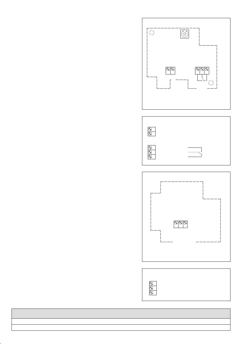
Schaltbild TW - W
Schaltbild TW - U
Anschlussbild TW - W
Anschlussbild TW - U
D HYGRASREG® TW
Typ ⁄ WG1 Messbereich Ausgang
Feuchte (relativ) Feuchte (relativ)
TW- U 0 …100 % r. H. 0 -10 V
TW- W 80 …100 % r. H. Wechsler
12789
min.
80%
max.
100%
Einstellung
Schaltpunkt
80% - 100% r.H.
Schliesser
Öffner
GND
UB= 24V AC/DC
1
2
7
8
9
UB- GND
Schliesser
Öffner
UB+ Versorgungsspannung 24V AC/DC
124
GND
UB= 24V AC/DC
Ausgang Betauung
0-10V
1
2
4
UB- GND
UB+ Versorgungsspannung 24V AC/DC
Ausgang Betauung 0-10V (stetig)
D Wichtige Hinweise
– Dieses Gerät darf nur in schadstofffreier, nicht kondensierender Luft, ohne Über- oder Unterdruck am Sensorelement eingesetzt werden.
– Bei Aussen- und Kanalfühlern schützt der Sinterfilter des Sensorelementes den Feuchtesensor vor eventuellen Staub belastungen.
Dieser Filter sollte bei Verunreinigung ⁄ Verschmutzung regelmäßig gewartet werden.
– Staub- und Verunreinigungen verfälschen das Messergebnis und sind zu vermeiden.
Geringe Verunreinigungen und Staubablagerungen können mit Druckluft beseitigt werden.
– Das Berühren des Feuchteelementes ist unbedingt zu vermeiden, da dies zu erheblichen Fehlmessungen führt.
– Bei Verunreinigungen empfehlen wir eine werksseitige Reinigung und Neukalibrieung.
– Chemikalien oder andere Reinigungsmittel dürfen unter keinen Umständen auf den Sensor gelangen.
– Die relative Feuchte von 0 ...100 % wird durch das Ausgangssignal von 0 -10 V abgebildet. Der Arbeitsbereich des Gerätes umfasst 10 ... 95 % r. H.,
ausserhalb dieses Bereiches kann es zu Fehlmessungen bzw. zu erhöhten Abweichungen kommen.
–
Beim Anschluss mehrerer Fühler (0 -10 V) an eine gemeinsame Spannungsversorgung mit 24 V AC (Wechselspannung) ist auf die Polung zu achten, da
sonst die Wechselspannungsquelle kurz geschlossen werden kann. Die Spannungsausgänge sind kurzschlussfest, ein Anlegen einer Über spannung
oder der Spannungsversorgung am Spannungsausgang zerstört das Gerät.
– Beim Betrieb des Gerätes ausserhalb des Spezifikationsbereiches entfallen alle Garantieansprüche.
Als AGB gelten ausschließlich unsere sowie die gültigen „Allgemeinen Lieferbedingungen für Erzeugnisse und Leistungen der Elektro industrie“
(ZVEI Bedingungen) zuzüglich der Ergänzungsklausel „Erweiterter Eigentumsvorbehalt“.
Außerdem sind folgende Punkte zu beachten:
– Vor der Installation und Inbetriebnahme ist diese Anleitung zu lesen und die alle darin gemachten Hinweise sind zu beachten!
– Der Anschluss der Geräte darf nur an Sicherheitskleinspannung und im spannungslosen Zustand erfolgen. Um Schäden und Fehler am Gerät
(z.B. durch Spannungsinduktion) zu verhindern, sind abgeschirmte Leitungen zu verwenden, eine Parallelverlegung zu stromführenden Leitungen zu
vermeiden und die EMV- Richtlinien zu beachten.
– Dieses Gerät ist nur für den angegebenen Verwendungszweck zu nutzen, dabei sind die entsprechenden Sicherheitsvorschriften des VDE,
der Länder, ihrer Überwachungsorgane, des TÜV und der örtlichen EVU zu beachten.
Der Käufer hat die Einhaltung der Bau- und Sicherungsbestimmung zu gewährleisten und Gefährdungen aller Art zu vermeiden.
– Für Mängel und Schäden, die durch unsachgemäße Verwendung dieses Gerätes entstehen, werden keinerlei Gewährleistungen und Haftungen
übernommen.
– Folgeschäden, welche durch Fehler an diesem Gerät entstehen, sind von der Gewährleistung und Haftung ausgeschlossen.
– Die Installation der Geräte darf nur durch Fachpersonal erfolgen.
– Es gelten ausschließlich die technischen Daten und Anschlussbedingungen der zum Gerät gelieferten Montage- und Bedienungs anleitung,
Abweichungen zur Katalogdarstellung sind nicht zusätzlich aufgeführt und im Sinne des technischen Fortschritts und der stetigen Verbesserung
unserer Produkte möglich.
– Bei Veränderungen der Geräte durch den Anwender entfallen alle Gewährleistungsansprüche.
– Dieses Gerät darf nicht in der Nähe von Wärmequellen (z.B. Heizkörpern) oder deren Wärmestrom eingesetzt werden, eine direkte Sonnen-
einstrahlung oder Wärmeeinstrahlung durch ähnliche Quellen (starke Leuchte, Halogenstrahler) ist unbedingt zu vermeiden.
– Der Betrieb in der Nähe von Geräten, welche nicht den EMV- Richtlinien entsprechen, kann zur Beeinflussung der Funktionsweise führen.
– Dieses Gerät darf nicht für Überwachungszwecke, welche ausschließlich dem Schutz von Personen gegen Gefährdung oder Verletzung dienen und
nicht als Not-Aus-Schalter an Anlagen und Maschinen oder vergleichbare sicherheitsrelevante Aufgaben verwendet werden.
– Die Gehäuse- und Gehäusezubehörmaße können geringe Toleranzen zu den Angaben dieser Anleitung aufweisen.
– Veränderungen dieser Unterlagen sind nicht gestattet.
– Reklamationen werden nur vollständig in Originalverpackung angenommen.
Vor der Installation und Inbetriebnahme ist diese Anleitung zu lesen und die alle darin gemachten Hinweise sind zu beachten!
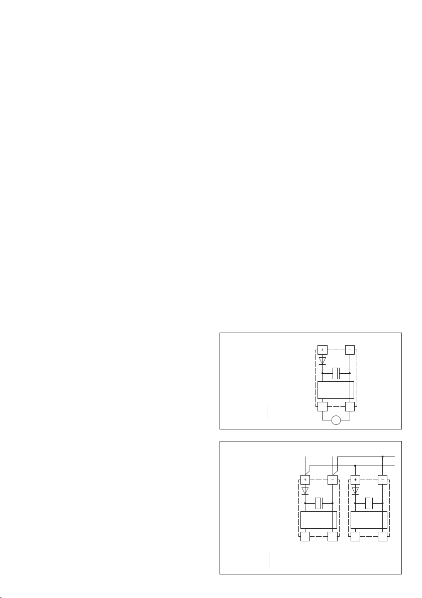
Schaltbild Parallelbetrieb
Schaltbild Einzelbetrieb
VERSORGUNGSSPANNUNG:
Als Verpolungsschutz der Betriebsspannung ist bei dieser Gerätevariante
eine Einweggleichrichtung bzw. Verpolungschutzdiode integriert. Diese
interne Einweggleichrichtung erlaubt auch den Betrieb mit AC-Versor-
gungsspannung bei 0 - 10 V Geräten.
Das Ausgangssignal ist mit einem Messgerät abzugreifen. Hierbei wird
die Ausgangsspannung gegen das Nullpotenial (O V) der Eingangsspan-
nung ge messen!
Wird dieses Gerät mit DC - Versorgungsspannung betrieben, ist der
Betriebsspannungseingang UB+ für 15...36 V DC - Einspeisung und UB–
bzw. GND als Masseleitung zu verwenden!
Werden mehrere Geräte von einer 24 V AC - Spannung versorgt, ist
darauf zu achten, dass alle „positiven“ Betriebsspannungseingänge (+)
der Feldgeräte miteinander verbunden sind, sowie alle „negativen“ Be-
triebsspannungseingänge (–) = Bezugspotential miteinander ver bunden
sind (phasengleicher Anschluss der Feldgeräte). Alle Feld ge räte aus-
gänge müssen auf das gleiche Potential bezogen werden!
Bei Verpolung der Versorgungsspannung an einem der Feldgeräte
würde über dieses ein Kurzschluss der Versorgungsspannung erzeugt.
Der somit über dieses Feldgerät fließende Kurzschlussstrom kann zur
Beschädigung dieses Gerätes führen.
Achten Sie daher auf die korrekte Verdrahtung! Schaltung Schaltung
0-10V
0V/GND
0-10V
0V/GND
Versorgung mit
AC 24V~ 0V
DC 15-36V = GND
AC 24V~ 0V
DC 15-36V = GND
Schaltung
0-10V
0V/GND
V
Versorgung mit

The condensation control switch HYGRASREG® KW is installed on cooling
ceilings, on cooling or coldwater piping, or on cooled surfaces to detect gen-
eration of dew. This condensation sensor is designed to prevent condensate
formation. Dew point temperature is that temperature at which air reaches
the state of saturation and water starts to precipitate. HYGRASREG® KW
can be operated as monitor on cooling ceilings or pipes so that the switching
output is activated when dew is building up on the cooling ceilings of the object
to be monitored and e.g. a heating system is started, or other actuators are
initiated.
TECHNICAL DATA:
Power supply: ..............................24 V AC ⁄ DC
Switching threshold: .................. ca. 95 % r. H.
Internal current consumption: ....
max. 20 mA
Output signal: .............................. potential-free changeover contact (24 V)
Process connection: .................. endless metal strap with metal tightener,
300 mm, for pipes up to 3 " diameter
(included in the scope of delivery)
Electrical connection: ................0.14 - 1.5 mm², via terminal screws
Enclosure: ....................................plastic, material polyamide,
30 % glass-globe-reinforced,
with quick-locking screws,
colour pure white (similar RAL 9010)
Dimensions: .................................72 x 64 x 39.4 mm
Cable gland: ................................. M16, including strain relief
Protection class: ........................III (according to EN 60 730)
Protection type:.......................... IP 65 (according to EN 60 529)
Standards: ...................................CE conformity,
electromagnetic compatibility
according to EN 61 326 + A1 + A2,
EMC directive 2004 ⁄ 108 ⁄ EC
Schematic diagram KW - W - x
Connecting diagram KW - W - x
Type ⁄ WG1 Measuring Range Output Sensor Mounting
Humidity (relative) Humidity (relative)
KW- W - Pipe ca. 95 % r. H. Changeover contact internal for mounting directly on pipes
KW- W - Wall ca. 95 % r. H. Changeover contact internal for mounting directly on walls
KW- W - external ca. 95 % r. H. Changeover contact external for mounting on pipes
12 7 89
Normally open
contact
Breaker
Switchpoint
ca. 95% r.H.
GND
UB+ 24V AC/DC
1
2
7
8
9
UB- GND
Normally open
contact
Breaker
UB+ supply voltage 24V AC/DC
G HYGRASREG® KW
The dew point control switch HYGRASGARD® TW is installed on cooling or
coldwater piping or on cooled surfaces. It can be used as moisture sensor,
dew point sensor, dew point detector, or limit value switch on pipes. Dew
point temperature is that temperature at which air reaches the state of
saturation and water starts to pre ci pitate. Because of the continuous meas-
uring range of 0...100 % r.H. at the TW-U variant and the adjustable limit
value of 80...100 % r.H. at the TW-W variant, cooling ceilings for example can
be operated so that generation of dew on pipes or cooling ceilings or other
parts of the object to be monitored is prevented by activating the switching
output of the dew point control switch, the DDC, and thus, a heating system
or other actuators are activated, preventing the generation of dew. Moisture
is detected by a digital long-term stable humidity ⁄ temperature sensor.
TECHNICAL DATA:
Power supply: ..............................24 V AC ⁄ DC
Measuring Range: ...................... 0 …100 % r. H., TW-U, continuous
80 …100 % r. H., TW-W, adjustable,
generation of dew is detected,
switching value can be adjusted
via potentiometer
Internal current consumption: ....
5 mA, with relay max. 20 mA
Sensors: .......................................digital humidity sensor
with integrated temperature sensor,
dew-proof, small hysteresis,
high long-term stability
Sensor protection: ..................... membrane filter
Output signal: .............................. 0 -10 V or potential-free
changeover contact (24 V)
Process connection: .................. endless metal strap with metal tightener,
300 mm, for pipes up to 3 " diameter
(included in the scope of delivery)
Electrical connection: ................0.14 - 1.5 mm², via terminal screws
Enclosure: ....................................plastic, material polyamide,
30 % glass-globe-reinforced,
with quick-locking screws,
colour pure white (similar RAL 9010)
Dimensions: .................................72 x 64 x 39.4 mm
Cable gland: ................................. M16, including strain relief
Protection class: ........................III (according to EN 60 730)
Protection type:.......................... IP 65 (according to EN 60 529)
Standards: ...................................CE conformity,
electromagnetic compatibility
according to EN 61 326 + A1 + A2,
EMC directive 2004 ⁄ 108 ⁄ EC
Schematic diagram TW - W
Schematic diagram TW - U
Connecting diagram TW - W
Connecting diagram TW - U
Type ⁄ WG1 Measuring Range Output
Humidity (relative) Humidity (relative)
TW- U 0 …100 % r. H. 0 -10 V
TW- W 80 …100 % r. H. Changeover contact
12789
min.
80%
max.
100%
Switchpoint
setting
80% - 100% r.H.
Normally open
contact
Breaker
GND
UB= 24V AC/DC
1
2
7
8
9
UB- GND
Normally open
contact
Breaker
UB+ supply voltage 24V AC/DC
124
GND
UB= 24V AC/DC
Output bedewing
0-10V
1
2
4
UB- GND
UB+ supply voltage 24V AC/DC
Output bedewing 0-10V (continuous)
G HYGRASREG® TW

G General notes
– This device must only be used in non-precipitating air without above-atmospheric or below-atmospheric pressure at the sensor element.
– On outdoor and duct sensors, the sinter filter of the senor element protects the humidity sensor against potential dust exposure.
In case of pollution ⁄ contamination, this filter should be cleaned on a regular basis.
– Dust and pollution falsify measurement results and are to be avoided. Slight pollution and dust sediments can be removed by using compressed air.
– Touching the humidity element is under any circumstances to be avoided, as that would result in considerable mismeasurements.
– In case of pollution, we recommend cleaning and recalibration in the factory.
– In any case, the sensor must not get in contact with chemicals or other cleaning agents.
– The relative humidity of 0...100 % is indicated by an output signal of 0 -10 V or 4 ... 20 mA.
– The device operating range covers 10.0 ... 99.9 % r. H. Beyond that range, mismeasurements or increased deviations may occur.
– When several sensors (0 -10 V) are connected to one voltage supply of 24 V AC, correct polarity must be regarded as otherwise the alternating
voltage source may be short-circuited.
– The voltage outputs are short-circuit proof. Applying overvoltage or voltage supply to the voltage output will destroy the device.
– If this device is operated beyond the specified range, all warranty claims are forfeited.
Our “General Terms and Conditions for Business“ together with the “General Conditions for the Supply of Products and Services of the Electrical and
Electronics Industry“ (ZVEI conditions) including supplementary clause “Extended Retention of Title“ apply as the exclusive terms and conditions.
In additionIn addition, the following points are to be observed:
– These instructions must be read before installation and putting in operation and all notes provided therein are to be regarded!
– Devices must only be connected to safety extra-low voltage and under dead-voltage condition. To avoid damages and errors the device (e.g. by voltage
induction) shielded cables are to be used, laying parallel with current-carrying lines is to be avoided, and EMC directives are to be observed.
– This device shall only be used for its intended purpose. Respective safety regulations issued by the VDE, the states, their control authorities, the TÜV
and the local energy supply company must be observed. The purchaser has to adhere to the building and safety regulations and has to prevent perils
of any kind.
– No warranties or liabilities will be assumed for defects and damages arising from improper use of this device.
– Consequential damages caused by a fault in this device are excluded from warranty or liability.
– These devices must be installed by authorised specialists only.
– The technical data and connecting conditions of the mounting and operating instructions delivered together with the device are exclusively valid.
Deviations from the catalogue representation are not explicitly mentioned and are possible in terms of technical progress and continuous improve-
ment of our products.
– In case of any modifications made by the user, all warranty claims are forfeited.
– This device must not be installed close to heat sources (e.g. radiators) or be exposed to their heat flow. Direct sun irradiation or heat irradiation by
similar sources (powerful lamps, halogen spotlights) must absolutely be avoided.
– Operating this device close to other devices that do not comply with EMC directives may influence functionality.
– This device must not be used for monitoring applications, which solely serve the purpose of protecting persons against hazards or injury, or as an
EMERGENCY STOP switch for systems or machinery, or for any other similar safety-relevant purposes.
– Dimensions of enclosures or enclosure accessories may show slight tolerances on the specifications provided in these instructions.
– Modifications of these records are not permitted.
– In case of a complaint, only complete devices returned in original packing will be accepted.
These instructions must be read before installation and putting in operation and all notes provided therein are to be regarded!
Connecting scheme Parallel operation
Connecting scheme Individual operation
SUPPLY VOLTAGE:
For operating voltage reverse polarity protection, a one-way rectifier or
reverse polarity protection diode is integrated in this device variant.
This internal one-way rectifier also allows operating 0 – 10 V devices on
AC supply voltage.
The output signal is to be tapped by a measuring instrument. Output
voltage is measured her against zero potential (O V) of the input voltage!
When this device is operated on DC supply voltage, the operating volt-
age input UB+ is to be used for 15...36 V DC supply and UB – or GND for
ground wire!
When several devices are supplied by one 24 V AC voltage supply, it is
to be ensured that all ”positive“ operating voltage input terminals (+) of
the field devices are connected with each other and all ”negative“ opera-
ting voltage input terminals (–) (= reference potential) are connected
together (in-phase connection of field devices). All outputs of field de-
vices must be referenced to the same potential!
In case of reversed polarity at one field device, a supply voltage short-
circuit would be caused by that device. The consequential short-circuit
current flowing through this field device may cause damage to it.
Therefore, pay attention to correct wiring! Circuitry Circuitry
0...10V
0V/GND
0...10V
0V/GND
Power supply
AC 24V~ 0V
DC 15-36V = GND
Circuitry
0...10V
0V/GND
V
Power supply
AC 24V~ 0V
DC 15-36V = GND

Le contrôleur de condensation HYRASREG® KW est monté sur des plafonds
frigorifiques et des conduites frigorifiques/d'eau froide, et il mesure le point
de rosée. La sonde de condensation est conçue pour éviter la formation de
condensation. La température de rosée est la température à laquelle l'air
atteint le point de saturation et où l'eau commence à se condenser. Le
HYGRASREG® KW peut être monté sur des plafonds frigorifiques ou sur des
tuyauteries et utilisé de manière que lors du dépôt de rosée sur ces plafonds
ou sur l'objet à surveiller, la sortie de commutation sera activée, faisant ainsi
fonctionner le chauffage ou d'autres actionneurs électriques.
CARACTERISTIQUES TECHNIQUES:
Tension d'alimentation: .............. 24 V ca ⁄ cc
Seuil de commutation: ............... ca. 95 % r. H.
Consommation de courant: ...... max. 20 mA
Signal de sortie:.......................... inverseur libre de potentiel (24 V)
Raccordement process: ...........collier de serrage sans fin avec verrouillage
en métal, 300 mm, pour tuyaux jusqu'à 3"
(compris dans la livraison)
Raccordement électrique: ........0,14 - 1,5 mm², par bornes à vis
Boîtier: .........................................en matière plastique, polyamide,
renforcé à 30% de billes de verre,
avec vis de fermeture rapide,
couleur blanc pur (similaire à RAL 9010)
Dimensions: .................................72 x 64 x 39,4 mm
Presse-étoupe: ........................... M16, avec décharge de traction
classe de protection: .................III (selon EN 60 730)
Indice de protection: ..................IP 65 (selon EN 60 529)
Normes: .......................................Conformité CE,
Compatibilité électromagnétique
selon EN 61 326 + A1 + A2,
Directive "CEM" 2004 ⁄ 108 ⁄ EC
Schéma de raccordement KW - W - x
Schéma de raccordement KW - W - x
Désignation ⁄ WG1 plage de mesure sortie capteur type de montage
humidité (relative) humidité (relative)
KW- W - tube env. 95 % h. r. inverseur interne pour montage direct sur tube
KW- W - mur env. 95 % h. r. inverseur interne pour montage direct sur mur
KW- W - externe env. 95 % h. r. inverseur externe pour montage sur tube
12 7 89
Normally open
contact
Breaker
Switchpoint
ca. 95% r.H.
GND
UB+ 24V AC/DC
1
2
7
8
9
UB- GND
Normally open
contact
Breaker
UB+ supply voltage 24V AC/DC
F HYGRASREG® KW

Le contrôleur de point de rosée HYGRASGARD® TW est monté sur des
conduites frigorifiques ⁄ d’eau froide ou sur des surfaces refroidies. Il peut
être utilisé comme sonde d’humidité, comme capteur de point de rosée,
sonde de point de rosée ou détecteur de seuil sur des tuyaux. La tempéra-
ture de rosée est la température à laquelle l’air devient saturant et à
laquelle l’eau commence à se condenser. Grâce à la plage de mesure analo-
gique de 0 à 100 % h.r. du TW - U et étant donné que la valeur limite du
TW - W est réglable entre 80 et 100 %, des plafonds frigorifiques par ex.
peuvent être utilisés de façon qu’avant le dépôt de rosée sur les tuyaux ou
sur les plafonds frigorifiques et ⁄ ou sur l’objet à surveiller, la sortie de com-
mutation du contrôleur de point de rosée (du DDC) est activée, faisant fonc-
tionner le chauffage ou d’autres actionneurs électriques et évitant ainsi le
dépôt de rosée. L’ humidité est mesurée avec un capteur d’humidité-tempé-
rature numérique à haute stabilité long terme.
CARACTÉRISTIQUES TECHNIQUES:
Tension d’alimentation: .............. 24 V ca ⁄ cc
Plage de mesure: .......................0 …100 % h.r., TW-U, analogique
80 …100 % h.r., TW-W, réglable,
le point de rosée est détecté,
la valeur de seuil peut être réglée
par un potentiomètre
Consommation de courant: ...... 5 mA, avec relais 20 mA maxi
Capteurs: .....................................capteur d'humidité numérique,
avec capteur de température intégré,
résistant à la condensation, faible hysteresis,
haute stabilité long terme
Protection de capteur: .............. Filtre à membrane
Signal de sortie:.......................... 0 -10 V ou inverseur libre de potentiel (24 V)
Raccordement process: ...........collier de serrage sans fin
avec verrouillage en métal,
300 mm, pour tuyaux jusqu’à 3 ''
(compris dans la livraison)
Raccordement électrique: ........0,14 - 1,5 mm², par bornes à vis
Boîtier: .........................................en matière plastique, polyamide,
renforcé à 30 % de billes de verre,
avec vis de fermeture rapide,
couleur blanc pur (similaire à RAL 9010)
Dimensions: .................................72 x 64 x 39,4 mm
Presse-étoupe: ........................... M16, avec décharge de traction
Classe de protection: ................III (selon EN 60 730)
Indice de protection: ..................IP 65 (selon EN 60 529)
Normes: .......................................conformité CE,
compatibilité électromagnétique
selon EN 61 326 + A1 + A2,
Directive « CEM » 2004 ⁄ 108 ⁄ CE
Schéma de raccordement TW - W
Schéma de raccordement TW - U
Schéma de raccordement TW - W
Schéma de raccordement TW - U
Désignation ⁄ WG1 plage de mesure sortie
humidité (relative) humidité (relative)
TW- U 0 …100 % h.r. 0 -10 V
TW- W 80 …100 % h.r. inverseur
12789
min.
80%
max.
100%
Switchpoint
setting
80% - 100% r.H.
Normally open
contact
Breaker
GND
UB= 24V AC/DC
1
2
7
8
9
UB- GND
Normally open
contact
Breaker
UB+ supply voltage 24V AC/DC
124
GND
UB= 24V AC/DC
Output bedewing
0-10V
1
2
4
UB- GND
UB+ supply voltage 24V AC/DC
Output bedewing 0-10V (continuous)
F HYGRASREG® TW

F Généralités
–
Cet appareil ne doit être utilisé que dans un air non pollué, sans risque de condensation, sans risque de surpression ou dépression sur l’élément sensible.
–
Dans le cas des sondes extérieures et des sondes pour montage en gaine, le filtre fritté de l’élément sensible protège la sonde d’humidité contre la
pénétration des particules de poussières. Il est conseillé de nettoyer le filtre régulièrement des impuretés.
–
Il faut éviter la présence de poussières et d’impuretés, puisqu’elles altèrent le résultat de mesure.
De faibles quantités d’impuretés et de poussières dépo-sées peuvent être éliminées par soufflage à l’air comprimé.
–
Il faut impérativement éviter de toucher le capteur d’humidité, car ceci provoquerait de graves erreurs de mesure.
–
En cas d’impuretés, il est conseillé de procéder à un nettoyage à l’usine et de l’étalonner à nouveau.
–
En aucun cas, le capteur ne doit entrer en contact avec des produits chimiques ou d’autres détergents.
–
L’humidité relative de 0…100 % est représenté par le signal de sortie 0 -10 V . La plage de fonctionnement de l’appareil va de 10,0 jusqu’à 95 % h.r.,
une utilisation en dehors de cette plage peut entraîner des mesures erronées ou des incertitudes de mesure plus élevées.
–
Si plusieurs sondes (0 -10 V) sont connectées à une seule source d’alimentation en courant alternatif 24 V, il faut respecter la polarisation,
car sinon la source de tension alternative peut être mise en court-circuit. Les sorties en tension sont protégées contre les courts - circuits,
l’application d’une surtension ou l’application de la tension d’alimentation à la sortie en tension causera la destruction de l’appareil.
–
Nous déclinons toute garantie dans le cas où l’appareil serait utilisé en dehors de la plage des spécifications.
Seules les CGV de la société S+S, les « Conditions générales de livraison du ZVEI pour produits et prestations de l’industrie électronique » ainsi que la
clause complémentaire « Réserve de propriété étendue » s’appliquent à toutes les relations commerciales entre la société S+S et ses clients.
Il convient en outre de respecter les points suivants :
–
Avant de procéder à toute installation et à la mise en service, veuillez lire attentivement la présente notice et toutes les consignes qui y sont précisées !
– Les raccordements électriques doivent être exécutés HORS TENSION. Ne branchez l’appareil que sur un réseau de très basse tension de sécurité.
Pour éviter des endommagements ⁄ erreurs sur l’appareil (par ex. dus à une induction de tension parasite), il est conseillé d’utiliser des câbles
blindés, ne pas poser les câbles de sondes en parallèle avec des câbles de puissance, les directives CEM sont à respecter.
– Cet appareil ne doit être utilisé que pour l’usage qui est indiqué en respectant les règles de sécurité correspondantes de la VDE, des Länders,
de leurs organes de surveillance, du TÜV et des entreprises d’approvisionnement en énergie locales. L’acheteur doit respecter les dispositions
relatives à la construction et à la sécurité et doit éviter toutes sortes de risques.
– Nous déclinons toute responsabilité ou garantie pour les défauts et dommages résultant d’une utilisation inappropriée de cet appareil.
– Nous déclinons toute responsabilité ou garantie au titre de tout dommage consécutif provoqué par des erreurs commises sur cet appareil.
– L’installation des appareils doit être effectuée uniquement par un spécialiste qualifié.
– Seules les données techniques et les conditions de raccordement indiquées sur la notice d’instruction accompagnant l’appareil sont applicables,
des différences par rapport à la présentation dans le catalogue ne sont pas mentionnées explicitement et sont possibles suite au progrès technique
et à l’amélioration continue de nos produits.
– En cas de modifications des appareils par l’utilisateur, tous droits de garantie ne seront pas reconnus.
– Cet appareil ne doit pas être utilisé à proximité des sources de chaleur (par ex. radiateurs) ou de leurs flux de chaleur, il faut impérativement éviter
un ensoleillement direct ou un rayonnement thermique provenant de sources similaires (lampes très puissantes, projecteurs à halogène).
– L’utilisation de l’appareil à proximité d’appareils qui ne sont pas conformes aux directives « CEM » pourra nuire à son mode de fonctionnement.
– Cet appareil ne devra pas être utilisé à des fins de surveillance qui visent uniquement à la protection des personnes contre les dangers ou les
blessures ni comme interrupteur d’arrêt d’urgence sur des installations ou des machines ni pour des fonctions relatives à la sécurité comparables.
– Il est possible que les dimensions du boîtier et des accessoires du boîtier divergent légèrement des indications données dans cette notice.
– Il est interdit de modifier la présente documentation.
– En cas de réclamation, les appareils ne sont repris que dans leur emballage d’origine et si tous les éléments de l’appareil sont complets.
Avant de procéder à toute installation et à la mise en service, veuillez lire attentivement la présente notice et toutes les consignes qui
y sont précisées !
Schéma de raccordement en parallèle
Schéma de raccordement individuel
TENSION D’ALIMENTATION:
Cette variante d’appareil est dotée d’une protection contre l’inversion
de polarité, c’.-à.-d. elle comprend un redressement demi-onde (diode de
redressement). Grâce à cette diode de redressement intégrée, les
appareils 0 -10 V peuvent également être alimentés en courant alternatif.
Le signal de sortie doit être prélevé avec un appareil de mesure. Ce
faisant, la tension de sortie est mesurée par rapport au potentiel zéro
(O V) de la tension d’entrée !
Si cet appareil est alimenté en courant continu, il faut utiliser l’entrée
de tension de service UB+ pour l’alimentation en 15…36 V cc et UB- ou
GND comme câble de masse!
Si plusieurs appareils sont alimentés en 24 V ca, il faut veiller à ce que
toutes les entrées de tension « positives » (+) des appareils de terrain
soient reliées entre elles de même que toutes les entrées de tension
« négatives » (–) = potentiel de référence soient reliées entre elles (les
appareils de terrain doivent être branchés en phase). Toutes les sorties
d’appareil de terrain doivent se référer au même potentiel!
Une inversion de la polarisation de la tension d’alimentation sur un
des appareils de terrain provoquerait un court-circuit. Le courant de
court-circuit passant par cet appareil de terrain peut endommager cet
appareil.
Veillez donc au raccordement correct des fils! Circuitry Circuitry
0...10V
0V/GND
0...10V
0V/GND
Power supply
AC 24V~ 0V
DC 15-36V = GND
Circuitry
0...10V
0V/GND
V
Power supply
AC 24V~ 0V
DC 15-36V = GND
Реле контроля конденсации HYGRASREG® KW монтируется на трубах
холодного ⁄ горячего водоснабжения или на охлажденных поверхностях и
контролирует образование конденсата; его основное назначение - препят-
ствовать образованию росы. Реле HYGRASREG® KW может применяться в
системах охлаждения и на поверхности трубопроводов. В этом случае оно
срабатывает при образовании конденсата на поверхностях охлаждения
или контролируемого объекта с последующим включением отопления или
других звеньев системы регулирования.
ТЕХНИЧЕСКИЕ ДАННЫЕ:
Напряжение питания: ............... 24 В переменного ⁄ постоянного тока
Порог срабатывания: ................прибл. 95 % относительной влажности
Собственное
потребление тока:. ...................... макс. 20 мА
Выходной сигнал: ...................... беспотенциальный переключатель (24 В)
Монтаж ⁄ подключение:............ бесконечная стяжная лента (хомут)
с замком из металла,
300 мм, для труб до 3 ''
(содержится в комплекте поставки)
Эл. подключение: ......................0,14 - 1,5мм², по винтовым зажимам
Корпус: .........................................пластик, полиамид,
30 % усиление стеклянными шариками,
с быстрозаворачиваемыми винтами,
цвет чистый белый (аналогичен RAL 9010)
Размеры: .....................................72 x 64 x 39,4 мм
Присоединение кабеля:........... M16, с разгрузкой натяжения
Класс защиты: ........................... III (согласно EN 60 730)
Степень защиты: ....................... IP 65 (согласно EN 60 529)
Нормы: .........................................соответствие CE-нормам,
электромагнитная совместимость
согласно EN 61 326 + A1 + A2,
директива 2004 ⁄ 108 ⁄ EC
Схема подключения KW - W - x
Схема соединения KW - W - x
Тип ⁄ группа Диапазон измерения Выход Чувств. эл-т Тип монтажа
товаров 1 отн. влажности отн. влажности
KW- W - для труб прибл. 95 % отн. вл. переключатель встроенный непосредственный монтаж на трубах
KW- W - настенный прибл. 95 % отн. вл. переключатель встроенный непосредственный монтаж на стенах
KW- W - наружный прибл. 95 % отн. вл. переключатель вынесенный монтаж на трубах
12 7 89
Normally open
contact
Breaker
Switchpoint
ca. 95% r.H.
GND
UB+ 24V AC/DC
1
2
7
8
9
UB- GND
Normally open
contact
Breaker
UB+ supply voltage 24V AC/DC
r HYGRASREG® KW

Датчик HYGRASGARD® TW монтируется на трубах холодного ⁄ горячего
водоснабжения или на охлажденных поверхностях. Он может использо-
ваться на трубах в качестве датчика влажности, реле контроля точки росы
или предельного выключателя. Точка росы – это температура, при которой
воздух достигает насыщенного состояния и вода начинает конденсиро-
ваться. Благодаря диапазону измерения 0 ...100 % отн. влажности в случае
TW-U и возможности настройки предельного значения в диапазоне
80 …100 % в случае TW-W системы охлаждения, к примеру, могут эксплуа-
тироваться таким образом, что выход реле контроля активируется до
начала образования конденсата на трубах, элементах системы охлажде-
ния или на контролируемом объекте. Это позволяет предотвратить кон-
денсацию – например, путем заблаговременного включения отопления
или других звеньев системы регулирования. Для измерения влажности
используется цифровой датчик влажности ⁄ температуры с высокой долго-
временной стабильностью.
ТЕХНИЧЕСКИЕ ДАННЫЕ:
Напряжение питания: ............... 24 В переменного ⁄ постоянного тока
Диапазон измерения: ...............0 …100 %, TW-U, непрерывный
80 …100 % TW, настраиваемый,
контролируется образование конденсата,
значение срабатывания настраивается
потенциометром
Собственное
потребление тока:.......................5 мА, с реле макс. 20 мА
Чувствительные элементы:..... цифровой датчик влажности,
с интегрированным датчиком температуры,
стойкий к конденсату,
с малым гистерезисом,
высокой долговременной стабильностью
Защита чувствительного
элемента: ....................................мембранный фильтр
Выходной сигнал: ...................... 0 -10 B или беспотенциальный
переключатель (24 B)
Монтаж ⁄ подключение: ........... бесконечная стяжная лента (хомут)
с замком из металла,
300 мм, для труб до 3 ''
(содержится в комплекте поставки)
Эл. подключение: ......................0,14 - 1,5 мм², по винтовым зажимам
Корпус: .........................................пластик, полиамид,
30 % усиление стеклянными шариками,
с быстрозаворачиваемыми винтами,
цвет чистый белый (аналогичен RAL 9010)
Размеры: .....................................72 x 64 x 39,4 мм
Присоединение кабеля:........... M16, с разгрузкой натяжения
Класс защиты: ........................... III (согласно EN 60 730)
Степень защиты: ....................... IP 65 (согласно EN 60 529)
Нормы: .........................................соответствие CE-нормам,
электромагнитная совместимость
согласно EN 61 326 + A1 + A2,
директива 2004 ⁄ 108 ⁄ EC
Схема подключения TW - W
Схема подключения TW - U
Схема соединения TW - W
Схема соединения TW - U
Тип ⁄ группа Диапазон измерения Выход
товаров 1 отн. влажности отн. влажности
TW- U 0 …100 % отн. вл. 0 -10 В
TW- W 80 …100 % отн. вл. переключатель
12789
min.
80%
max.
100%
Switchpoint
setting
80% - 100% r.H.
Normally open
contact
Breaker
GND
UB= 24V AC/DC
1
2
7
8
9
UB- GND
Normally open
contact
Breaker
UB+ supply voltage 24V AC/DC
124
GND
UB= 24V AC/DC
Output bedewing
0-10V
1
2
4
UB- GND
UB+ supply voltage 24V AC/DC
Output bedewing 0-10V (continuous)
r HYGRASREG® TW

r Указания к продуктам
– Прибор допускается применять только в воздухе без конденсата и вредных веществ, при отсутствии пониженного или повышенного давления вблизи
чувствительного элемента.
–
В случае датчиков для наружной и канальной установки защита чувствительного элемента датчика влажности от возможного скопления пыли обеспечи-
вается металлокерамическим фильтром. В случае загрязнения или забивания пылью данный фильтр нуждается в регулярном техническом обслуживании.
– Пыль и загрязнение могут искажать результаты измерения, поэтому их следует избегать.
– Незначительные загрязнения и отложения пыли могут быть устранены потоком сжатого воздуха.
– Следует в любом случае избегать прикосновения к чувствительному элементу, поскольку это ведет к значительным погрешностям измерения.
– В случае загрязнения мы рекомендуем очистку и перекалибровку в заводских условиях.
– Категорически недопустим контакт чувствительного элемента с химическими реактивами и чистящими ⁄ моющими средствами.
– Относительная влажность 0 ...100 % соответствует выходному сигналу 0 –10 В.
–
Рабочий диапазон прибора равен 10,0 ... 99,9 % относительной влажности; за его пределами возможны ошибочные измерения и повышенные отклонения.
– При подключении нескольких датчиков (0 –10 В) к общему источнику напряжения 24 В переменного тока следует учитывать полярность;
в противном случае возможно короткое замыкание источника переменного напряжения.
– Выходы напряжения защищены от короткого замыкания, приложение завышенного напряжения (или питающего напряжения к выходу напряжения)
выводит прибор из строя.
– При эксплуатации прибора вне рабочего диапазона, указанного в спецификации, гарантийные претензии теряют силу.
В качестве Общих Коммерческих Условий имеют силу исключительно наши Условия, а также действительные «Общие условия поставки продукции и
услуг для электрической промышленности» (ZVEI) включая дополнительную статью «Расширенное сохранение прав собственности».
Помимо этого, следует учитывать следующие положения:
– Перед установкой и вводом в эксплуатацию следует прочитать данное руководство; должны быть учтены все приведенные в нем указания!
– Подключение прибора должно осуществляться исключительно к безопасно малому напряжению и в обесточенном состоянии.
Во избежание повреждений и отказов (например, вследствие наводок) следует использовать экранированную проводку, избегать параллельной
прокладки токоведущих линий и учитывать предписания по электромагнитной совместимости.
– Данный прибор следует применять только по прямому назначению, учитывая при этом соответствующие предписания VDE (союза немецких
электротехников), требования, действующие в Вашей стране, инструкции органов технического надзора и местных органов энергоснабжения.
Надлежит придерживаться требований строительных норм и правил, а также техники безопасности и избегать угроз безопасности любого рода.
– Мы не несем ответственности за ущерб и повреждения, возникающие вследствие неправильного применения наших устройств.
– Ущерб, возникший вследствие неправильной работы прибора, не подлежит устранению по гарантии.
– Установка приборов должна осуществляться только квалифицированным персоналом.
– Действительны исключительно технические данные и условия подключения, приведенные в поставляемых с приборами руководствах по монтажу и
эксплуатации. Отклонения от представленных в каталоге характеристик дополнительно не указываются, несмотря на их возможность в силу
технического прогресса и постоянного совершенствования нашей продукции.
– В случае модификации приборов потребителем гарантийные обязательства теряют силу.
– Не разрешается использование прибора в непосредственной близости от источников тепла (например, радиаторов отопления) или создаваемых ими
тепловых потоков; следует в обязательном порядке избегать попадания прямых солнечных лучей или теплового излучения от аналогичных источников
(мощные осветительные приборы, галогенные излучатели).
– Эксплуатация вблизи оборудования, не соответствующего нормам электромагнитной совместимости (EMV), может влиять на работу приборов.
– Недопустимо использование данного прибора в качестве устройства контроля ⁄ наблюдения, служащего исключительно для защиты людей от травм и
угрозы для здоровья ⁄ жизни, а также в качестве аварийного выключателя устройств и машин или для аналогичных задач обеспечения безопасности.
– Размеры корпусов и корпусных принадлежностей могут в определённых пределах отличаться от указанных в данном руководстве.
– Изменение документации не допускается.
– В случае рекламаций принимаются исключительно цельные приборы в оригинальной упаковке.
Перед установкой и вводом в эксплуатацию следует прочитать данное руководство; должны быть учтены все приведенные в нем указания!
Схема соединения Параллельное подключение
Схема соединения Одиночное подключение
НАПРЯЖЕНИЕ ПИТАНИЯ:
В качестве защиты от неправильного подключения рабочего напряжения в
данный вариант прибора интегрирован однополупериодный выпрямитель
или диод защиты от напряжения обратной полярности. В случае приборов,
рассчитанных на напряжение 0 – 10 В, этот встроенный выпрямитель до-
пускает также эксплуатацию при питании напряжением переменного тока.
Выходной сигнал следует снимать измерительным прибором. Выходное
напряжение при этом измеряется относительно нулевого потенциала (0 В)
входного напряжения!
Если прибор запитывается напряжением постоянного тока, следует исполь-
зовать вход рабочего напряжения UB+ (для питания напряжением 15...36 В)
и UB– ⁄ GND (в качестве корпуса)!
Если для питания нескольких приборов используется напряжение
24 В переменного тока, необходимо следить за тем, чтобы все
положительные входы рабочего напряжения (+) полевых устройств
были соединены друг с другом. Это относится также ко всем
отрицательным входам рабочего напряжения (–) = опорного
потенциала (синфазное подключение полевых устройств). Все выходы
полевых устройств должны относиться к одному потенциалу!
Подключение питающего напряжения одного из полевых устройств с
неверной полярностью ведёт к короткому замыканию напряжения
питания. Ток короткого замыкания, протекающий через данное
устройство, может привести к его повреждению.
Следите за правильностью проводки!
Circuitry Circuitry
0...10V
0V/GND
0...10V
0V/GND
Power supply
AC 24V~ 0V
DC 15-36V = GND
Circuitry
0...10V
0V/GND
V
Power supply
AC 24V~ 0V
DC 15-36V = GND
HYGRASREG® KW
HYGRASREG® TW
D G F r
Irrtümer und technische Änderungen vorbehalten.
Errors and technical changes excepted.
Sous réserve d’erreurs et de modifications techniques.
Возможны ошибки и технические изменения.
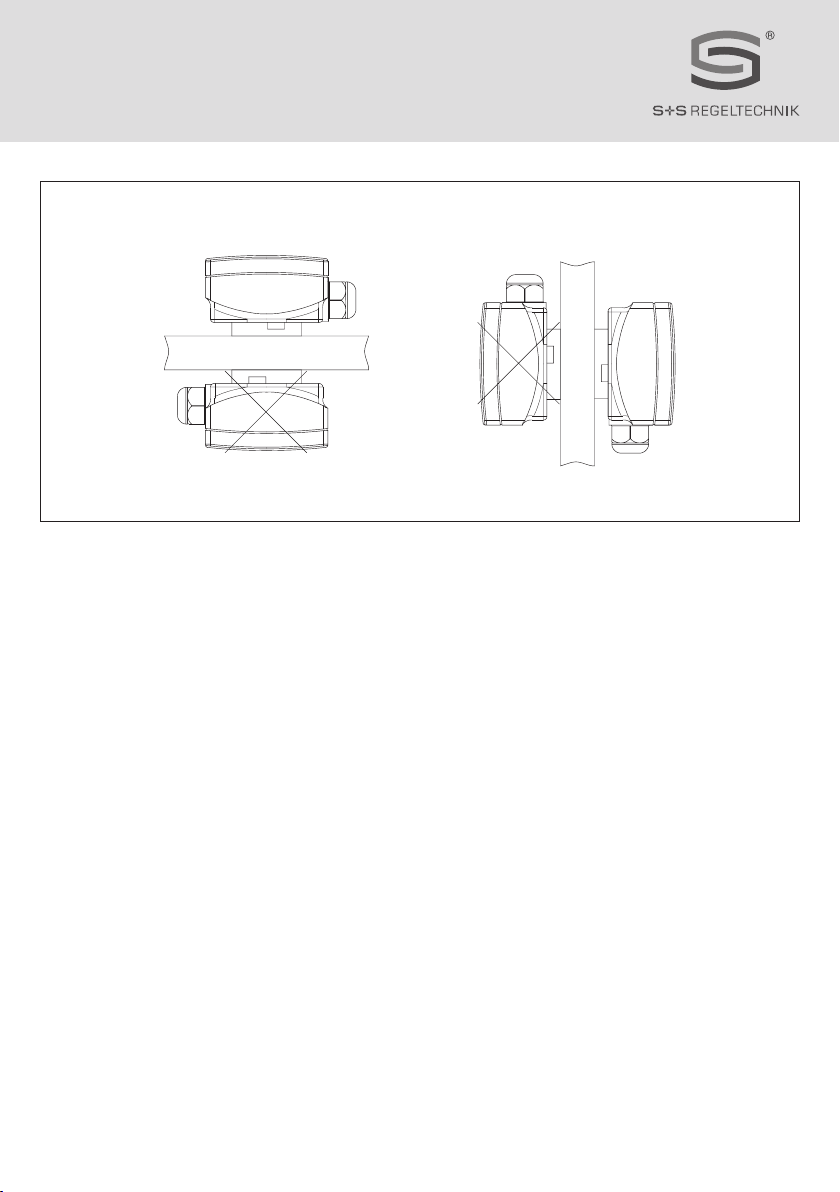
Montageschema KW ⁄ TW
Mounting diagram
Schéma de montage
Схема монтажа
© Copyright by S+S Regeltechnik GmbH
Nachdruck, auch auszugsweise, nur mit Genehmigung von S+S Regeltechnik GmbH gestattet.
Reprints, in part or in total, are only permitted with the approval of S+S Regeltechnik GmbH.
La reproduction des textes même partielle est uniquement autorisée après accord de la société S+S Regeltechnik GmbH.
Перепечатка, в том числе в сокращенном виде, разрешается лишь с согласия S+S Regeltechnik GmbH.
D G F r
Maßzeichnung KW
Dimensional drawing
Plan coté
Габаритный чертеж
HYGRASREG® KW
KW
extern
external
externe
наружный
Sensor
Other manuals for HYGRASREG KW
1
This manual suits for next models
1
Table of contents
Languages:


