spok MAXPage User manual

Installation & Configuration Guide for
MAXPage
Spok, Inc.

Copyright
MAXPage
Document Version 1.0
Copyright 2003-2015 Spok, Inc. All Rights Reserved.
Information in this document is subject to change without notice. The software described in this document is
furnished under one or more Program/Product License Agreements. The software may be used or copied only in
accordance with the terms of those agreements. No part of this publication may be reproduced, stored in a retrieval
system, or transmitted by any means electronic or mechanical, including photocopying and recording for any
purpose without the written permission of Spok, Inc.
Spok, Inc.
10400 Yellow Circle Drive
Suite 100
Eden Prairie, MN 55343
USA
Trademarks
Microsoft and Windows are trademarks of Microsoft Corporation. Other brands and their products are trademarks or
registered trademarks of their respective holders and should be noted as such.

Installation & Configuration Guide for MAXPage Contents
iii
Contents
MAXPage 1
MAXPage........................................................................................................................... 1
Compliance Information..................................................................................................... 1
Safety Information.............................................................................................................. 3
Introduction 5
Introduction ........................................................................................................................ 5
About MAXPage ................................................................................................................ 5
Features............................................................................................................................... 6
Components 7
Components........................................................................................................................ 7
MAXPage Unit................................................................................................................... 8
Top Panel.............................................................................................................. 8
Rear Panel............................................................................................................. 8
Power Adapter.................................................................................................... 10
Quarter Wave Whip Antenna ............................................................................. 10
Assembly & Installation 11
Assembly & Installation ................................................................................................... 11
Preparing for an Assembly and Installation........................................................ 11
Required Components ........................................................................................ 11
Optional Components......................................................................................... 12
Straight-Through Cable...................................................................................... 14
Null Modem Cable............................................................................................. 14
Interference to Telephones, PBXs, and Other Electronic Equipment............................... 16
Powering Up..................................................................................................................... 17
General Operation 18
General Operation............................................................................................................. 18
Navigation .......................................................................................................... 18
Normal Mode.................................................................................................................... 19
Sending a Message ............................................................................................. 19
Using the Telephone (PBX) interface............................................................................... 20
User Mode ........................................................................................................................ 20
Entering User Mode ........................................................................................... 20
Pagers ................................................................................................................. 21
Time ................................................................................................................... 25
Reminders........................................................................................................... 25
Configuration Mode.......................................................................................................... 27
Entering Config Mode........................................................................................ 27
Pagers ................................................................................................................. 27
Ports.................................................................................................................... 32
Using the Telephone (PBX) interface................................................................. 35
Alarm.................................................................................................................. 39
System................................................................................................................ 41
Antitheft Mode (Out of Range) .......................................................................... 41

iv
Contents Installation & Configuration Guide for MAXPage
Password............................................................................................................. 42
Canned Msgs...................................................................................................... 45
License Mode.................................................................................................................... 46
Entering License Mode....................................................................................... 46
Tools Mode....................................................................................................................... 47
Entering Tools Mode.......................................................................................... 47
Changing the MAXPage Frequency, Power Level, & Channel Spacing.......................... 49
Setting up Dial-in TAP to MAXPage from Messenger .................................................... 51
Windows MAXPage Software 53
Windows MAXPage Software.......................................................................................... 53
Windows Versions ............................................................................................. 53
Components........................................................................................................ 53
Installation of Software ...................................................................................... 53
Connecting the Serial Lead................................................................................. 53
Using the MAXPage Windows Software ......................................................................... 54
Connecting to the MAXPage unit..................................................................................... 54
Logging into the Software.................................................................................. 55
Creating a new database in the software............................................................. 56
Opening an Existing Database in the Software .................................................. 56
Uploading Database from the MAXPage Unit to Software................................ 56
Downloading database from software to MAXPage unit................................... 56
Saving Current Database in Software to PC....................................................... 56
Updating Telephone (PBX) Voice Prompts on MAXPage Unit ........................ 57
Logging Out of Software.................................................................................... 57
Disconnecting the MAXPage Connection.......................................................... 57
Configuration of Database................................................................................................ 57
Configuring Pagers............................................................................................. 57
Configuring Groups............................................................................................ 58
Configuring Alarms............................................................................................ 60
Configuring Reminders ...................................................................................... 61
Configuring Common Messages ........................................................................ 61
Configuring Function Keys ................................................................................ 62
Configuring Software Settings ........................................................................... 63
PBX.................................................................................................................... 63
Interface Communications.................................................................................. 64
TAP .................................................................................................................... 65
COMP 1.............................................................................................................. 66
COMP 2.............................................................................................................. 66
SCOPE ............................................................................................................... 66
TEKK ................................................................................................................. 66
Visiplex #1 ......................................................................................................... 66
ESPA.................................................................................................................. 67
Transmitter ......................................................................................................... 67
Patron Pager ....................................................................................................... 68
License ............................................................................................................... 69
Diagnostics ....................................................................................................................... 70
Viewing Pagers................................................................................................... 70
Viewing Groups ................................................................................................. 70
Viewing System Status....................................................................................... 71
Sending Messages............................................................................................................. 71
Recipient Window.............................................................................................. 71
Message Window ............................................................................................... 71
Updating the MAXPage Firmware................................................................................... 73
Technical Specifications................................................................................................... 74
ASCII Character Set........................................................................................... 74
Voice Pager Tone Charts.................................................................................................. 74
Technical Specifications................................................................................................... 75

Installation & Configuration Guide for MAXPage MAXPage
1
MAXPage
MAXPage
Introduction
“Introduction” on page 5 includes information about the MAXPage and its features.
Components
“Components” on page 7 includes information on the top panel, the rear panel, the power adapter, and the quarter
wave whip antenna on the MAXPage unit.
Assembly and Installation
“Assembly & Installation” on page 11 includes information on how to install the MAXPage unit.
General Operation
“General Operation” on page 18 includes general operation information that is required to use the MAXPage unit.
Windows MAXPage Software
“Windows MAXPage Software” on page 53 includes information on the Windows MAXPage software.
Technical Specifications
“Technical Specifications” on page 73 includes technical specifications for the MAXPage system.
Compliance Information
CE (EUROPE)
Spok declares under our sole responsibility that the product Maxpage to which this declaration relates, is in
conformity with the following standards and/or other normative documents.
EN 55022: 1994 +A1: 1995 +A2: 1997
EN 55024: 1998 +A1: 2001 +A2: 2003
EN 60950-1: 2001
We hereby declare that all essential radio test suites have been carried out and that the above named product is in
compliance to all the essential requirements of Directive 1999/5/EC.
The technical documentation relevant to the above equipment can be made available for inspection on application to
Spok.

2
MAXPage Installation & Configuration Guide for MAXPage
ROHS & WEEE
To minimize the environmental impact and take more responsibility for the world in which we live, Spok hereby
confirms that the following product series comply with Directive 2002/95/EC (RoHS) and 2002/96/EC (WEEE) of
the European Parliament.
SAA (AUSTRALIA)
To ensure compliance with ACA Technical Standards, this equipment is labeled with a Telecommunications
Compliance Label. For safety reasons, this equipment should only be connected to compliant telecommunications
equipment in accordance with the manufacturer’s instructions.
FCC (USA)
Part 15
This equipment has been tested and found to comply with FCC Rules and Regulations, Part 15 with the limits of a
Class B digital device, designed to provide reasonable protection against harmful interference. This equipment
generates, uses, and can radiate frequency energy and if not installed and used in accordance with the instructions,
may cause interference harmful to radio communications. On the base of the equipment is a label containing an FCC
Registration Number, if applicable.
Part 68
This equipment complies with Part 68 of the FCC rules. Located on the equipment is a label that contains, among
other information, the FCC registration number and ringer equivalence number (REN.) If requested, this information
must be provided to the telephone company.
The REN is used to determine the quantity of devices which may be connected to the telephone line. Excessive
REN’s on the telephone line may result in the devices not ringing in response to an incoming call. In most, but not
all areas, the sum of the REN’s should not exceed five (5.0). To be certain of the number of devices that may be
connected to the line, as determined by the total REN’s contact the telephone company to determine the maximum
REN for the calling area.
This equipment cannot be used on the telephone company provided coin service. Connection to Party Line Service is
subject to State Tariffs.
If this equipment causes harm to the telephone network, the telephone company notifies you in advance that
temporary discontinuance of service may be required. If advance notice is not practical, the telephone company
notifies the customer as soon as possible. Also, you are advised of your right to file a complaint with the FCC if you
believe it is necessary.
The telephone company may make changes in its facilities, equipment, operations, or procedures that could affect
the operation of the equipment. If this happens, the telephone company provides advance notice in order for you to
make the necessary modifications in order to maintain uninterrupted service.
If trouble is experienced with this equipment, please contact:
Company Name: Spok, 8301 Cypress Plaza Drive, Suite 105, Jacksonville, FL 32256-4416
Tel: +1 904 281 0073, Fax: +1 904 281 0074
If the trouble is causing harm to the telephone network, the telephone company may request you to remove the
equipment from the network until the problem is resolved.
This equipment uses the following USOC jacks: RJ11C

Installation & Configuration Guide for MAXPage MAXPage
3
It is recommended that the customer install an AC surge arrester in the AC outlet to which this device is connected.
This is to avoid damaging the equipment caused by local lightning strikes and other electrical surges.
IC (INDUSTRY CANADA, INDUSTRIE CANADA)
This class B digital apparatus complies with Canadian ICES-003.
Safety Information
Exposure to Radio Frequency Energy
Your MAXPage contains a low power radio transmitter. When it is ON, it receives and transmits radio frequency
(RF) energy.
Your MAXPage is designed to comply with the following national and international standards and guidelines
regarding exposure of human beings to radio frequency electromagnetic energy (EME):
United States Federal Communications Commission, Code of Regulations; 47 CFR part 2 sub-part J
American National Standards Institute (ANSI) / Institute of Electrical and Electronic Engineers (IEEE)
C95. 1-1992
Institute of Electrical and Electronic Engineers (IEEE) C95.1-1999 Edition
National Council on Radiation Protection and Measurements (NCRP) of the United States, Report 86, 1986
International Commission on Non-Ionizing Radiation Protection (ICNIRP) 1998
National Radiological Protection Board of the United Kingdom 1995
Ministry of Health (Canada) Safety Code 6. Limits of Human Exposure to Radiofrequency Electromagnetic
Fields in the Frequency Range from 3 kHz to 300 GHz, 1999
Australian Communications Authority Radio communications (Electromagnetic Radiation-Human
Exposure) Standard 1999
The maximum power density for a VHF or UHF MAXPage set to 4.0 watts power output at a distance of 20cm (7.9
inch) is calculated at 0.79mW / cm². The recommended minimum distance between the MAXPage antenna and the
human body or face is 30cm (12inches).
To assure optimal phone performance and make sure human exposure to radio frequency electromagnetic energy is
within the guidelines set forth in the above standards, always adhere to the procedures outlined below.
Antenna Care
Use only the supplied or an approved replacement antenna. Unauthorized antennas, modifications, or attachments
could damage the device. Do NOT hold the antenna when the device is in use. Holding the antenna affects signal
quality and may cause the MAXPage to operate at a higher power level than needed. Do not use MAXPage with a
damaged antenna. If a damaged antenna comes into contact with your skin, a minor burn can result.
Electromagnetic Interference/Compatibility
Nearly every electronic device is susceptible to electromagnetic interference (EMI) if inadequately shielded,
designed, or otherwise configured for electromagnetic compatibility.

4
MAXPage Installation & Configuration Guide for MAXPage
Operational Warnings
For Vehicles with an Air Bag: When vehicle mounting the MAXPage, do not place the unit in the area over an air
bag or in the air bag deployment area. An air bag inflates with great force. If the MAXPage is placed in the air bag
deployment area and the air bag inflates, the unit may be propelled with great force and cause serious injury to the
vehicle’s occupants.
Potentially Explosive Atmospheres
Do not operate the MAXPage in any area with a potentially explosive atmosphere. Sparks in a potentially explosive
atmosphere can cause an explosion or fire resulting in bodily injury or even death. Areas with potentially explosive
atmospheres include fueling areas such as below decks on boats, fuel or chemical transfer or storage facilities, areas
where the air contains chemicals or particles such as grain, dust, or metal powders, and any other area where you
would normally be advised to turn off your vehicle engine. Areas with potentially explosive atmospheres are often
but not always posted.
Blasting Caps and Areas
To avoid possible interference with blasting operations, do not use the MAXPage near electrical blasting caps, in a
blasting area, or in areas posted: “Turn off two-way radio.” Obey all signs and instructions.

Installation & Configuration Guide for MAXPage Introduction
5
Introduction
Introduction
About MAXPage
The intended use of the MAXPage is to provide an interface with clinical systems to forward information associated
to the particular event to the designated display device(s). For medical, near real-time alarms, the MAXPage is
intended to serve as a parallel, redundant, forwarding mechanism to inform healthcare professionals of particular
medical-related events. The MAXPage does not alter the behavior of the primary medical devices and associated
alarm annunciations. The display device provides a visual, and/or audio, and/or vibrating mechanism upon receipt of

6
Introduction Installation & Configuration Guide for MAXPage
the alert. The MAXPage is intended for use as a secondary alarm. It does not replace the primary alarm. It does not
replace the primary alarm function on the monitor.
MAXPage is an advanced, alpha-numeric paging system that uses the POCSAG protocol. It features a high impact
ABS plastic molded enclosure to ensure long-term durability. MAXPage is a complete, ready to use package, which
is easy to install and operate. One of MAXPage’s primary advantages is that it incorporates a powerful 5 Watt
transmitter, meaning it can provide coverage for small to medium sized sites.
Features
Keypad and LCD Interface
The keypad and LCD provide an interface that allows you to type and send messages, maintain a pager database,
program MAXPage, and perform system tests such as a site survey. The LCD is large, making it easy to read. Both
the keypad and LCD are LED backlit to make it easy to see and use in dark areas. The MAXPage PS2 keyboard can
be connected into the rear of the unit so that alphanumeric characters can be typed in.
Easy Messaging
Messages are sent to on-site pagers by entering the Local ID number of the pager, typing in the message and
pressing the key to send the message. For tone only pagers, simply type in the Pager ID, and press the
key. A number of function keys are available, which enable the user to send canned messages to commonly used
recipients with just the push of a button.
On-Site Paging
MAXPage uses an internal 5 watt transmitter to send instant messages free of charge. Which makes it the ideal
system for any company wanting to contact mobile staff, without amassing a huge, ongoing communications bill.
There are no monthly access fees or per-call charges. The transmitter within the MAXPage provides coverage for
small to medium premises, such as a hotel or hospital. Businesses that benefit from MAXPage include hotels,
motels, schools, churches, retail outlets, health care facilities, manufacturing plants, and mine sites.
User Programmable
MAXPage can store in its EEPROM up to 1000 user programmable pager entries using a local ID of 0 –9999. Each
entry holds the Local ID number of the pager, the format of the paging message (Coaster Pager
/Alpha/Numeric/Tone only/Voice Pager) and the cap code of the pager.
Alarm Monitoring
MAXPage has four dry contact alarm inputs on board. These alarm inputs can be triggered by opening or closing a
circuit (such as by opening or closing a door). Each alarm input may be configured to send a specific message to a
selected pager or group. Alarm messages are broadcast the instant an alarm becomes active or after a programmable
delay time. An alarm may also escalate to another recipient if alarm conditions are not cleared within an acceptable
amount of time.
Version 2011.1.551/SCOPE/ESPA/Visiplex/TEKK Interface
MAXPage has a built in RS232 serial port that is used for programming of the unit or as an optional Version
2011.1.551/SCOPE/ESPA interface that can process paging messages from other systems. Paging messages received
by MAXPage are automatically forwarded to the appropriate on-site pager. TAP, the most commonly used protocol
for communicating paging messages, is sometimes known as PET or IXO. ESPA 4.4.4 is common with European
manufacturers.
Telephony Interface
An optional Telephone interface is built into MAXPage allows you to send messages from any phone on your
Telephone network, or any phone on a PSTN that can access your system. You dial the extension on your PBX or
phone number allotted to the MAXPage. Then, follow the voice prompts to send numeric and even alphanumeric
text messages to any device registered on the MAXPage database. Calls made from PBX phones are free, so it is
convenient and economical to use the Telephone interface.

Installation & Configuration Guide for MAXPage Components
7
Components
Components
Your MAXPage kit contains:
MAXPage Unit
12VDC, 2 Amp regulated Power Adapter
Quarter wave whip antenna with right angle BNC/TNC adapter
CD containing manuals and configuration programs
The following optional components are available. Contact your place of purchase for details.
Two-tone voice pager output interface
Analogue PBX input interface
Alarm input interface
RS232 serial protocol input interface (includes RS232 cable)
PS2 keyboard input interface (includes mini PS2 keyboard)
MAXPage wall mount bracket
8
Components Installation & Configuration Guide for MAXPage
MAXPage Unit
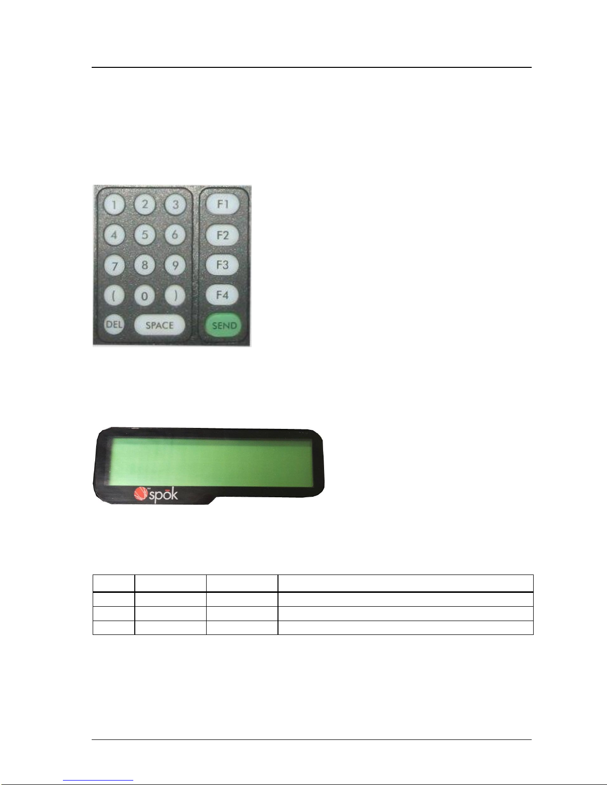
Top Panel
Keypad
The top panel of MAXPage features a 19 key keypad including several useful function keys. The keypad is LED
backlit so that it can be easily seen in dark areas.
LCD
The LCD provides an interface to the software on board MAXPage. It displays 2 lines by 16 alphanumeric
characters. It is also LED backlit for easy night viewing.
LED Status Lights
The LED lights on the front panel indicate the status of the MAXPage unit as follows:
Light
Label
Color
Indicates
Power
Red
MAXPage is turned on
Transmit
Green
MAXPage is transmitting a message to a pager
PBX
Green
MAXPage telephone (PBX) interface is currently active
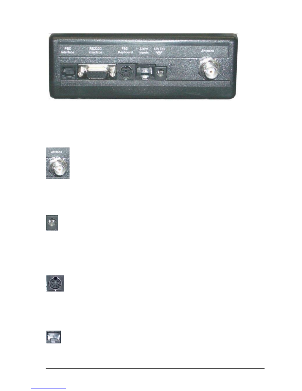
Rear Panel
All connectors the MAXPage are on the rear panel of the unit.
Installation & Configuration Guide for MAXPage Components
9
Transmitter Connector
The whip antenna included with the MAXPage package connects to the internal transmitter via this 50Ω TNC
connector.
12V DC Power Connector
The power adapter included with the MAXPage package supplies power to the unit via this 12VDC connector.
PS2 Keyboard Connector
MAXPage contains (optional) support for a PS2 keyboard. This enables alphanumeric messages to be typed into the
unit.
Alarms Input
Wires connecting (optional) alarm points to MAXPage, interface through this socket. It is an RJ45 connector.
10
Components Installation & Configuration Guide for MAXPage
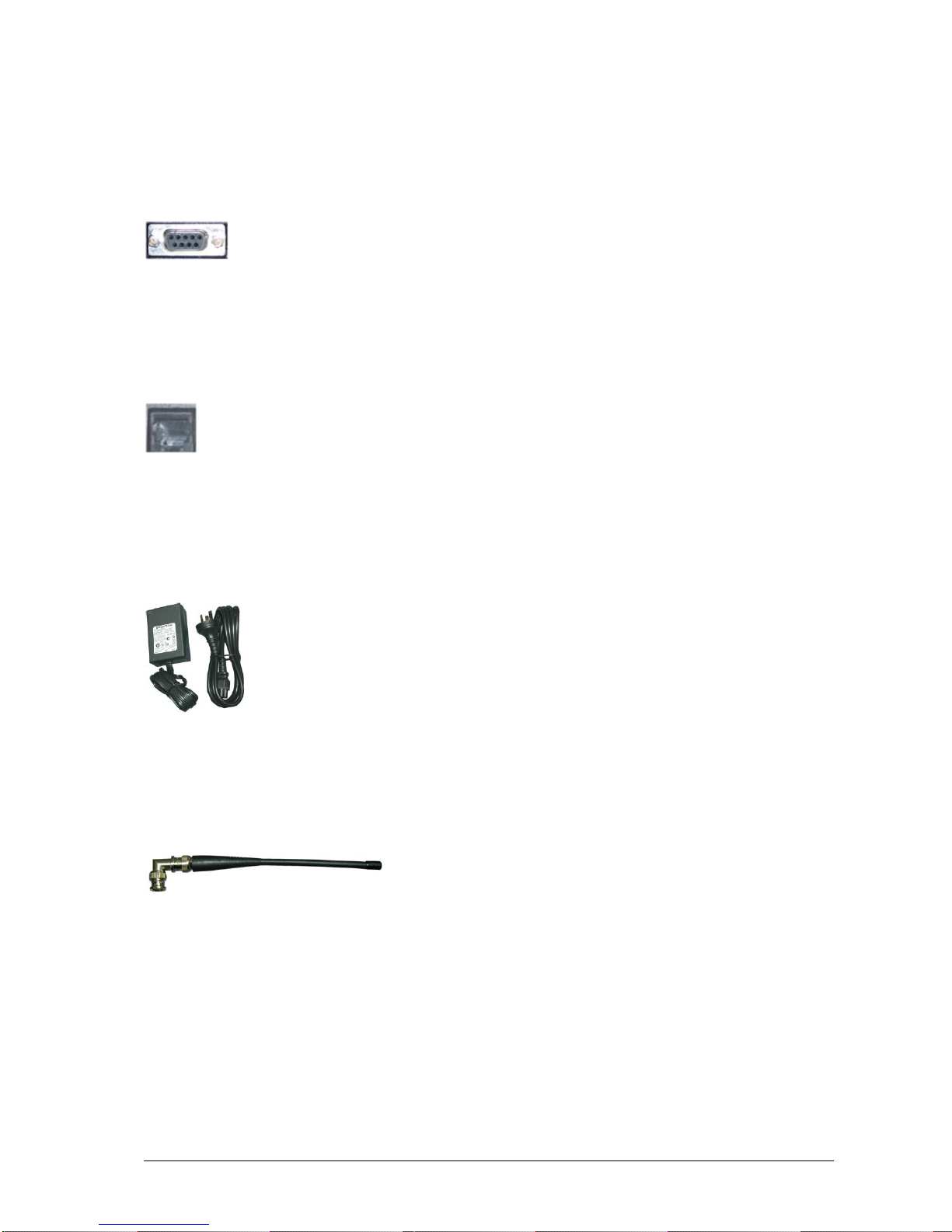
9-Pin RS232 Connector
The DB9F 9-pin RS232 connector may be used to connect MAXPage to (optional) communications systems
outputting TAP, COMP, ESPA, TEKK, VISIPLEX, or SCOPE messages. It is also used to connect to an IBM PC, in
conjunction with the Windows MAXPage software, for settings adjustment and programming of the unit.
PBX Interface
The (optional) Telephone (PBX) interface is used to connect the device to your PBX system or phone system.
Numeric and alphanumeric messages can be sent by following the voice prompts and using the telephone keypad on
the telephone.
Power Adapter
The power adapter included with the MAXPage package converts mains power to the 12volts 2 Amps regulated, as
required by the MAXPage unit.
Quarter Wave Whip Antenna
A standard quarter wave whip antenna is used to transmit the RF signal for the MAXPage unit.

Installation & Configuration Guide for MAXPage Assembly & Installation
11
Assembly & Installation
Assembly & Installation
Preparing for an Assembly and Installation
Before your MAXPage system can be assembled and installed, it must be established if the system is going to use a
narrow band connection or a wide band connection.
After it is established if the system will use a wide band or a narrow band connection, Spok configures the system to
use the desired option.
If, after the system is installed, the chosen option should be switched, Spok should be contacted to re-configure the
system.
If an upgrade is performed on the system, the system automatically uses the existing configuration. If that existing
configuration should be changed, contact Spok. For example, if the system was originally configured to use a narrow
band connection and an upgrade is performed on that system, that system automatically keeps the existing
configuration. Then, in this example, if the system should be configured to use a wide band setting, then Spok must
be contacted to change the configuration.
More specifically, when Spok is contacted for a configuration upgrade, Spok provides a new license key which
changes the setting. After the new license is loaded onto the system, the system must be restarted. After a restart of
the system is performed, the configuration changes are saved to the radio.
Required Components
Antenna
Attach the right angle TNC/BNC adapter to the quarter wave whip antenna. Screw the quarter wave whip antenna
onto the transmitter connector located on the rear panel of the MAXPage unit.

12
Assembly & Installation Installation & Configuration Guide for MAXPage
Power Adapter
Plug the power adapter into mains power. Plug the power adapter into the power connector on the rear panel of
MAXPage.
Optional Components
NOTE: The following components are optional and are not available unless the appropriate license option has been
purchased. Contact your place of purchase for information on how to enable these components if required.
PS2 Keyboard
To connect the PS2 keyboard, plug in the PS2 keyboard connector into the connector labeled PS2 Keyboard.
Alphanumeric input can then be achieved.
Alarm Inputs
To connect alarm inputs into MAXPage you need an RJ45 connector, some CAT5 cable and the appropriate
crimping tool. Alternatively, if you do not have a crimper, you can use or buy a pre-made RJ45-RJ45 cable from any
computer or electronics store and cut one of the ends off if necessary.
The pin-outs for the RJ45 connector are shown below. Each alarm input is a contact-closure type, meaning the alarm
input is triggered by opening or closing the circuit.

Installation & Configuration Guide for MAXPage Assembly & Installation
13
RJ45 Pin
Numbers
Alarm Input
Number
1 + 2
1
3 + 4
2
5 + 6
3
7 + 8
4
NOTE: The four alarm inputs are not isolated from each other –pins 2, 4, 6, and 8 are connected to each other and
share a common ground.
RS232 Serial Port
To interface the MAXPage with a third-party paging system that is outputting a serial protocol, use the female DB9
on the rear of the MAXPage unit.
Front View

14
Assembly & Installation Installation & Configuration Guide for MAXPage
1. The pin-outs for this serial connector on MAXPage are shown below:
Abbreviation
Signal
DB9 Female
TXD
Transmit data
2
RXD
Receive data
3
GND
Ground
5
RTS
Request to send
7
CTS
Clear to send
8
2. When connecting the device to an IBM PC with the MAXPage Windows software installed, a straight
through cable is used. Please see the Windows MAXPage Software section for more information.
3. Depending on the type of third-party paging system you are connecting to, you may need either:
A straight through cable where each pin is wired straight through with TX-TX, RX-RX, and so on.
A null modem crossover cable that has all pins wired straight through except for the transmit and
receive lines, which are crossed (TX-RX and RX-TX).
The section below explains how to make each type of cable if required. Alternatively they can be purchased at a
local computer or electronics store.
Straight-Through Cable
When making a straight-through cable, you need some shielded cable with the appropriate number of conductors
within, a DB9 male plug (for the MAXPage end) and either a DB9/DB25 male/female for the other end, depending
on the equipment it is being connected to.
The table below shows the pin-outs required for correct operation.
Paging Equipment End
MAXPage End
9 pin male/female
25 pin male/female
9 pin male
pin 2
pin 3
pin 2
pin 3
pin 2
pin 3
pin 5
pin 7
pin 5
pin 6
pin 6
pin 6
pin 7
pin 4
pin 7
pin 8
pin 5
pin 8
Null Modem Cable
When making a null modem cable, you need some appropriate cable, a DB9 male plug (for the MAXPage end) and
either a DB9 /DB25 male/female for the other end, depending on the equipment it is being connected to.
The table below shows the pin-outs required for correct operation.
Front View

Installation & Configuration Guide for MAXPage Assembly & Installation
15
Paging Equipment End
MAXPage End
9 pin male/female
25 pin male/female
9 pin male
pin 3
pin 2
pin 2
pin 2
pin 3
pin 3
pin 5
pin 7
pin 5
pin 6
pin 6
pin 6
pin 8
pin 5
pin 7
pin 7
pin 4
pin 8
NOTE: Many serial connections require TX, RX, and GND only. However some devices, do not use all of pins
listed. If you are unsure then use all pins.
NOTE: It is important to note the gender required at each end of a serial cable before acquiring or making a cable.
NOTE: The pin number is usually written next to the pin on the serial connectors themselves in very small writing.
NOTE: Do NOT connect the MAXPage to a printer (or parallel) port output unless you use a parallel to serial
converter. A printer port looks similar to a DB25 serial port but is female.
PBX Interface
If you wish to use the Telephone interface (a.k.a. PBX interface), run a standard phone cable from a spare analogue
PBX extension or standard phone line to the connector shown in the diagram below. Make note of the extension or
phone number MAXPage is connected to. The customers need to be told which extension or phone number to dial in
order to reach the unit.

16
Assembly & Installation Installation & Configuration Guide for MAXPage
Interference to Telephones, PBXs, and Other
Electronic Equipment
The transmitter in MAXPage has a significant power output and when transmitting it may cause interference to other
electronic equipment.
For Audio equipment such as Wired Telephones, Cordless Telephones, Private Branch Exchange (PBX) systems,
Audio / Visual entertainment systems, and Radio Communications equipment, the interference may cause the
following:
An increase in the level of background noise whilst the MAXPage is transmitting
Loss of Audio whilst the MAXPage is transmitting
In general, all electronic equipment may exhibit the following behavior if subjected to interference.
Temporary aberrations in operation, e.g. screen flicker, LCD contrast dimming.
Malfunctions requiring the user to switch off and on the equipment to recover.
Malfunctions requiring the equipment to be serviced.
The following rules apply to the installation of MAXPage in order to address interference to other devices and to the
MAXPage itself.
1. Keep other equipment and their power supplies at least one meter away from the MAXPage’s antenna.
2. Keep the power supply for the MAXPage as far as possible away from the MAXPage’s antenna.
3. Ensure cabling is placed in a neat order and is not in a mess around the back of the MAXPage.
Table of contents
Popular Transmitter manuals by other brands


Hanna Instruments
Hanna Instruments HI 504910 instruction manual

hospicall
hospicall Easywave FU2-UMH manual

Nivus
Nivus NivuFlow Mobile 600 instruction manual

UPM
UPM WT440H owner's manual

Fema Electronica
Fema Electronica CCT-05 user manual

BECKER-Antriebe
BECKER-Antriebe Centronic PLUS EC548 PLUS Assembly and operating instructions