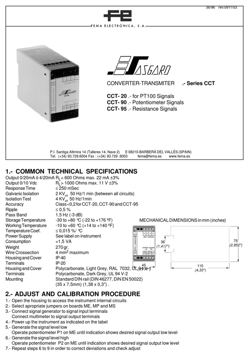
Fema Electronica CCT-05 User manual

Series CCT
Signal Converters with isolation
for frequency signals
IDEAL SOLUTION to convert a wide range of analogue signals (process,
temperatures, current, frequencies...) to standard 10Vdc or 20mA process
signals, for further retransmission to a remote data acquisition system or PLC’s.
The galvanic isolation offered by the CCT instruments between the signal circuit
and the remote equipment, reduces to a minimum any eventual problem related
to ground loops between different circuits.
CCT-05 for frequency signals up to 40 KHz
Signal
Converters
Isolated
FEMA ELECTRÓNICA
USER’S MANUAL
(1253R03)

FEMA ELECTRÓNICA - Page 2
User’s Manual CCT-05
Model CCT-05
Converters for frequency signals
Signal converters for frequency signals. Selection of input and output ranges with internal
jumpers and potentiometers. Galvanic isolation between input, output and power circuits.
Technical Data
Accuracy CCT-05 Class <0.2
Ripple <0,5 %
Temperature coefcient <0,015 %/ °C
Pass band 1.5 Hz (-3 dB a 3Hz)
Response time <250 mSec.
Output in mA 0/20 mA / 4/20 mA, ...
RL< 600 Ohms
max. 22mA
active output loop
Output in Vdc 0/10 Vdc, 0/1 Vdc, ...
RL> 1000 Ohms
max. 11Vdc
Isolation 2 KVeff / 50Hz / 1 min
(tested at 4 KVeff)
Isolated circuits input / output / power
Weight 270 gr.
Wire section 4mm2 maximum
Housing IP protection IP40
Terminals IP protection IP20
Housing material polycarbonate, light grey
RAL 7032, UL 94 V-1
Mounting standard DIN rail (DIN 46277,
DIN EN 50022) (35 x 7,5mm) (1,38 x 0,3”)
Terminals Polycarbonate,UL 94 V-2
Consumption <3W
Storage temperature -30 to +80 °C
Working temperature -10 to +60 °C
Power wires
1 to 2.5mm2 (AWG17 to AWG14)
Order Reference
CCT 05
Model
-0
Power
-0 (230 Vac)
-1 (115 Vac)
-2 (24 Vac)
-3 (48 Vac)
-6 (24Vdc isolated)
-0/1 KHz
Input
0/40 KHz
0/1 KHz
0/700 Hz
0/100 Hz
...
-4/20mA
Output
4/20mA
0/10Vdc
...
=
With a at screwdriver, force the front cover and walls towards
Aand B, until xations ‘3’ are free. Take the instrument from
points ‘2’ ‚ and extract it pulling towards C:
ME - Signal Input Module
MS - Signal Output Module
MA - Power Module
MP - Personalized Module
B
ME MS
MA
MP
C
A
Access to internal circuits
Remove front cover to access the internal circuits,
reduces the protection to the operator (dangerous
voltages may be accessible). The operation must
be performed by qualied personnel only.
45
(1,771”)
110
(4,33”)
36
(1,417”)
75
(2,952”)
Mechanical dimensions mm (inch)

User’s Manual CCT-05
FEMA ELECTRÓNICA - Page 3
Frequency Signals
up to 40 Khz
CCT-05
Signal converter for frequency signals. Internal jumper selection for 5 different ranges of measure, ranging from 0/40 Hz up
to 0/40 Khz. Accepts PNP, NPN, Namur and sinusoidal signal types. Provides two types of excitation voltages for transduc-
ers, 24 Vdc for PNP and NPN types, and 8,2 Vdc for NAMUR types.
Congure the desired frequency input range and sensor type by selecting the appropriate jumpers on «MP» module, as
shown on the tables below:
INPUT RANGE SELECTION
MP
3 2 1
PT2
7
8
9
10
PT1
4 5 6
PT1 - Fine Gain Adjustment. (Additional P2 potentiom-
eter on input module ME).
PT2 - TriggerAdjustment. Is the voltage level at which the
input signal is recognized to be as logic ‘1’ or logic ‘0’. It
can be set empirically operating on potentiometer PT2.
0/22.5-40 KHz 1,6
0/12.5-22.5 KHz 1,5
0/7-12.5 KHz 1,4
0/4-7 KHz 1
0/2.25-4 KHz 2,6
0/1.25-2.25 KHz 2,5
0/700-1250 Hz 2,4
0/400-700 Hz 2
0/225-400 Hz 3,6
0/125-225 Hz 3,5
0/70-125 Hz 3,4
0/40-70 Hz 3
SENSOR JUMPER CONNECTIONS
«MP»
Push-Pull (3 wires) 10 3,5,6
NPN-PNP (3 wires) 10 3,5,6
NPN (open collector) 10,7 5,6
PNP (open collector) 10,8 5,6
NAMUR 10,9 4,5
Vac<100V 10 5,6
Vac>100V --- 5,6
RANGE JUMPER
«MP»
RANGE JUMPER
«MP»
CONNECTIONS
Power
Fuse Switch
Sinusoidal
-
+
+
-
NPN, PNP
-
+
Namur -
+
Voltage
output
Current
output
+
-
-
+
The CCT converters allow different power modules in AC and DC. The instrument does not have internal protection fuse.
Following is a recommendation on value and type of fuse for each power module available.
Fuses
Ref. Power Fuse Recommended
«0» 230 Vac 50/60 Hz 50 mA Time Lag
«1» 115 Vac 50/60 Hz 100 mA Time Lag
«2» 24 Vac 50/60 Hz 300 mA Time Lag
«3» 48 Vac 50/60 Hz 150 mA Time Lag
«6» 24 Vdc 300 mA Fast Fuse

FEMA ELECTRÓNICA - Page 4
User’s Manual CCT-05
CE Declaration of conformity
1.- Open the housing to access the instrument internal circuits
2.- Select jumpers on boards «ME», «MP» and «MS»
3.- Connect signal generator to signal input terminals
4.- Connect multimeter to signal output terminals
5.- Power up the instrument as indicated on the label
6.- Generate the low signal level and operate potentiometer
P1 on «ME» until the multimeter shows the desired signal
output
7.- Generate the high signal level and operate potentiometer
P2 on «ME» until the multimeter shows the desired signal
output
8.- Repeat steps 6 to 7 in order to correct deviations and
check the adjust
The CCT has available outputs in voltage and current. Only
one of the outputs can be active. Additional to the standard
0/10 Vdc and 4/20mA outputs, it is possible to recongure
the instrument to any of the outputs shown in the table below.
Other mA outputs
(Resistances in Ohms)
OUTPUT R18 R24 R25
0/5mA - - - 100 - - -
0/10mA - - - 49,9 - - -
1/5mA 100K 124 - - -
0/20mA - - - - - - 24,9
Other Vdc outputs
(Resistances in KOhms)
OUTPUT R29 R30 R31 R32
±10Vdc 49,9 - - - 200 - - -
0/1Vdc - - - - - - 11 100
0/5Vdc - - - - - - 100 100
1/5Vdc - - - 100 66,5 100
Jumpers E and F .- Closed in 4/20 mA output. Open for other outputs
Note .- The symbol «- - -» means «NOT installed»
Placed on the «ME» module are the potentiometers and
jumpers for Zero and Gain adjustment.
Jumper 1 - Closed for Gross Positive Offset
Jumper 2 - Closed for Gross Negative Offset
Jumper A - Closed for Fine Negative Offset
Jumper B - Closed for Maximum GAIN
Jumper C - Closed for Middle GAIN
Jumper B and C - Open for Minimum GAIN
P1 .- Zero Adjust Potentiometer
P2 .- Gain Adjust Potentiometer
Output signal module (MS)
Readjustment procedure
Input signal module (ME)
E F MS
R30
R29
R18
R31
R32
R24
R25
ABC
ME
P1 P2
1
2
Manufacturer FEMA ELECTRÓNICA, S.A.
Altimira 14 - Pol. Ind. Santiga
E08210 - Barberà del Vallès
BARCELONA - SPAIN
Products CCT-01, 04, 05, 06, 08, 20, 22, 23, 24, 25, 26, 27, 32, 55I, 55V, 80, 90, 95
The manufacturer declares that the instruments indicated comply
with the directives and rules indicated below.
Electromagnetic compatibility directive 2014/30/EU
Low voltage directive 2014/35/EU
ROHS directive 2015/863/EU
WEEE directive 2012/19/EU
Security rules EN-61010-1
Instrument Fixed, Permanently connected
Pollution degree 1 and 2 (without condensation)
Isolation Double (
exception for CCT-01 and CCT-08, when
measuring between >300Vac/dc and 600Vac/dc, isolation is BASIC)
Overvoltage category 2
Electromagnetic compatibility rules EN-61326-1
EM environment
Industrial
CISPR 11 Instrument Class A & Class B Group 1
For a detailed declaration see document:
www.fema.es/docs/5232_CE-Declaration_CCT_en.pdf
Barberà del Vallès, October 2020
Xavier Juncà - Product Manager
According to directive 2012/19/EU, electronic
equipment must be recycled in a selective and
controlled way at the end of its useful life.
This instrument has been designed and veried conforming to
the 61010-1 CE Security Regulation, for industrial applications.
Installation of this instrument must be performed by qualied
personnel only. This manual contains the appropriate information
for the installation. Using the instrument in ways not specied
by the manufacturer may lead to a reduction of the specied
protection level. Disconnect the instrument from all external
circuits before starting any maintenance and / or installation
action.
The instrument does not have a general switch and will start
operation as soon as power is connected. The instrument
does not have protection fuse, the fuse must be added during
installation.
The instrument is designed to be DIN rail mounted, inside a
cabinet, protected from direct impacts. An appropriate ventilation
of the instrument must be assured. Do not expose the instrument
to excess of humidity. Maintain clean by using a humid rag and
do NOT use abrasive products such as alcohols, solvents, etc.
General recommendations for electrical installations apply, and
for proper functionality we recommend : if possible, install the
instrument far from electrical noise or magnetic eld generators
such as power relays, electrical motors, speed variators, ... If
possible, do not install along the same conduits power cables
(power, motor controllers, electrovalves, ...) together with
signal and/or control cables. Before proceeding to the power
connection, verify that the voltage level available matches the
power levels indicated in the label on the instrument. In case of
re, disconnect the instrument from the power line, re alarm
according to local rules, disconnect the air conditioning, attack
re with carbonic snow, never with water.
Precautions on installation
This manual suits for next models
2
Other Fema Electronica Transmitter manuals
