Sponsler SP714-S2i User manual
Liquid ControLs Group An IDEX Fluid & Metering Business
Sponsler SP714-S2i
Pulse Amplier
Installation & Parts
Operation: EM700-10

INTRODUCTION
Safety Procedures.................................................... 3
General Information ................................................. 3
Dimensions .............................................................. 4
Specications ........................................................... 4
Regulatory Compliance Tag Markings...................... 6
TABLE OF CONTENTS
INSTALLATION
Installation Overview ................................................ 7
Wiring ....................................................................... 7
Settings ................................................................... 11
Diagnostics.............................................................. 11
Maintenance............................................................ 11
This manual provides warnings and procedures that are intended to inform the owner
and/or operator of the hazards present when using the Liquid Controls Meter on LP-
Gas and other products. The reading of these warnings and the avoidance of such
hazards is strictly in the hands of the owner-operators of the equipment. Neglect of
that responsibility is not within the control of the manufacturer.
NOTICE
The most current English versions of all Liquid Controls publications are available on our web site, www.lcmeter.com. It is the
responsibility of the local distributor to provide the most current version of LC manuals, instructions, and specication sheets in
the required language of the country, or the language of the end user to which the products are shipping. If there are questions
about the language of any LC manuals, instructions, or specication sheets, please contact your local distributor.
Publication Updates and Translations
2

SAFETY PROCEDURES AND GENERAL INFORMATION
!WARNING
North America - Installations must be in full accordance with the National Electrical Code (US) or the Canadian
Electrical Code respectively to maintain the hazardous location ratings on the product.
Outside of North America - Installations must be in full accordance with EN 60079-14 to maintain the hazardous
location ratings on the product. Use Ex d certied cable glands only. For ambient temperatures above 70ºC, use eld
wiring rated 20ºC above the maximum ambient temperature.
WARNING: Explosion Hazard -
Substitution of components may impair suitability for hazardous area applications.
WARNING: Explosion Hazard -
When in hazardous locations, turn power OFF before replacing or wiring modules.
WARNING: Explosion Hazard -
Do NOT disconnect equipment unless power has been switched OFF or the area is known to be Non-Hazardous.
Observe National and
Local Codes
!WARNING
Be Prepared
• Before using this product, read and understand the instructions.
• All work must be performed by qualied personnel trained in the proper application, installation, and maintenance of
equipment and/or systems in accordance with all applicable codes and ordinances.
• When handling electronic components and boards, always use proper Electrostatic Discharge (ESD) equipment and
follow the proper procedures
• Make sure that all necessary safety precautions have been taken.
• Provide for proper ventilation, temperature control, re prevention, evacuation, and re management.
• Provide easy access to the appropriate re extinguishers for your product.
• Consult with your local re department, state, and local codes to ensure adequate preparation.
• Read this manual as well as all the literature provided in your owner’s packet.
• Save these instructions for future reference.
• Failure to follow the instructions set forth in this publication could result in property damage, personal injury, or death
from re and/or explosion, or other hazards that may be associated with this type of equipment.
General Information
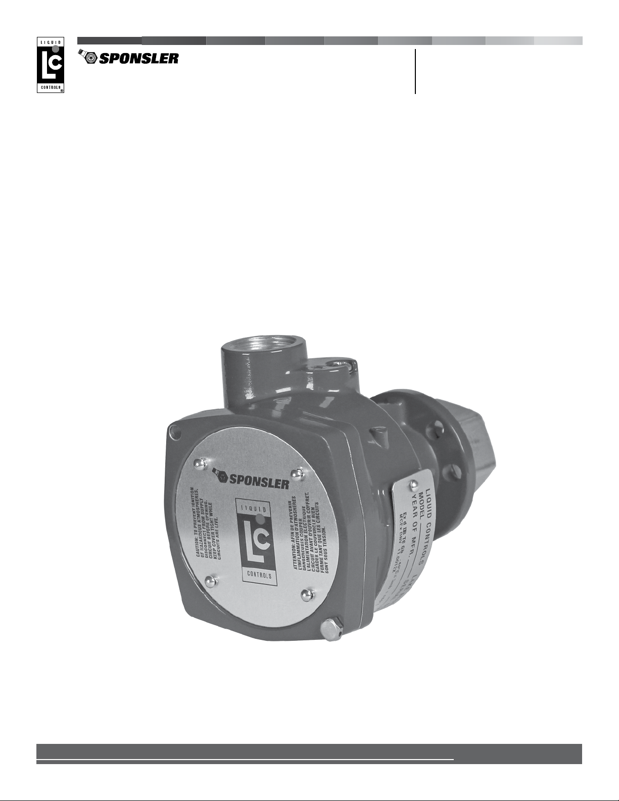
The SP714-S2i is a meter-mounted pulse amplier that amplies and conditions low amplitude signals, typically
produced by the magnetic pickup coil of a Sponsler turbine owmeter. The SP714-S2i transforms the low power input
signal from the pickup coil into square-wave output signals with enough energy to travel a greater distance and be
detected reliably by the electronic device, such as a ow computer or an electronic register.
The SP714-S2i includes an input signal sensitivity adjustment (R1) that permits the SP714-S2i to discriminate
between an input signal and noise by increasing or decreasing the input signal amplitude necessary to be processed
as a valid signal. This, in conjunction with being directly mounted onto the turbine ow meter, allows the SP714-S2i to
operate effectively in noisy environments.
The SP714-S2i also includes diagnostic tools. The diagnostic test oscillator (SW2) enables the operator to verify the
ampliers operation without a signal source. The green LED (D1)indicates the power supply status. The red LED (D2)
indicates the signal frequency status.
In order to maintain IECEx compliance, the SP714-S2i is connected to the turbine owmeter boss. The
turbine meter and SP714-S2i assembly is pressure tested at the factory, then shipped as an assembly.
SP714-S2i and Sponsler Turbine Flowmeter Shipped as Assembly
3
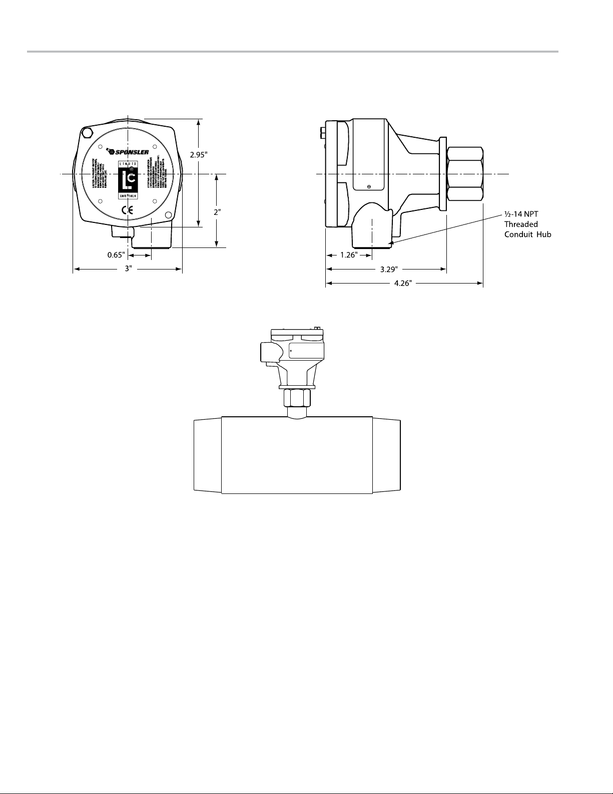
DIMENSIONS AND SPECIFICATIONS
Weight
• 1.2 lbs (0.54 kg)
Materials of Construction
Housing
• Aluminum Alloy ADC12
• Powder Coat: Corro-Coat PE 74-141 Polyester
Adapter (to turbine meter boss)
• Stainless Steel
Cable Entry
• ½"-14 NPT
Temperature Range
Operating
• -40 to 176 °F (-40 to 80 °C)
Storage
• -76 to 257 °F (-60 to 125 °C)
Input Voltage
• 6-28 VDC; 83 mA maximum @ 24 VDC
• Protected against polarity reversal
Signal Input
Frequency
• 2 kHz maximum over operating temperature in all modes
Amplitude
• 10 mV p-p minimum sine or square wave
Impedance
• 50 KΩ
Sensitivity Field
• Adjustable by potentiometer (R1)
Output Signal Characteristics
See following page.
FRONT SIDE
SP714-S2i
AND TURBINE
FLOWMETER
Dimensions
4
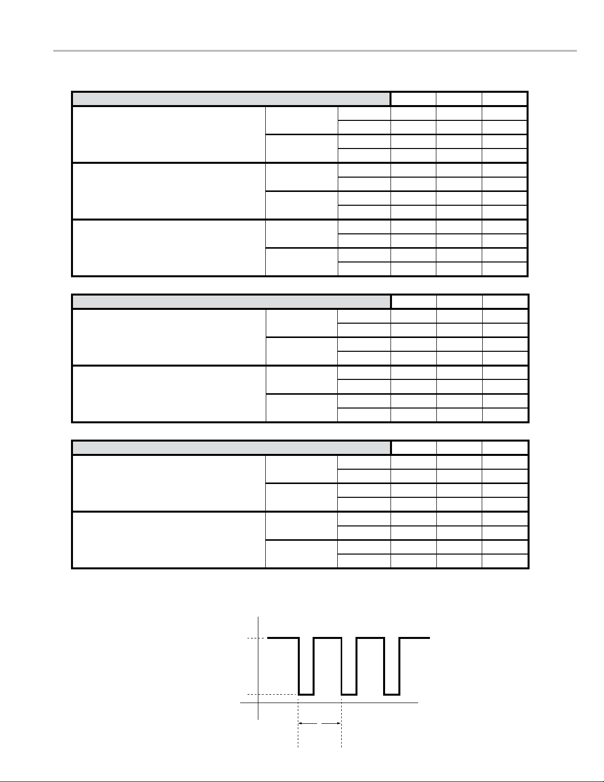
SPECIFICATIONS
MiniMuM MaxiMuM units
DC power supply voltage: 12 V
Total System Resistance: 130 Ω± 25 Ω
Output Voltage Logic HIGH 9 VDC
Logic LOW 5 VDC
Output Current Logic HIGH 12 mA DC
Logic LOW 83 mA DC
DC power supply voltage: 24 V
Total System Resistance: 250 to 400 Ω
Output Voltage Logic HIGH 18 VDC
Logic LOW 5 VDC
Output Current Logic HIGH 15 mA DC
Logic LOW 83 mA DC
DC power supply voltage: 28 V
Total System Resistance: 360 Ω± 60 Ω
Output Voltage Logic HIGH 21 VDC
Logic LOW 5 VDC
Output Current Logic HIGH 15 mA DC
Logic LOW 83 mA DC
*Depends on power supply voltage and total system resistance (Load impedance + signal cable resistance)
MiniMuM MaxiMuM units
DC power supply voltage: Vcc: 4 – 28 VDC
Total System Resistance: 500 Ωminimum @ 28 VDC
Output Voltage Logic HIGH Vcc – 1* VDC
Logic LOW 0.25 VDC
Output Current Logic HIGH ~8 to 60 mA DC
Logic LOW 8 mA DC
DC power supply voltage: Vcc: 4 – 28 VDC
Total System Resistance: 10 kΩ(Example)
Output Voltage Logic HIGH Vcc – 0.60* VDC
Logic LOW 0.25 VDC
Output Current Logic HIGH ~8 to 11 mA DC
Logic LOW 8 mA DC
*Depends on DC power supply voltage value
MiniMuM MaxiMuM units
DC power supply voltage: Vcc: 4 – 28 VDC
Total System Resistance: 500 Ωminimum @ 28 VDC
Output Voltage Logic HIGH Vcc – 0.5* VDC
Logic LOW 0.5 VDC
Output Current Logic HIGH 7 mA DC
Logic LOW 8 to 60 mA DC
DC power supply voltage: Vcc: 4 – 28 VDC
Total System Resistance: 10 kΩ(Example)
Output Voltage Logic HIGH Vcc – 1* VDC
Logic LOW 0.5 VDC
Output Current Logic HIGH 7 mA DC
Logic LOW 8 to 11 mA DC
*Depends on external DC power supply voltage value
TYPICAL
SIGNAL
OUTPUT
WAVEFORM
Maximum
Voltage
Time
Minimum
One
Cycle
0
5

REGULATORY COMPLIANCE TAG
Explosive Atmospheres symbol
IECEX DNV 11.0012X
This equipment has been found to comply with the Certication Scheme for Explosive Atmospheres of INTERNATIONAL
ELECTROTECHNICAL COMMISSION (IECEx). Evaluation was made in 2013 by Det Norske Veritas (DNV) to IECEx scheme
with a certicate number IECEx DNV 11.0012X, where X represents the following Special Conditions for Safe Use: 1) Only Ex
d certied cable glands are to be used; and 2) For ambient temperatures above 70 °C, use eld wiring suitable for 20°C above
maximum ambient temperature.
II
Suitable for use in surface (not mine) installations.
2 G
High level of protection is provided against ammable gases, vapors, or liquids, which may exist during normal operation.
Ex d
Explosion protection is provided by a ameproof enclosure.
IIB
Gas group, which includes ethylene, propane, and methane.
T6:
Temperature class for surface temperature limitations. T6 is ≤ 85ºC
Gb
Equipment group per IEC 60079-0:2007.
amb
Safe limits of ambient temperature.
IP66
Ingress protection: dust tight and protected against powerful water jetting.
Consult factory for current compliance status.
6

INSTALLATION OVERVIEW
In order to maintain IECEx compliance, the SP714-S2i is shipped as part of an assembly with a Sponsler turbine
owmeter. A complete installation of the owmeter and pulse amplier assembly includes the physical installation of
the owmeter and the electrical installation of the SP714-S2i. Guidelines for the physical installation of the owmeter
can be found in the Sponsler turbine owmeter manual. Instructions for the electronic installation of the SP714-S2i are
included in this manual.
1. Install Sponsler turbine owmeter (with SP714-S2i) into system piping. Sponsler Turbine Flowmeter Installation Manual
2. Wire the SP714-S2i to a pulse acquisition device and set the S1 switches to the preferred output signal characteristics. Page 7
3. Perform eld test and adjust the input signal sensitivity (if necessary). Page 11
Use the proper cable glands, conduit connectors, cables,
conduit, and installation procedures when wiring the SP714-S2i.
Installations must be in full accordance with national and local
codes to maintain the hazardous location ratings on the product.
Observe National and Local Codes
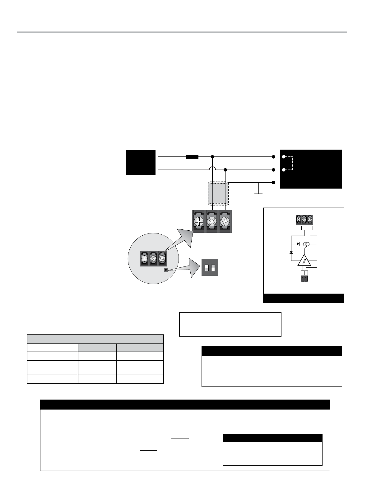
WIRING THE OUTPUT SIGNAL CONFIGURATIONS
The SP714-S2i can be set to one of three congurations: 2-wire Standard, 3-wire TTL Sourcing, and 3-wire Open
Collector. The 2-wire Standard conguration translates the output signal from the turbine owmeter’s pickup coil into
a current value. 2-wire connections are effective transmitting the signal over long distances. The 3-wire TTL Sourcing
conguration translates the output signal from the turbine owmeter’s pickup coil into a voltage value. The output
of the 3-wire TTL Sourcing conguration is driven either positive or negative internally. The 3-wire Open Collector
conguration translates the output signal from the turbine owmeter’s pickup coil into a voltage value. The output is
driven by an “Open Collector” transistor.
Each conguration requires a specic positioning of the two S1 switches, specic
wiring connections (to the power supply and the pulse acquistition device), and a
resistor(s) spliced into the +V leg from the power supply (optional for the 3-wire TTL
Sourcing conguration).
The best conguration for your application is determined by the specications of the
pulse acquistion device (typically a ow computer or electronic register) receiving
the SP714-S2i signal and the electrical characteristics of the application.
SW1
S1
JU4
D1 D2
GND
TB2
S2
R1
TB1
ONON
12
GND
1
S1 Switches
• 18 AWG stranded wire in shielded cable, UL Listed For
ambient temperatures above 70°C, use eld wiring suitable for 20°C
above maximum ambient temperature.
• ½-14 NPT cable glands Use Ex d certied cable glands only.
• Connectors for pulse acquisition device or DC power supply
See “Observe National and Local Codes” on this page.
• PTFE tape or pipe sealant
7
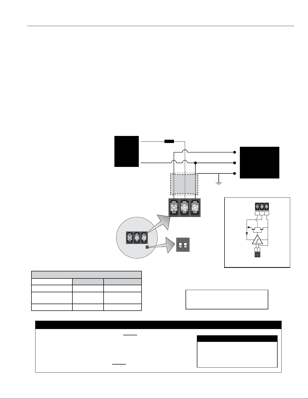
2-WIRE STANDARD
The 2-wire Standard conguration translates the output signal from the turbine owmeter’s pickup coil into a current
value. The 2-wire Standard conguration produces an output signal using a resistor to convert the electrical current
variations into voltages. In this conguration, the power supply travels on the signal wire. 2-wire connections are
effective transmitting the signal over long distances.
1. Remove the SP714-S2i housing cover.
2. Pull the SP714-S2i board from the housing for access to the TB1 terminal block and the S1 switches.
3. Attach proper cable glands and/or conduit connectors to the SP714-S2i, the pulse acquisition device, and DC power supply.
4. Run the wires (through proper conduit) between the SP714-S2i, the pulse acquisition device, and DC power supply.
5. Set the rst S1 switch to the
ON position and the second S1
switch to the OFF position.
6. Splice the resistor onto the +V
leg from the DC power supply.
The value of the resistor can be
determined using the information below.
7. Wire the SP714-S2i to the pulse
acquisition device and DC
power supply as indicated in the
schematic.
8. If necessary, adjust the input
signal sensitivity (R1), activate
the diagnostic test oscsillator
(SW2), and/or check the
diagnostic operational LEDs (D1
& D2). See page 11.
9. Coil the wires underneath the
CPU board and place the board
inside the housing, ensuring
the wires are not pinched, and
replace the housing cover.
2-WIRE STANDARD WIRING
S1
ONON
12
GND
1
Signal+V
0V Signal Ground
Cable Shield
Resistor (RP)
Two
Conductor
Shielded
Cable
Position 1 - ON
Position 2 - OFF
ONON
12
Electronic Register
or
Flow Computer
Zinput resistance
DC Power
Supply
Chassis GND
S1
TB1
INTERNAL OPERATING PRINCIPLE
3 2 1
2 1
TB2
Pickup Coil Signal
TB1
3 2 1
Connect Chassis GNDs at pulse acquisition device only
If the total system resistance in a 2-wire standard
conguration exceeds the recommended value, the
preamplier may function irregularly as a result of
insufcient supply voltage to the terminals.
!CAUTION !
SP714-S2i Connections
Pulse Acquisition Device
Sponsler IT 400 TB2 (1) TB2 (2)
LectroCount
LCR-II/LCR 600 J8 (33) J8 (37)
Toptech MultiLoad TB2B (V+ any) TB2B (V COM any)
Maximum Cable Length: 380 m (1200’)
Minimum Wire Gauge: 0.75 mm2(18 AWG)
Maximum cable wire resistance must be less than 30 Ω Rcable = Rw1+ Rw2 (both wires in cable)
Total system resistance with +24 VDC power supply must be between 250 and 400 Ω Rsystem = Rcable + RP
Maximum System Current Imax = 90 mA Imax =
Resistor (RP) Power Dissipation PRd =
Resistor Value - 2-wire Standard
(Vdc)2
Rp
Vdc
Rsystem
24 VDC Power Supply: Rp = 330 Ω, 2 W
12 VDC Power Supply: Rp = 150 Ω, 2 W
Recommended Resistor Value (Rp)
8
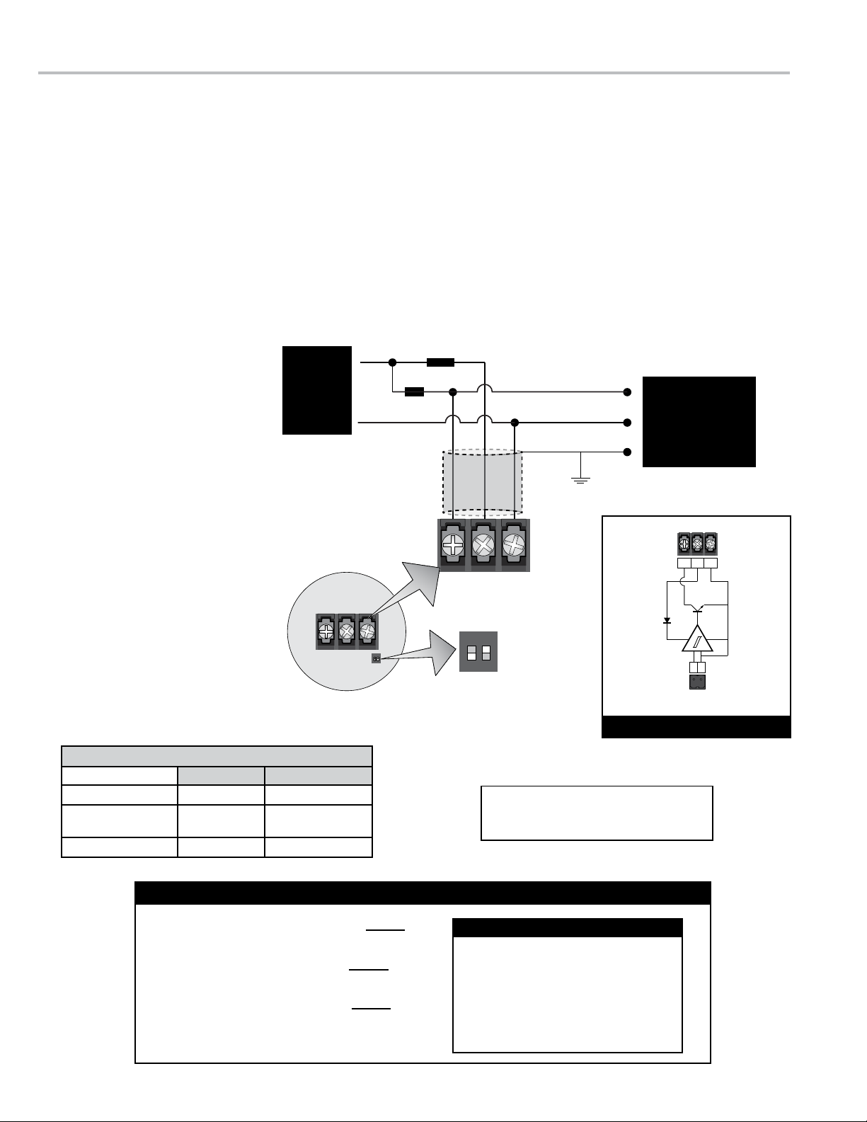
The 3-wire TTL Sourcing conguration translates the output signal from the turbine owmeter’s pickup coil into a
voltage value. The output of the 3-wire TTL Sourcing conguration is driven either positive or negative internally. Note
that the name “TTL” is misleading because the output switches from 0V to +Vs, not 0V to +5V as the TTL standard
indicates. In the SP714-S2i, “TTL” indicates that the output is driven in both the positive and zero volt cases. A pull-
up or pull-down resistor is optional in the 3-wire TTL Sourcing conguration; however, a resistor can be installed to
prevent damage from faults.
1. Remove the SP714-S2i housing cover.
2. Pull the SP714-S2i board from the housing for access to the TB1 terminal block and the S1 switches.
3. Attach proper cable glands and/or conduit connectors to the SP714-S2i, the pulse acquisition device, and DC power supply.
4. Run the wires (through proper conduit) between the SP714-S2i, the pulse acquisition device, and DC power supply.
5. Set the rst S1 switch to the ON position and the second S1 switch to the ON position.
6. Splice the resistor onto the +V
leg from the DC power supply.
This step is optional. The value of the
resistor can be determined using the
information below.
7. Wire the SP714-S2i to the pulse
acquisition device and DC
power supply as indicated in the
schematic.
8. If necessary, adjust the input
signal sensitivity (R1), activate the
diagnostic test oscsillator (SW2),
and/or check the diagnostic
operational LEDs (D1 & D2). See
page 11.
9. Coil the wires underneath the
CPU board and place the board
inside the housing, ensuring
the wires are not pinched, and
replace the housing cover.
S1
ONON
12
GND
1
3 2 1
Signal
+V
0V
S1
Signal Ground
Position 1 - ON
Position 2 - ON
ONON
12
DC Power
Supply
Resistor (RP)
Electronic Register
or
Flow Computer
Chassis GND
Cable Shield
3 2 1
2 1
TB2
Pickup Coil Signal
TB1
INTERNAL OPERATING PRINCIPLE
optional
Three
Conductor
Shielded
Cable Connect Chassis GNDs at pulse acquisition device only
SP714-S2i Connections
Pulse Acquisition Device
Sponsler IT 400 TB2 (1) TB2 (2)
LectroCount
LCR-II/LCR 600 J8 (33) J8 (37)
Toptech MultiLoad TB2B (V+ any) TB2B (V COM any)
Maximum Cable Length: 1000 m (3280’)
Minimum Wire Gauge: 0.75 mm2(18 AWG)
Limit total system current to 50 mA Imax =
For 24 VDC operation pulse acquisition device impedance must be at least 1200 Ω
For 5 VDC operation pulse acquisition device impedance must be at least 250 Ω
Resistor (RP)Power Dissipation P =
Resistor Value - 3-wire TTL Sourcing
24 VDC Power Supply: Rp = 680 Ω, 1 W
12 VDC Power Supply: Rp = 330 Ω, 1 W
5 VDC Power Supply: Rp = 12 Ω, 2.5 W
Recommended Resistor Value (Rp)
Vdc
RP
(V)2
RP
9
The 3-wire Open Collector conguration translates the output signal from the turbine owmeter’s pickup coil into a
voltage value. The output is driven by an “Open Collector” transistor. A resistor is required to “pull-up” the voltage
when the transistor is ‘off’.
1. Remove the SP714-S2i housing cover.
2. Pull the SP714-S2i board from the housing for access to the TB1 terminal block and the S1 switches.
3. Attach proper cable glands and/or conduit connectors to the SP714-S2i, the pulse acquisition device, and DC power supply.
4. Run the wires (through proper conduit) between the SP714-S2i, the pulse acquisition device, and DC power supply.
5. Set the rst S1 switch to the OFF position and the second S1 switch to the ON position.
6. Splice the resistors between
the +V leg from the DC power
supply and the signal input
leg to the pulse acquisition
device. The value of the resistor can
be determined using the information
below.
7. Wire the SP714-S2i to the
pulse acquisition device and
DC power supply as indicated
in the schematic.
8. If necessary, adjust the input
signal sensitivity (R1), activate
the diagnostic test oscsillator
(SW2), and/or check the
diagnostic operational LEDs
(D1 & D2). See page 11.
9. Coil the wires underneath the
CPU board and place the board
inside the housing, ensuring
the wires are not pinched, and
replace the housing cover.
S1
ONON
12
GND
1
3 2 1
Signal
+V
0V Signal Ground
Position 1 - OFF
Position 2 - ON
ONON
12
DC Power
Supply
Resistor (RP)
Resistor (RI)
Electronic Register
or
Flow Computer
Chassis GND
3 2 1
2 1
TB2
Pickup Coil Signal
TB1
INTERNAL OPERATING PRINCIPLE
Cable Shield
Three
Conductor
Shielded
Cable Connect Chassis GNDs at pulse acquisition device only
S1
Maximum Cable Length: 1000 m (3280’)
Minimum Wire Gauge: 0.75 mm2(18 AWG)
Limit total system current to 50 mA I=
Resistor (Ri)Power Dissipation P =
Resistor (RP)Power Dissipation P =
Resistor Value - 3-wire TTL Sourcing
Vdc
RP
(Vdc)2
RP
(Vdc)2
Ri
24 VDC Power Supply: Ri = 1200 Ω, 1 W
Rp = 680 Ω, 1 W
12 VDC Power Supply: Ri = 560 Ω, 0.5 W
Rp= 330 Ω, 1 W
5 VDC Power Supply: Ri = 270 Ω, 0.25 W
Rp = 25 Ω, 1 W
Recommended Resistor Value (Rp)
SP714-S2i Connections
Pulse Acquisition Device
Sponsler IT 400 TB2 (1) TB2 (2)
LectroCount
LCR-II/LCR 600 J8 (33) J8 (37)
Toptech MultiLoad TB2B (V+ any) TB2B (V COM any)
10
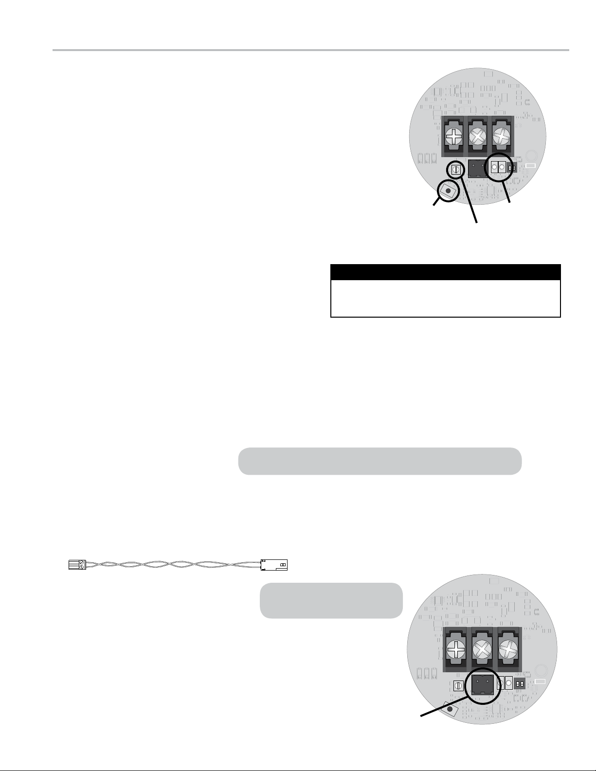
The R1 Input Signal Sensitivity Adjustment is a valuable tool that, in addition
to SP714-S2i being directly mounted to the turbine meter, allows effective
operation in noisy environments. The R1 is a potentiometer that sets the
amplitude of the input signal (from the pickup coil) that the SP714-S2i will
accept as a valid pulse.
Adjusting R1 allows the SP714-S2i to differentiate between the input signal
and any noise in the system. Turning the R1 clockwise decreases the
amplitude of the input signal required for a valid pulse, and turning the R1
counterclockwise increases the required amplitude.
The detection level of the R1 potentiometer is set at approximately 17 mV
rms at the factory. A red varnish is applied to the potentiometer screw to seal
the factory setting.
SETTINGS & DIAGNOSTICS
SW1
S1
JU4
D1 D2
GND
TB2
S2
R1
TB1
ONON
12
GND
1
R1
Input Sensitivity
Adjustment
sW2
Diagnostic Test
Oscillator
D1 & D2
Diagnostic LEDs
There are two Diagnostic Operational LEDs (D1 and D2) on the SP714-S2i PC board that indicate the current
operational status of the preamplier. The green LED (D1) indicates the power supply status. When the green LED is
on, the power supply is sufcient. When the LED is dim or ashing, the preamplier does not have sufcient power.
The red LED (D2) indicates the status of the signal traveling through the preamplier. The red LED ashes at the
same rate as the frequency as the signal passing through the SP714-S2i. If the LED is not ashing, no signal is
passing through the amplier. If the signal frequency is above 40 Hz, the light will ash very quickly and the LED will
appear to be constantly illuminated. If the input into the SP714-S2i stops on a positive portion of the signal pulse, the
LED will be illuminated constantly.
The SW2 Diagnostic Test Oscillator veries that the SP714-
S2i is operational. To activate the test, press the SW2 push
button. A 10 Hz signal will be introduced into the SP714-
S2i signal output pins (TB1). For best results, use the SW2
Diagnostic Test Oscillator without the presence of the pickup
coil signal.
If an input signal from the pickup coil is present, the 10 Hz
signal from the SW2 can disrupt the SP714-S2i output signal
and an error will be detected by the pulse acquisition device.
Do Not Use the SW2 During Operation
The D1 and D2 LEDs are inoperable in the 2-wire Standard conguration.
Polarity of the connector at the
pickup coil is not important.
Maintenance - CPU Board Replacement
The CPU board (PN 85025) is the only SP714-S2i part available for purchase. If you are replacing the 85025 CPU
board, the wiring harness, which connects the pickup coil and to the SP714-S2i CPU board, must be unplugged from
the old CPU board and plugged into the replacement board, then wired appropriately.
1. Remove the SP714-S2i housing cover.
2. Pull the CPU board from the housing, disconnect the
wires to the power supply and the pulse acquisition
device, and unplug the wiring harness.
3. Plug the wiring harness into the replacement CPU board,
wire the replacement CPU board to the power supply
and the pulse acquisition device, set the board into the
housing, and replace the housing cover. See pages 7-10 for
detailed instructions.
Wiring Harness
SW1
S1
JU4
D1 D2
GND
TB2
S2
R1
TB1
ONON
12
GND
1
Input signal
connector
11

© 2013 Liquid Controls
Pub. No. 500372
(8/2013)
105 Albrecht Drive
Lake Bluff, IL 60044-2242
1.800.458.5262 • 847.295.1050
Fax: 847.295.1057
www.lcmeter.com
TopTech SySTemS
1124 Florida Central Parkway
Longwood, FL 32750
(407) 332-1774
Nateus Business Park
Nieuwe Weg 1-Haven 1053
B-2070 Zwijndrecht (Antwerp), Belguim
+32 (0)3 250 60 60
Liquid conTroLS
105 Albrecht Drive
Lake Bluff, IL 60044
(847) 295-1050
SAmpi
Via Amerigo Vespucci 1
55011 Altopascio (Lucca), Italy
+39 0583 24751
ideX FLuid And meTering pvT. LTd.
Survey No. 256, Alindra
Savli GIDC, Manjusar
Dist. Vadodara 391 770
Gujarat, India
+91 2667 662001
Liquid conTroLS SponSLer
105 Albrecht Drive
Lake Bluff, IL 60044
(847) 295-1050
FAure hermAn
Route de Bonnetable
B.P. 20154
72406 La Ferté-Bernard Cedex, France
+33 (0)2 43 60 28 60
4702 North Sam Houston Parkway West, Suite 100
Houston, TX 77086
(713) 623-0808
corken
3805 Northwest 36th St.
Oklahoma City, OK 73112
(405) 946-5576
Table of contents
Other Sponsler Amplifier manuals


