Sporlan PSK201 User manual

PSK201
Digital Thermostats for Medium Temperature Refrigerating Units
INSTALLATION AND OPERATING INSTRUCTIONS
1 GETTING STARTED
1.1 Important
Read these instructions carefully before installing and operating
this controller and follow all addtional information for installation
and electrical connection. Keep this guide for future reference.
1.2 Installing the controller
Additional information for installation:
•59.0mm(2.322in)isthemaximumdepthwithscrewterminal
blocks
•83.0mm(3.267in)isthemaximumdepthwithextractableterminal
blocks
•thepanelthicknessmustnotbegreaterthan8.0mm(0.314in)
•workingconditions(workingtemperature,humidity,etc.)mustbe
between the limits indicated in the technical data
•donotinstallthecontrollerclosetoheatsources(heaters,hotair
ducts,etc.),devicescontaininglargemagnets,locationssubjectto
directsunlight,moisture,humidity,dust,mechanicalvibrations
or shocks
59.0 (2.322)
83.0 (3.267)
75.0 (2.952)
33.0
(1.299)
panel cut out
A
B
Size - mm (inches)
Installation - Panel mounting, with click brackets (supplied by the builder).
Dimension Minimum Typical Maximum
mm inches mm inches mm inches
A 71.0 2.79 71.0 2.79 71.8 2.82
B 29.0 1.14 29.0 1.14 29.8 1.17
Electrical Connection
PSK201
•accordingtosafetyregulations,protectionagainstaccesstoelectrical
parts must be ensured by a correct installation of the controller; the
parts that ensure this protection must be installed so that they can not
beremovedwithouttheuseofatool.
1.3 Wiring diagram
Additional information for electrical connection:
•donotuseelectricorpneumaticscrewdrivers/wrenchesonthe
terminal block connections
•ifthecontrollerhasbeenmovedfromacoldlocationtoawarmone,
condensation can occur on the inside of the unit causing unsafe or
unreliable operation; wait at least one hour before attempting to
power up and use the controller
•makesurethatthesupplyvoltageandfrequencyarecorrectforthe
power supply of the controller
•alwaysdisconnectpowerfromthecontrollerbeforeservicingit
•thiscontrollerisnotintendedtobeusedasasafetycontroldevice
•forservicingorrepair,pleasecontactyourParkerSporlanSales
Engineer.
2 USER INTERFACE
2.1 Turning on/o the controller
eunitisturnedonwhenpowerissuppliedtoit,andlikewiseturns
owhenpowerisremoved.
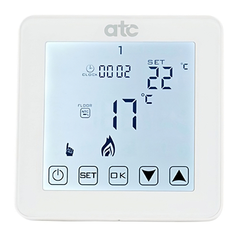
2.2 e display
When the unit is turned on during normal operation the display will
show the cabinet temperature.
2.3 Activating the defrost by hand
•makesurenoprocedureisrunning
•pressandhold for4seconds.
electric
system
1234
51
011
K1
power
supply
comp.
cabinet
max. 10 A
PSK201
September 2012 / Bulletin 100-50-6.1

Page 2 – Bulletin 100-50-6.1
3 SETTINGS
3.1 Setting the working setpoint
•makesurenoprocedureisrunning
•press : LED will ash
•press or within15seconds;alsolookatparametersr1,r2andr3
•press ordonotpressanykeyfor15seconds.
YoualsocanmodifytheworkingsetpointthroughparameterSP.
3.2 Setting conguration parameters
To gain access to the procedure:
•makesurenoprocedureisrunning
•pressandhold and for4seconds:thedisplaywillshow“PA”
•press
•press or within15secondstosetdisplayto“-19”
•press ordonotpressanykeyfor15seconds
•pressandhold and for4seconds:thedisplaywillshow“SP”.
To select a parameter:
•press or
To modify a parameter:
•press
•press or within15seconds
•press ordonotpressanykeyfor15seconds.
Toquittheprocedure:
•pressandhold and for4secondsordonotpressanykeyfor
60seconds.
Switch off/on the power supply of the controller after the
modification of the parameters.
3.3 Restoring the default value of conguration parameters
•makesurenoprocedureisrunning
•pressandhold and for4seconds:thedisplaywillshow“PA”
•press
•press or within15secondstosetthedisplayto“743”
•press ordonotpressanykeyfor15seconds
•pressandhold and for4seconds:thedisplaywillshow“dEF”
•press
•press or within15secondstosetthedisplayto“149”
•press ordonotpressanykeyfor15seconds:thedisplaywill
show “dEF”ashing4seconds,afterwhichthecontrollerwillquit
the procedure
•switcho/onpowertothecontroller.
Make sure the default value of the parameters is correct, in
particular note if the probes are PTC probes.
4 SIGNALS
4.1 Signals
LED EXPLANATION
LED compressor
iflit,thecompressorwillbeturnedon
if ashing:
•themodiedworkingsetpointwillberunning
•acompressorprotectionwillberunning(parametersC0
andC2;thecompressordelaysincetheendofthecabinet
probeerroris2minutes)
LED defrost
iflit,thedefrostwillberunning
LED alarm
iflit,analarmwillberunning
°C °CLED
iflit,temperaturemeasurementswillbeindegrees
Celsius(parameterP2)
°F °F LED
iflit,temperaturemeasurementswillbeindegrees
Fahrenheit(parameterP2)
5 INTERNAL DIAGNOSTICS
5.1 Internal diagnostics
CODE EXPLANATION
Pr1 Cabinetprobeerror
Solution:
•lookatparameterP0
•checktheintegrityoftheprobe
•checktheconnectionbetweencontrollerandprobe
•checkthecabinettemperature
Eects:
•thecompressorwillbeturnedon
Whentheconditionsthattriggeredthealarmarenolongerpresent,the
controller will return to normal operation.
6 TECHNICAL DATA
6.1 Technical data
Frontal bezel protection:IP65.
Connections (use copper conductors only): screw terminal blocks
(powersupply,inputandoutput).
Working temperature:from0to55°C(32to131°F),10to90%
relativehumidity(withoutcondensation).
Power supply:115VAC/230VAC,50/60Hz,3VA(approximate).
Insulation class:2.
Measure inputs:1(cabinetprobe)forPTC/NTCprobes.
Working range:from-50.0to150.0°C(-50to300°F)forPTCprobe,
from-40.0to105.0°C(-40to220°F)forNTCprobe.
Resolution:0.1°C/1°C/1°F.
Digital outputs:1relay:
•compressorrelay:16res.A@250VAC(change-
overcontact);5FLA,30LRA.
The maximum current allowed on the load is 10 A.

Bulletin 100-50-6.1 – Page 3
7 WORKING SETPOINTS and CONFIGURATION PARAMETERS
7.1 Working setpoints
7.2 Conguration parameters
Minimum Maximum U.M. PSK201 Working Setpoints
r1 r2 °C/°F 0.0 working setpoints
Parameters Minimum Maximum U.M. PSK201 Working Setpoints
SP r1 r2 °C/°F 0.0 working setpoints
Parameters Minimum Maximum U.M. PSK201 Temperature Inputs
CA1 -25.0 25.0 °C/°F 0.0 cabinet probe offset
P0 0 1 — 1
kind of probe
0 = PTC
1 = NTC
P1 0 1 — 1 display decimal point value during normal operation (Celsius mode only)
1 = YES
P2 0 1 — 0
unit of measure, temperature
0 = °C
1 = °F
Parameters Minimum Maximum U.M. PSK201 Setpoints
r0 0.1 15.0 °C/°F 2.0 working setpoint differential
r1 -99.0 r2 °C/°F -50.0 minimum working setpoint
r2 r1 99.0 °C/°F 50.0 maximum working setpoint
Parameters Minimum Maximum U.M. PSK201 Compressor Protections
C0 0 240 min 0 compressor delay after turning on the controller
C2 0 240 min 3 minimum time the compressor remains turned off
Parameters Minimum Maximum U.M. PSK201 Defrost
d0 0 99 h 8 defrost interval
0 = the defrost at intervals will never be activated
d3 0 99 min 30 defrost duration
0 = the defrost will never be activated
d4 0 1 — 0 defrost when you turn on the controller
1 = YES
d5 0 99 min 0 defrost delay when you turn on the controller (only if d4 = 1)
d6 0 1 — 1
temperature shown during the defrost
0 = cabinet temperature
1 = if, upon the activation of defrost, the cabinet temperature is below
“working setpoint + r0”, at most “working setpoint + r0”; if, upon the
activation of defrost, the cabinet temperature is above “working setpoint
+ r0”, at most the cabinet temperature to the defrost activation

Parker Hannin Corporation
Sporlan Division
206 Lange Drive, Washington, MO 63090 USA
phone 636 239 1111
fax 636 239 9130
www.sporlan.com
Bulletin 100-50-6.1 / 92012© 2012 Parker Hannin Corporation.
⚠WARNING – USER RESPONSIBILITY
Failure or improper selection or improper use of the products described herein or related items can cause death, personal injury and property damage.
This document and other information from Parker Hannifin Corporation, its subsidiaries and authorized distributors provide product or system options for further investigation by
users having technical expertise.
The user, through its own analysis and testing, is solely responsible for making the final selection of the system and components and assuring that all performance, endurance,
maintenance, safety and warning requirements of the application are met. The user must analyze all aspects of the application, follow applicable industry standards, and follow
the information concerning the product in the current product catalog and in any other materials provided from Parker or its subsidiaries or authorized distributors.
To the extent that Parker or its subsidiaries or authorized distributors provide component or system options based upon data or specifications provided by the user,
the user is responsible for determining that such data and specifications are suitable and sufficient for all applications and reasonably foreseeable uses of the components or
systems.
For safety information see the Safety Guide at www.parker.com/safety or call 1-800-CParker.

