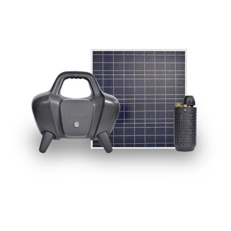
Spowdi Pro MKII User manual

Doc number: 001 Revision: PA18English language (original)
Installation manual
Solar-powered water pump
Mobile Pro MKII

2
Doc number: 001 Revision: PA18
Table of Content
1 How to read this manual ............................................................................ 4
2 Safety............................................................................................................ 5
2.1 Safety information .........................................................................................5
2.2 Markings..........................................................................................................5
3 Packaging ..................................................................................................... 5
4 System overview.......................................................................................... 6
4.1 System components........................................................................................6
4.2 Extension components...................................................................................6
4.3 Maintenance parts..........................................................................................6
4.4 PMB Overview.................................................................................................7
4.5 Pump unit Overview ......................................................................................7
5 Unpack items ............................................................................................... 7
6 How it should look after setting up ........................................................... 8
7 How to install............................................................................................... 9
7.1 Solar panel and PMB ......................................................................................9
7.2 PMB and pump unit...................................................................................... 11
7.3 Piping.............................................................................................................12
8 How to test system .................................................................................... 14
8.1 Test procedure.............................................................................................. 14
8.2 Ifwaterdoesnotow ..................................................................................15
9 How to complete installation................................................................... 16
9.1 How to extend tubes..................................................................................... 16
10 Final check ................................................................................................ 17

3
Doc number: 001 Revision: PA18
11 Product features........................................................................................ 18
12 Technicalspecications(Freeow)........................................................ 19
13 Storage........................................................................................................ 19
14 Transport ................................................................................................... 19

4
Doc number: 001 Revision: PA18
1 How to read this manual
The manual describes a general installation. For the system to work properly it needs
Move according to arrow.
Points out area of interest.

5
Doc number: 001 Revision: PA18
2 Safety
2.1 Safety information
Weight
MOBILE PRO MK II SOLAR PANEL DRIP KIT
7.0 kg 12.2 kg 45.0 kg
Electrical hazard
Do not short circuit solar panel contacts.
Do not open any components.
If any part is malfunctioning contact your local service center.
2.2 Markings
3 Packaging
Discard all packing material according to local law and regulations.

6
Doc number: 001 Revision: PA18
4 System overview
4.1 System components
4.2 Extension components
4.3 Maintenance parts
A - Power
Management Box
(PMB)
B - Pump Unit
with Ø8mm, 5m
air hose
C - Pressure Vessel with
Ø25mm T-connector
D - 150W Solar
panel
E - Water tube
Ø25mm, 1 meter
H - Straight connector
Ø25mm
Membrane Spowdi tool
I - Quick connector
Ø16mm
J - Quick connector
Ø8mm
F - Water extraction tube
Ø25mm, 30cm
G - Air tube
Ø16mm, 0.8 meter

7
Doc number: 001 Revision: PA18
4.4 PMB overview
4.5 Pump unit overview
5 Unpack items
1
2 Check that all items are included and if there are any damaged parts.
Contact your local service centre.
Front side
Top view
K - Power button
P - Quick connector
Ø16mm
O - Straight connector
Ø25mm
Q - Ø8mm Air hose hole
L - Air out
M - 12V Solar cable input
N - Main switch
Back side

8
Doc number: 001 Revision: PA18
6 How it should look after setting up
Max 5 m
30cm
Solar panel facing sun
Solar panel must
not be shadowed PMB behind Solar panel
Pressure vessel max 5m
16mm air hose above
water surface
Pump unit 30cm below
water surface
Straight and tied up at
three points

9
Doc number: 001 Revision: PA18
7 How to install
7.1 Solar panel and PMB
1 Connect positive and negative wires of
solar panel to back of PMB (M).
2
PMB.
M
N
OFF
ON
Connection of solar panel and PMB

10
Doc number: 001 Revision: PA18
3 If connection is right and there is power
from solar panel or battery inside PMB,
power button (K) will light up blue.
If power button does not light up, see
Troubleshooting, chapter 3.1 in the
service manual.
4 Test PMB boot up by pressing down
power button and feel air pressure at air
outlet (L) on back of PMB.
5
test is completed.
Note!
1. In order for system to run smoothly, sun radiation has to be more than 750W/
mand the battery must not be empty. If boot up does not happen, try to let solar
up system again by pressing down power button. Charging will happen if the main
switch is turn on while connected to solar panel.
K
Service Manual
L

11
Doc number: 001 Revision: PA18
7.2 PMB and pump unit
1 ge colour)
from pump unit to air outlet (L) at back
of the PMB.
2 Cut a 15cm section of Ø8mm air hose
from air outlet connection point at back
of PMB. This section of 15cm (Ø8mm air
hose) is a permanent installation to the
PMB.
3 Connect the two ends of the Ø8mm air
4 Air hose connection is completed.
Connection of Ø8mm air hose from pump unit to PMB
L
15 cm
J

12
Doc number: 001 Revision: PA18
Note!
1. When you want to disconnect
PMB from Pump unit, disconnect
Ø8mm air hose that belongs to
attached.
connector press down ring on the
release tube as there will be some
pressure holding the tube. Push
and pull tube on pump unit (B).
7.3 Piping
1 Attach Ø16mm air tube (G) into Ø16mm
connector (P) on pump unit (B).
J
B
B
G
P
Connection of Ø16mm air hose, Ø25mm water outlet pipe to pump unit and pressure vessel

13
Doc number: 001 Revision: PA18
2 Install Ø25mm water tube (E) into
Ø25
unit according to picture below.
Note!
Take note of the arrangements of the four parts.
3 Follow the above procedure to install
pressure vessel (C), with Ø25mm
point of Ø25mm water tube.
4
(including in the packaging) to
same way.
5 Piping installation is completed.
E
O
Remove top cap Make sure there are four
parts in the top cap
Put all four parts
onto water tube
Push down and tighten
top cap with pump unit
C
F

14
Doc number: 001 Revision: PA18
8 How to test system
8.1 Test procedure
1 Put pump unit into the water.
Pump unit must be completely
submerged in water and 30cm below
water surface.
2 Make sure Ø16mm air tube is above the
water surface.
3 Turn on the main switch then press
power button (K) on the front of the
4
and then the main switch.
Note!
The factory setting is set for 5 meter head use, if you have more than 5 meter, you
might need to adjust air regulator setting for the pump unit to work. Please refer
K
F
K

15
Doc number: 001 Revision: PA18
8.2 Ifwaterdoesnotow
1 Grip Ø25mm water tube and shake
pump unit up and down a few times.
2 Block Ø16mm air tube outlet with your
thumb for 2 seconds and repeat a few
time until you see it pumping.
3 If still no water. Check if there are any
leakage at all the connection points.
Note!
When system is operating, always check if there are any air/water leakage at ALL
connecting points in order for best performance and life of system. You can use
your hand to feel if there are any air leakage from the connecting points. For water
leakage, you can see water leaking via naked eye.

16
Doc number: 001 Revision: PA18
9 How to complete installation
1
tube by attaching a cable ties or tape.
Attach it 30cm above top of pump unit.
2
cable tie/tape is at water level surface.
3
as straight as possible.
Make sure pressure vessel is straight
and is not dangling down.
Tie at lease 3 section to the pole to
ensure good secure of all the tubing and
hose. It is also recommended to tie top
part of pressure vessel to pole.
9.1 How to extend tubes
Depending on the type of installation, you may need optional tubes and connectors.
dealer.
‘Piping’ (Pg.no 12, in this manual).
30 cm

17
Doc number: 001 Revision: PA18
10 Final check
Max 5 m
30cm
Solar panel facing sun
Solar panel must
not be shadowed PMB behind Solar panel
16mm air hose above
water surface
Pump unit 30cm below
water surface
Straight and tied up at
three points
Pressure vessel max 5m

18
Doc number: 001 Revision: PA18
11 Product features
CHARACTERISTICS COMMENTS
Yes, when it is connected to the solar panel.
Yes, without any negative impact on the system.
Yes, dirty water, i.e. with gravel and mud, will not
be a problem.
Yes, it can be maintained easily if scheduled main-
tenance is followed
Yes, it can be easily carried by one person (total
Yes, a backup battery for 20 min operation is in-
built.
Yes, drip irrigation is recommended.
Yes, it is compatible with most types of micro
sprinklers.

19
Doc number: 001 Revision: PA18
12 Technicalspecications(Freeow)
PV ARRAY MOTOR
CAPACITY
HEAD WATER OUTPUT
(L/MIN)
WATER OUTPUT
(L/DAY)
150 Wp 0,1 hp 10 meters (1) 10 (2) 6 300 (3)
150 Wp 0,1 hp 5 meters 25 (2) 15 900 (3)
150 Wp 0,1 hp 1 meter 35 (2) 21 000 (3)
(1) Head more then 5m not recommended when used for drip irrigation.
13 Storage
• Do not store more than one month without charged battery.
• Do not store at temperature higher than 45 degress celsius.
•
14 Transport
• Disconnect all the cables from solar panel and PMB.
• Unplug the pipe connections.
•
• Handle with care.

Spowdi AB
www.spowdi.com | info@spowdi.com
Other manuals for Pro MKII
2
Table of contents
Other Spowdi Water Pump manuals
Popular Water Pump manuals by other brands

Kawamoto Pump
Kawamoto Pump RCJ Series instruction manual

Trotec
Trotec TGP 1000 E Original instructions

Champion Pump
Champion Pump CPSTEP5 Series installation manual

Goulds
Goulds e-SV instruction manual

Wilo
Wilo Yonos PICO 15/1-6 Installation and operating instructions

Abbott
Abbott PLUM A + System Operating Manual

Goulds Pumps
Goulds Pumps ICS Installation, operation and maintenance instructions

Pentair Pool Products
Pentair Pool Products Swimmey Use and maintenance manual

Ulvac
Ulvac PVD-180 instruction manual

Brave
Brave BRP500TP2 owner's manual

Ranqer
Ranqer 29028 instruction manual

PondMAX
PondMAX Evo II series instruction manual