Sprague SM-3 User manual

Operation and
Maintenance Man u al
MODEL SM-3
AIR-OPERATED LIQUID MINIPUMP
10195 Brecksville Road
Brecksville, OH 44141 USA
Telephone: 440-838-7690 • Fax: 440-838-7513
www.cwfc.com
ISSUED MARCH 2004
Sprague Products
Division of Cur
tiss-
Wr
ight Flow Control Corporation
Sprague Products
®
Sprague Products
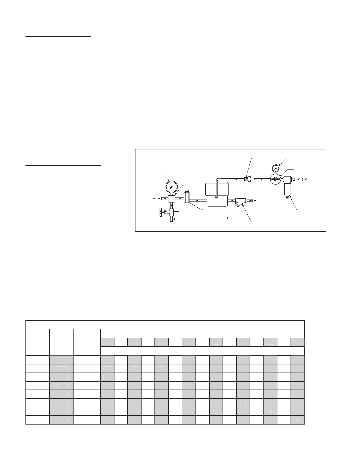
TABLE OF CONTENTS
Page
Method of Operation
...............................................................
...............................................................
..............................
2
Safety
...............................................................
...............................................................
.......................................................
3
Installation
...............................................................
...............................................................
...............................................
3
Operation
...............................................................
...............................................................
.................................................
4
Maintenance
...............................................................
...............................................................
.............................................
4
Dimensional Data
...............................................................
...............................................................
.....................................
5
Troubleshooting
...............................................................
...............................................................
.......................................
6
User Con gured Operation Modes
...............................................................
...............................................................
...........
7
Disassembly Procedure
...............................................................
...............................................................
.....................
8-11
Reassembly Procedure
...............................................................
...............................................................
....................
12-14
Assembly Drawings, Parts Lists Including Service Kits
...............................................................
..................................
15-18
METHOD OF OPERATION
2
Pump Ratio Selections Chart
For the following pump models: SM-3A, SM-3S
100 psi Driving Air Supply
Nominal
Ratio
Max.
Output
Pressure
Disp. Per
Stroke
Cu. In.
LIQUID DISCHARGE PRESSURE – PSI
0
100
200
350
500
1000
1500
2M
4M
6M
8M
10M
12M
15M
20M
CAPACITIES – CUBIC INCHES PER MINUTE APPROXIMATE
5:1
575
1.050
550
330
275
180
10:1
1150
0.527
476
350
200
180
150
10
20:1
2300
0.263
305
280
210
160
110
75
60
15
35:1
4030
0.150
158
140
120
100
90
60
50
40
60:1
6900
0.085
98
90
80
70
60
31
25
22
17
100:1
11500
0.053
58
55
53
50
48
40
30
21
16
14
10
150:1
17300
0.035
39
38
37
36
35
28
25
20
12
11
9
7
6
225:1
25900
0.023
24
23
22
21
20
18
17
16
9
8
7
6
5
4
3
Nominal Performance (Based on Operating Air Supply of max 15 scfm @ 100 PSI)
Example:
SM-3A-010 pump has an nominal ratio of 10 to
1 or 10 psi liquid pressure for each 1 psi of operating air
pressure.
In operation a SM-3A-010 pump using 100 psi of input air
will actually produce a maximum liquid output pressure of
1150 psi; 80 psi air will produce an output pressure of 920
psi air; 60 psi air will produce an output pressure of 690 psi
output; and 40 psi air will produce an output pressure of
460 psi output.
The Sprague pump develops high output
pressure by applying the principle of dif-
ferential areas.
The pump has a large area air piston,
air-driven at low pressures. This air piston
drives a small area liquid piston that in turn
pumps liquids at high pressures.
The liquid output pressure is determined
by the ratio between the area of the air
driven piston, the area of the liquid driven
piston, and the applied operating air pressure.
The area relationship of the air piston to the liquid piston is
referred to as the pump ratio. A nominal ratio is indicated
in the dash number, which follows the pump model basic
number.
Liquid
Pressure
Line to
Hydraulic
Cir
cuit
Bleed Line
to Reser
voi
r
Bleed V
alve
Restrictor
V
alve – Required for
Burst T
esting
Burst TestingBurst T
Filter – 10 Micron
Liquid Supply
Line from
Reser
voir
Air Filter
10 Micron
Compressed Air
Line Thru
Reducer into
Air Filter
(1/4
″
NPT Port)
″ NPT Port)″
Air Pressure
Regulator
Air
Pressure
Gauge
Air
Shut-Off
V
alve
SM-3 Pump
Manifold
Liquid
Pressure
Gauge
PUMP AND ACCESSORIES - TYPICAL ARRANGEMENT
FIGURE 1 Pump installed in a typical circuit with recommended accessories which are available
from Sprague Products

3
SAFETY
SM-3 minipumps are designed to provide high levels of safety, provided basic safety guidelines are followed.
AIR MODULE
Make sure that all air connections are made up properly.
If NPT connections have been speci ed, the NPT t-
ting should be wrapped with two turns of PFTE tape and
screwed into the plastic plate nger tight. Tape within one
or two threads of the end.
DO NOT OVERTIGHTEN THESE FITTINGS.
MAXIMUM TORQUE 25 IN-LBS.
Inspect ttings regularly to make sure they have not loos-
ened in service.
All air side components must be correctly tted when ser-
vicing the pump – please refer to the maintenance section
for guidance.
There are no external moving parts. However, make sure
that air is disconnected when working on pumps to avoid
injury. Maximum Drive Air Pressure 125 PSI
INSTALLATION
LOCATION
Minipumps should be mounted on a at surface which
maybe at any angle.
Location is preferably clean and dry and free from solvents
or aggressive chemicals coming into contact with the
minipump.
MOUNTING
4 slots are provided in the minipump main body for mount-
ing. Details of bolt hole positions are shown in Figure 2
SM-3 Dimensional Data section page 5. Minipumps should
be securely mounted to a rm surface to avoid damage to
connections when the pump is operating.
DO NOT OVER-TORQUE MOUNTING BOLTS.
MAXIMUM TORQUE IS 40 IN-LBS.
Pipework should not be used to support the minipump,
plumbing should be arranged that easy removal of the mi-
nipump from the location is possible. Avoid over tight pipe
runs to minipump that require pipes to be bent to disen-
gage uid and air connections.
AIR SUPPLY
Air should be clean and dry. SM-3 pumps will be suscep-
tible to freezing due to the water vapor condensing as the
air exhausts. Filter air to 10 micron.
“AIR MUST BE DRY OR ICING WILL OCCUR.”
No air lubrication is required and is to be avoided.
EXHAUST & SEPARATION PORT
Do not block or restrict the exhaust or separation port.
Pump performance can be reduced or pump may cease to
operate.
LIQUID SUPPLY
A clean liquid supply is essential. Inlet liquid should be l-
tered to 25 micron absolute prior to entering the minipump
high-pressure body. Should dirty liquid be used, the high
pressure seals and both check valves will wear excessively,
leading to shortened operation between maintenance.
LIQUID MODULE
SM-3 minipumps can generate very high liquid pressures
and great care should be taken in use and maintenance.
Make sure that the system pressure and any pressure
potentially trapped in the pump has been released prior to
disassembly.
Connections are either NPT, or for ratios of 100 and higher,
coned and threaded H.P. tube tting on the outlets.
NPT liquid connections should be wrapped with two turns
of PTFE tape and screwed nger tight into the connection,
then turned with a wrench a further 1 to 2 full turns.
Note:
If the tting is found not to be pressure tight, make
Note: If the tting is found not to be pressure tight, make Note:
sure that pressure is bled to zero prior to further tightening.
Coned and threaded ttings should be made up in accor-
dance with the supplier's recommendations – see Nova
Swiss cataloge, available from Sprague.
DO NOT RUN ALUMINUM BODY PUMPS ON WATER OR
WATER WITH ADDITIVES.

OPERATION
STARTING
SM-3 minipumps are supplied in standard operating mode,
which means they are ready to run with a single air connec-
tion and the liquid inlet and outlet connected.
In this mode all that is required is a clean air supply con-
nected to the main air inlet. See assembly drawings for port
clari cation.
An Air Filter / Regulator is required for standard opera-
tion. The air supply should be regulated to a maximum of
125psi. An air shut off valve should also be installed.
TO START MINIPUMP, OPEN AIR SUPPLY LINE SLOWLY.
Should minipump not operate, see trouble shooting section.
NOTE
: Pump Ratios 60: 1 and above may
require positive pressure at liquid inlet to prime, or to be
lled manually as follows:
depress inlet check valve poppet and pour clean liquid to ll
pumping chamber. Reconnect plumbing and start pump.
STOPPING
Minipump may stall with air supply still connected.
MINIPUMP CAN BE STOPPED AT ANY TIME WHEN RUN-
NING, BY SIMPLY SHUTTING OFF THE AIR SUPPLY.
Note: If other operating modes have been selected, the
minipump stop-start characteristics are different – see user
con gured operating mode section.
4
MAINTENANCE
TOOLS
The following is a list of essential and useful tools required
to maintain the SM-3 minipumps:
Long nosed pliers
Medium at blade screwdriver
Soft Nylon Hammer
Selection of wrenches
Bench mounted vice
Torque wrench with open-ended adapters
Water soluble cleaning uid and small brush
Accrolube Te on
®
grease or equivalent o-ring lubricant
Anti-seize lubricant
DISASSEMBLY
Minipump disassembly is in two parts – air module then
liquid module.
See disassembly sequence on following pages.
CLEANING AND INSPECTION
Once all the components have been carefully laid out, they
should be washed in an aqueous oil degreaser. Parts should
be rinsed in clean tap water and dried, laid out for inspection.
All parts should be inspected for signs of wear.
Things to look for:
Score marks on piston shafts, bodies, and back-up rings.
Seal damage.
Excessive wear on check valve seat surfaces.
Make sure all worn parts are replaced. Service kits, as
shown at the end of this manual, contain wear replacement
parts recommended by Sprague. Kits contain sealing and
small components only, individual machined components
can be ordered separately using part numbers shown on
parts lists.
REASSEMBLY
Make sure all parts are clean and that all seals are lubricated
at assembly. Minipump reassembly is the reverse to dis-
assembly, taking note of torques as shown on following
pages.
Te on is a registered trademark of the DuPont Company
5
Model
Fluid Inlet Port
Fluid Outlet Port B
Air Inlet Remote and Single Port
SM-3X-005
3/8
″
NPT
″ NPT″
3/8
″
NPT
″ NPT″
1/4
″
NPT
″ NPT″
SM-3X-010
3/8
″
NPT
″ NPT″
3/8
″
NPT
″ NPT″
1/4
″
NPT
″ NPT″
SM-3X-020
3/8
″
NPT
″ NPT″
3/8
″
NPT
″ NPT″
1/4
″
NPT
″ NPT″
SM-3X-035
3/8
″
NPT
″ NPT″
3/8
″
NPT
″ NPT″
1/4
″
NPT
″ NPT″
SM-3X-060
3/8
″
NPT
″ NPT″
3/8
″
NPT
″ NPT″
1/4
″
NPT
″ NPT″
SM-3X-100
1/4
″
NPT
″ NPT″
9/16
″
-18 NBS (1/4
″
HP)
″ HP)″
1/4
″
NPT
″ NPT″
SM-3X-150
1/4
″
NPT
″ NPT″
9/16
″
-18 NBS (1/4
″
HP)
″ HP)″
1/4
″
NPT
″ NPT″
SM-3X-225
1/4
″
NPT
″ NPT″
9/16
″
-18 NBS (1/4
″
HP)
″ HP)″
1/4
″
NPT
″ NPT″
Porting
– Standard Pumps
Mounting bolts
– 1/4
″
or M6
″ or M6″
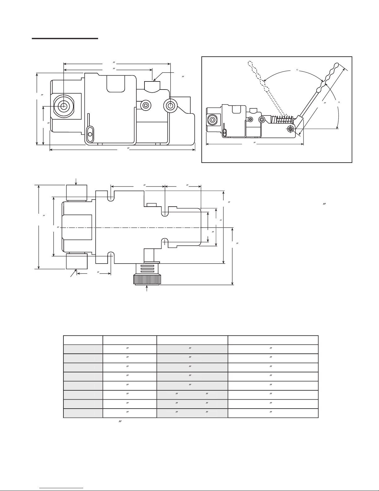
DIMENSIONAL DATA
5.62
″
4.75
″
3.93
″
2.06
″
″
7.80
″
″
Air Inlet
1/4
″
NPT
″ NPT″
60
°
60
°
12.0
″
11.25
″
2.93
″
2.12
″
3.95
″
1.92
″
1.65
″
3.25
″
1.90
″
3.20
″
5.00
″
max
Fluid
Outlet
Fluid
Inlet
Air Exhaust
Bolt Mounting Slots use1/4
″
(6mm) Fasteners
Weight:
STD. ALUM. BODY
4.5 LBS
STD. ST. STL. BODY
6.75 LBS.
HAND ALUM. BODY
5.75 LBS.
HAND ST. STL. BODY
8.00 LBS.
Hand Pump Option
Figure 2

6
TROUBLESHOOTING
TROUBLE
CORRECTION
Pump does not operate
Make sure clean air supply has correct ow and pressure. (Min. 20 PSI & 3 SCFM)
Check if pump has not stalled due to hydraulic pressure at outlet of
check valve.
Check that pilot air, if remote pilot mode selected, is at correct pressure and available
to pump.
Check that air exhaust is not blocked with ice or dirt.
Check that separation vent port is not blocked.
Leakage past air valve o-ring.
Leakage past air piston seal.
Pump operates intermittently
Check that the correct air pressure and ow is available.
against low output pressure
Pump may be icing.
Minipump appears to “cough”.
Leakage in air valve.
If checked and found OK, it is likely that a fault is inside the air control valve. Remove air control valve from minipump
and service.
Minipump does not generate
Outlet check valve: - run the pump and close the valve on the high pressure outlet.
required pressure
Shut off the drive air and if the outlet pressure drops, the outlet check valve is
contaminated or worn.
Inlet check valve: - run the pump and close the valve on the high pressure
outlet. If the pump continues to cycle, the problem is the inlet check valve.
High pressure seal: Replace the high pressure seal if liquid mists out of the
drain port
If everything checks out it is likely that the high-pressure seals have worn and require replacement. Dissassemble the uid
section of minipump and replace seals. Inspect the check valves for wear.
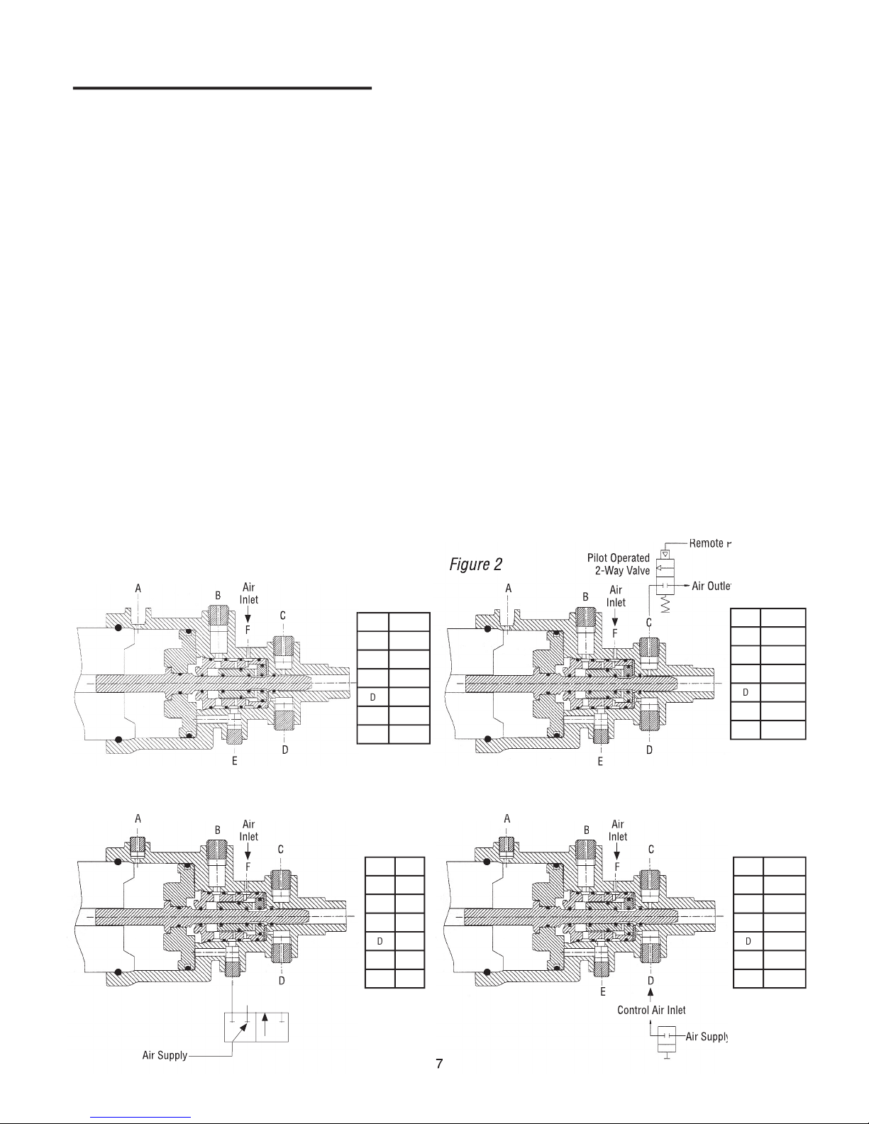
USER CONFIGURED OPERATING MODES
SM-3 minipumps have the capacity to allow the user to simply and quickly alter the way the pump operates. Minipumps
are delivered in the standard operating mode condition. For all operating modes the pilot exhaust port is tted with a vent
plug.
STANDARD OPERATING MODE
This mode of operation is shown in Figure 1. In this mode,
a single air supply is used as motive power for the air drive.
Within the air valve, a small quantity of air is bled off to act
as pilot air for the spool valve. This air is exhausted after
use through the pilot exhaust port. When air is supplied
to the minipump, the minipump operates until the balance
pressure is reached or until the air supply is switched off. In
this mode, the single stroke port is plugged off.
REMOTE OPERATION MODE
This mode of operation is shown in Figure 2. In this mode
a pilot operated 2-way valve is tted between the air supply
and the air inlet port. Pilot air is then connected to the sens-
ing port of the 2-way valve. This mode allows the pump
to be started and stopped remotely by applying air to the
2-way sensing port. In this mode, the single stroke port is
blanked off.
SINGLE CYCLE OPERATION MODE
There are two different single cycle operating con gurations shown in Figures 3A and 3B.
Figure 3A shows the schematic for direct acting single stroke control that can be eld con gured. Plug all ports
except E, which is connected to a Nornally Closed three way valve.
In order to single cycle the pump using an external generated air pulse, (each pulse powering one complete
Mini-Pump cycle) this con guration can only be Factory supplied as a SM-3X-XXX-XX-S, and should be
plumbed as shown in Figure 3B. (To run this con guration continuously provide a constant air supply at D)
A
B
F
C
E
D
Air
Air
Inlet
A
A
B
F
C
D
Air
Air
Inlet
A
B
F
C
E
D
Air
Inlet
Air Outlet
Air Outlet
Remote Pilot
Remote Pilot
Pilot Operated
2-Way Valve
Port
Plug
A
Vent
B
Muf er
C
Pilot
D
Plug
E
Plug
F
Inlet
Port
Plug
A
Vent
B
Plug
C
Vent
D
Plug
E
Plug
F
Plug
Port
Plug
A
Vent
B
Muf er
C
Vent
D
Plug
E
Plug
F
Inlet
Figure 1
Figure 2
Figure 3A
Air Supply
A
A
B
F
C
E
D
Air
Air
Inlet
Control Air Inlet
Port
Plug
A
Vent
B
Muf er
C
Vent
D
Inlet
E
Plug
F
Inlet
Figure 3B
Air Supply
Air Supply
7
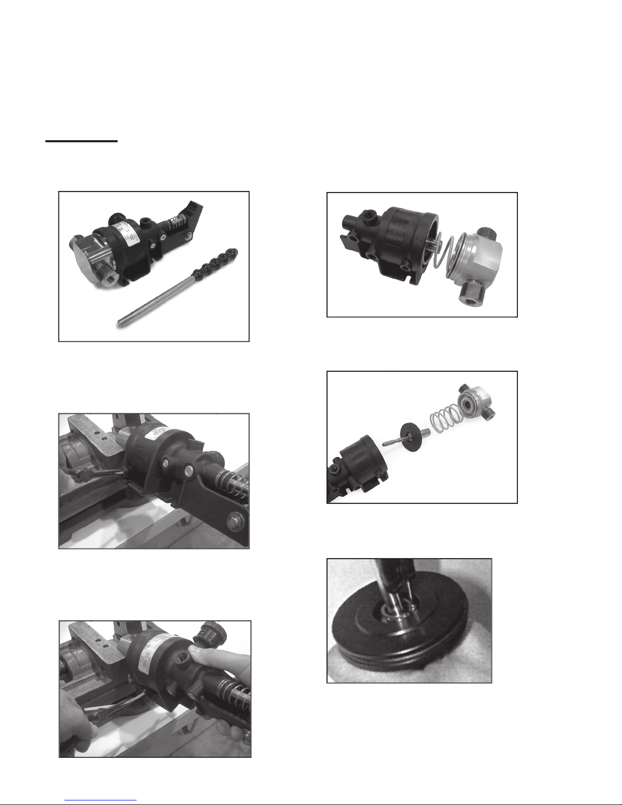
8
DISASSEMBLY
1.
SM-03 minipump as delivered. (Hand pump option
shown) Handle rod is simply inserted as shown on
page 18.
2.
Remove Spirol Pin with a 3/32 pin punch. Locate
retainer rod in slot at top of low pressure body, lever-
ing out with small screwdriver and gripping with pliers.
Remove retainer as shown.
3.
Secure H.P. Body in vice as shown. Secure end of re-
tainer rod with needle nose pliers and pull. Rotate lower
pressure housing counterclockwise to facilitate extrac-
tion of retainer.
Remove high pressure end and piston assembly from
low pressure body. Piston spring is compressed.
Be careful during disassembly.
4.
5.
Remove piston assembly from air body and spring from
high pressure end.
6.
Remove external retaining ring from piston. Be care-
ful, do not over expand retaining ring.
MANUAL OPERATION
On request, manual operation minipumps can be supplied. As with standard minipumps, they are supplied in the standard
operating mode. These minipumps can also be recon gured to remote operating or single stroke modes. The hand opera-
tion uses a hand lever, where one complete movement of the lever equates to one cycle of the minipump. The hand lever is
easily removed for convenience.

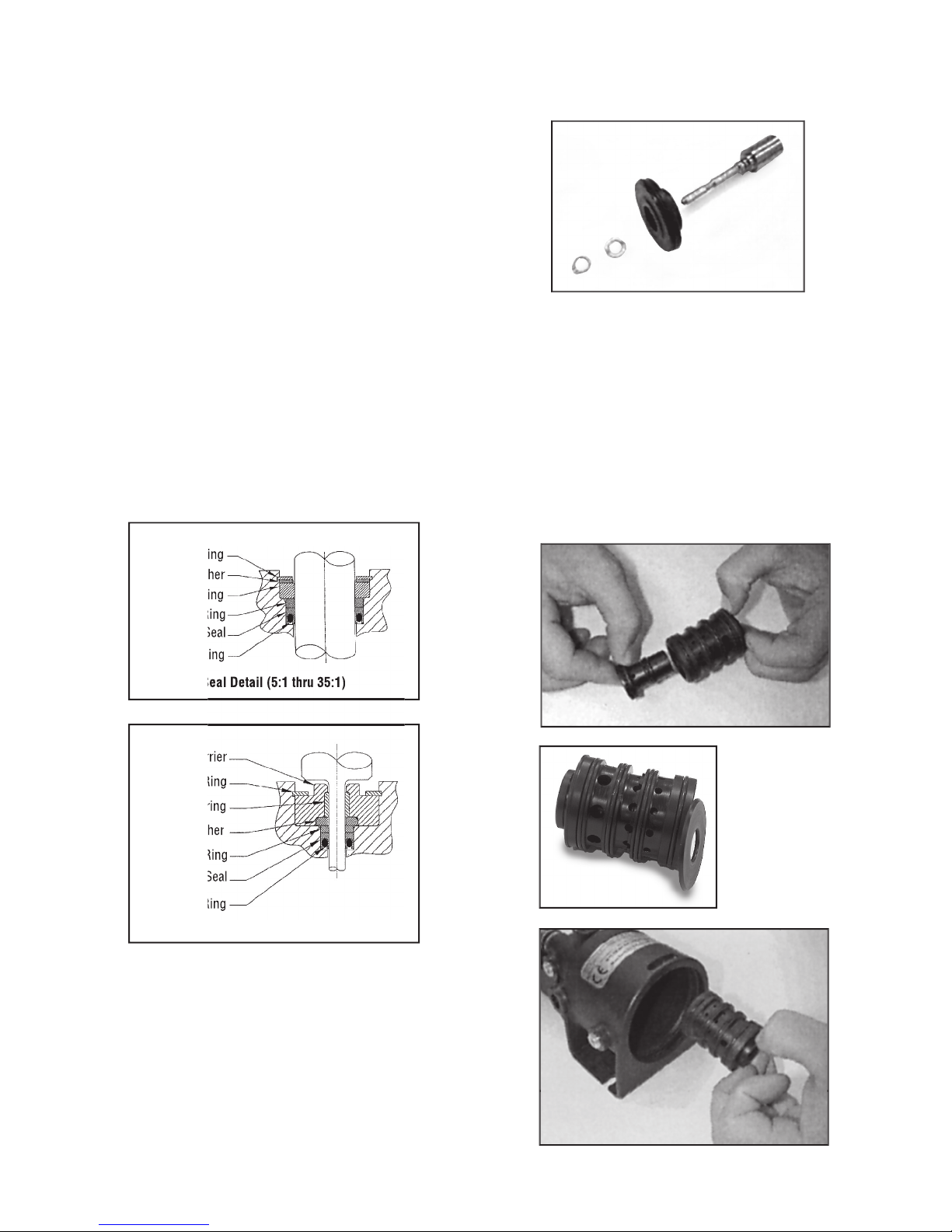
7.
Slide washer and piston off piston shaft.
8.
Remove retaining ring from high pressure body.
(Use eye protection safety glasses.)
9
9.
Remove back-up ring from high pressure body.
10.
Remove high pressure seal assembly from recess
within high-pressure body. Seal orientation under
back-up ring is as shown. See Figure 10a & 10b.
11.
Holding high pressure body in vise, remove inlet check
valve body as shown. Watch for inlet check valve parts
inside and o-ring on body.
Retaining Ring
Retaining Ring
Bearing Washer
Bearing Washer
Bearing
Bearing
Back-Up Ring
Back-Up Ring
Lip Seal
Lip Seal
O-Ring
O-Ring
Retaining Ring
Retaining Ring
Bearing Washer
Bearing Washer
Bearing
Bearing
Back-Up Ring
Back-Up Ring
Lip Seal
Lip Seal
O-Ring
O-Ring
Bearing Carrier
Bearing Carrier
Seal Detail (5:1 thru 35:1)
Seal Detail (5:1 thru 35:1)
Seal Detail (60:1 thru 225:1)
Fig. 10a
Fig. 10b

10
12.
Holding high pressure body in vice, remove intlet
check valve as shown. Watch for inlet check valve
parts inside and o-ring on gland.
12 a) =
5, 10, 20, 35 & 60:10 Ratios
12 b) =
100, 150 & 225 Ratios
13.
Holding high pressure body in vise, remove outlet
check valve body as shown. Watch for outlet check
valve parts inside and o-ring in body.
14.
Fig. a
Fig. b
Fig. c
Fig. d
Remove outlet check valve assembly from outlet check
valve body.
14 a) = 5,10, 20, 35 & 60 ratios
14 b) = 100, 150,& 225 ratios
15.
Remove retaining ring from low pressure body.

11
16.
Remove spool and sleeve by gradually applying air
pressure to main air inlet port shown while holding
piston shaft fully into sleeve (block off single cycle
port and remove protector from main exhaust port as
shown.) Do not use pliers to extract sleeve, as this will
damage sealing surfaces.
17.
Remove spool from air body.
18.
Remove spool from sleeve.
19.
Remove retaining clip and plain washer to hinge
pin.
20.
Push out hinge pin. Care to be taken as compres-
sion spring will forcibly eject handle and handle
return Spigot from low pressure body.
The following instructions, 19 to 21, apply only to
the manual operation option, (H).
21.
Handle components laid out.
12
REASSEMBLY
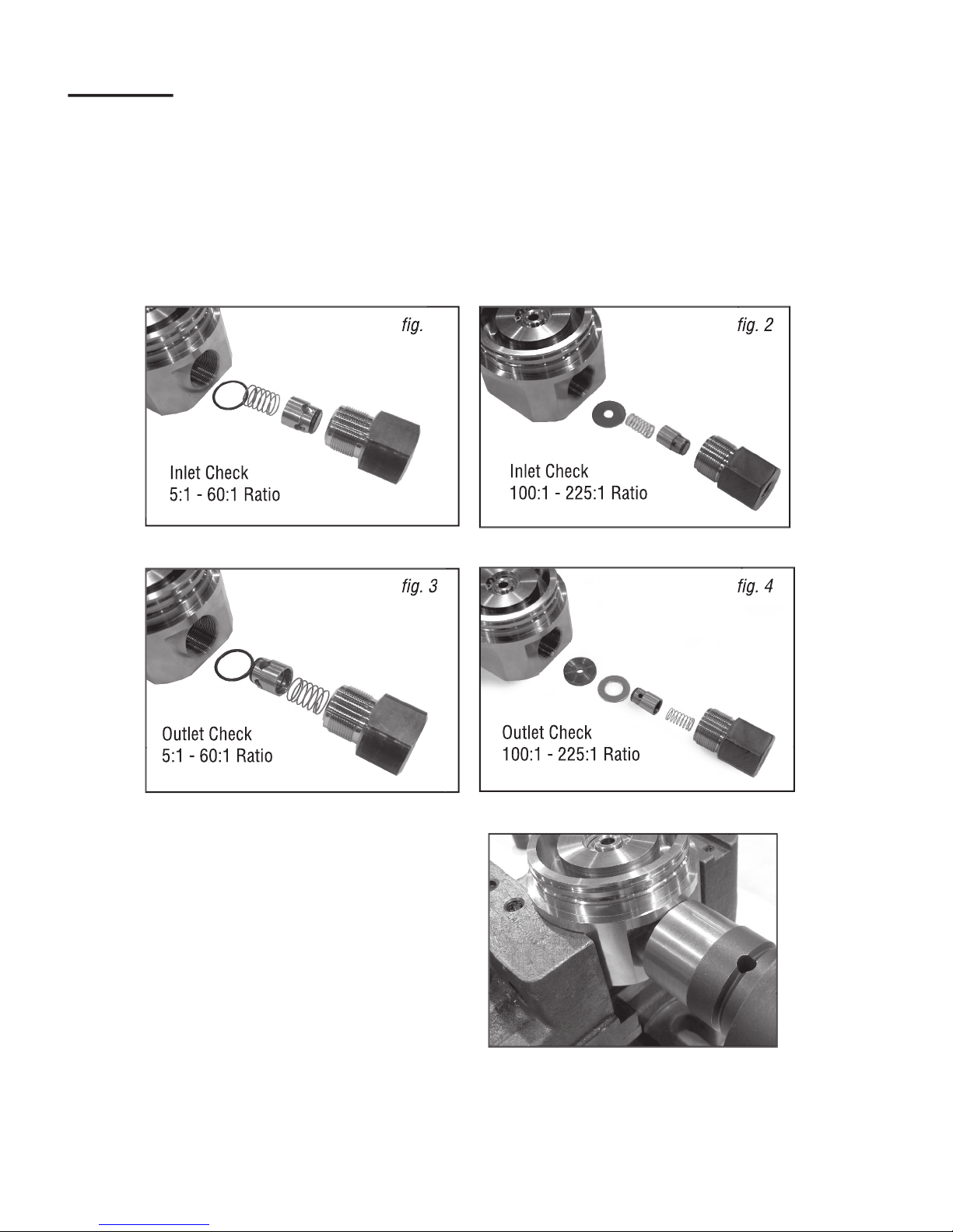
INLET & OUTLET CHECK VALVES
Before reassembling pump, wash metalic parts thoroughly
in water solution (“Simple Green”), rinse and dry. Lubri-
cate o-rings with “Accrolube” te on grease or equivalent.
Use lubricants compatible with seal compounds. Lubricate
external threads with loctite nickel anti-seize or equivalent.
Reassemble in the reverse order to disassembly, noting the
following points.
Refer to assembly drawings for part numbers and con gu-
ration.
Reassemble and install inlet and outlet check valves into
uid body. See Figure 1 - 4. NOTE: order of assembly and
position of poppets. NOTE: torque instructions. DO NOT
over-torque valve bodies and be careful to avoid crossing
threads when installing check valve bodies.
Tighten the inlet and outlet check valve bodies to the follow-
ing torques:
ALUMINUM BODY
(5-100:1 RATIO)
115-125 FT. LBS.
STAINLESS STEEL BODY
(5-60:1 RATIO)
115-125 FT. LBS.
(100-225:1 RATIO)
230-240 FT. LBS.
Inlet Check
5:1 - 60:1 Ratio
Inlet Check
100:1 - 225:1 Ratio
Outlet Check
5:1 - 60:1 Ratio
Outlet Check
100:1 - 225:1 Ratio
g. 1
g. 1
g. 2
g. 3
g. 4
Lubricate the 91417-231-29 o-ring and assemble on the air
piston. See gure below.
SPOOL/SLEEVE ASSEMBLY – Lubricate the o-rings with
“Accrolube” Te on grease or equivalent. Use lubricants
compatible with seal compounds. Assemble the external
o-rings on the sleeve, 91417-025. Assemble the external
o-rings on the spool, 91417-020 and 91417-017-29 in ap-
propriate grooves. Assemble internal o-rings in the spool
and sleeve, p/n 91417-012-41. The use of a soft o-ring pick
or plastic probe will aid in this assembly. Use care – DO
NOT scratch the o-ring or spool/sleeve. Assemble the spool
into the sleeve per assembly drawing.
13
HIGH PRESSURE SEAL
See assembly drawings for part numbers and con gura-
tion. Lubricate o-ring and assemble into the lip seal. Use
care, do not scratch or mark the o-ring or lip seal. As-
semble lip seal into high pressure body. Orientation of the
seal is CRITICAL. The open end of the lip seal is facing
the bottom. See seal detail below. Push the lip seal to the
closed end of the counterbore with an appropriately sized
plug. Next, assemble the back-up ring, these parts should
be seated at the bottom of the counterbore. Depending on
the ratio, the construction varies.
For the 5:1 thru 35:1 ratio’s, assemble the bearing, washer
and retaining ring. For the remaining ratio’s, 60:1 thru
225:1, assemble the bearing into the bearing carrier.
Assemble the bearing washer into the bearing carrier.
The chamfer on one side of the bearing washer faces the
bearing carrier. Assemble these components into the high
pressure body and install the retaining ring with the sharp
edge facing out.
The retaining ring must be completely seated into the
groove. Safety note: USE EYE PROTECTION.
LOW PRESSURE BODY – [AIR MOTOR]
AIR PISTON ASSEMBLY – Replace the 91417-013 o-ring
on the piston shaft. Lubricate the o-ring with “Accrolube”
Te on grease or equivalent. Use lubricants compatible with
seal compounds. Assemble air piston onto the piston shaft,
see orientation on assembly drawing. Assemble washer and
retaining ring sharp edge out (away from the seal). Make
sure the retaining ring is properly seated in the groove.
Retaining Ring
Retaining Ring
Bearing Washer
Bearing Washer
Bearing
Bearing
Back-Up Ring
Back-Up Ring
Lip Seal
Lip Seal
O-Ring
O-Ring
Retaining Ring
Retaining Ring
Bearing Washer
Bearing Washer
Bearing
Bearing
Back-Up Ring
Back-Up Ring
Lip Seal
Lip Seal
O-Ring
O-Ring
Bearing Carrier
Bearing Carrier
Seal Detail (5:1 thru 35:1)
Seal Detail (5:1 thru 35:1)
Seal Detail (60:1 thru 225:1)
NOTE: Orientation
of spool washer.
14
LOW PRESSURE AIR BODY – Lubricate the o-ring with
“Accrolube” Te on grease or equivalent. Use lubricants
compatible with seal compounds. Install the 91417-012-1
o-ring in the low pressure body internal o-ring groove. Use
a soft o-ring pick or plastic probe to aid in this assembly.
See assembly drawing for detail SM3-LP. Lubricate the
middle bore of the air body. Install the spool washer, p/n
100799, into the middle bore of the air body. The chamfer
on the spool washer must face the bottom of the air body
bore. Assemble the spool and sleeve into the air body
middle bore. The assembly must be fully seated. Install the
retaining ring, p/n 100441. Lubricate the piston shaft and
assemble into the air body, per assembly drawing.
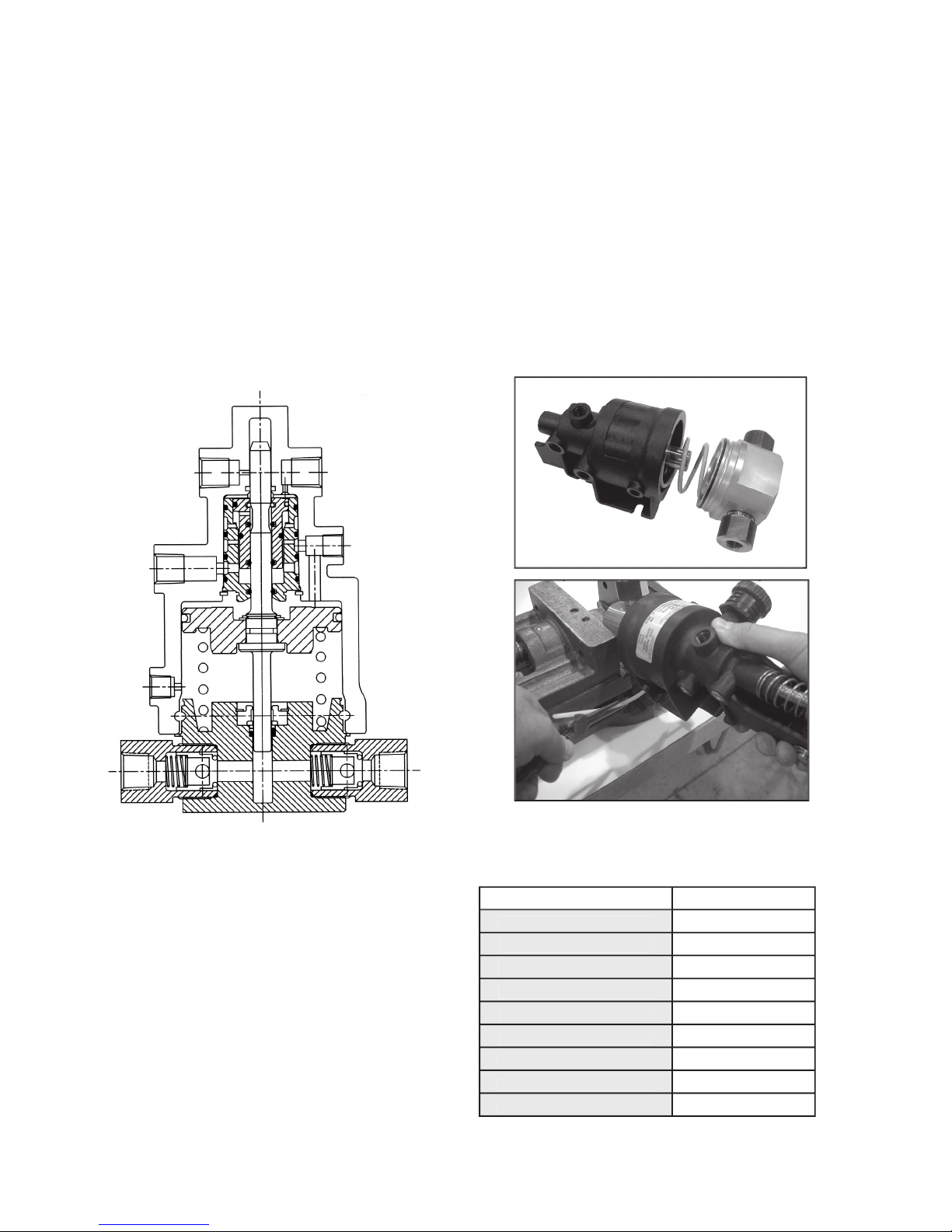
MINIPUMP ASSEMBLY
Lubricate the o-ring with “Accrolube” Te on grease or
equivalent. Use lubricants compatible with seal com-
pounds. Install the 91417-039 o-ring on the high pressure
body external o-ring groove. Fixture high pressure body in
a vise. Place spring, p/n 100776 in low pressure body, as-
semble low pressure body on the high pressure body. Use
care, the high pressure piston must enter the high pressure
seal. Also, the o-ring on the high pressure body engages
the low pressure body, do not cut the o-ring. Install the
retainer p/n 100173 in the entry hole on the forward part of
the low pressure body. Rotate low pressure body clock-
wise as you feed, (push) the retainer in. Install spirol pin,
100402, per assembly drawing.
The following kits are available to refurbish the low pres-
sure air module and high pressure modules as follows:
ASSEMBLY NUMBER
SERVICE KIT NUMBER
3A3S (Low pressure module)
3A3S-SK
3X – 005 (5:1 H.P. module)
3X-005-SK
3X – 010 (10: 1 H.P. module)
3X-010-SK
3X – 020 (20:1 H.P. Module)
3X-020-SK
3X – 035 (35:1 H.P. module)
3X-035-SK
3X – 060 (60:1 H.P. module)
3X-060-SK
3X – 100 (100:1 H.P. module)
3X-100-SK
3X – 150 (150:1 H.P. module)
3X-150-SK
3X – 225 (225:1 H.P. module)
3X-225-SK

15
Item
No.
Description
Part No.
Quantity
Quantities the Same as STD. Unit
3A-005
3S-005
3A-010
3S-010
3A-020
3S-020
3A-035
3S-035
-02 (NEO)
-03 (VIT)
-04 (EPR)
1
Body, H.P., -005, ALUM.
100700-005A
1
Body, H.P., -005, SST.
100700-005S
1
Body, H.P., -010, ALUM.
100704-010A
1
Body, H.P., -010, SST.
100704-010S
1
Body, H.P., -020, ALUM.
100704-020A
1
Body, H.P., -020, SST.
100704-020S
1
Body, H.P., -035, ALUM.
100704-035A
1
Body, H.P., -035, SST
100704-035S
1
2
Piston Shaft, -005
100746
1
Piston Shaft, -010
100747
1
Piston Shaft, -020
100750-020
1
Piston Shaft, -035
100750-035
1
3
Bearing, -005
100738
1
Bearing, -010
100739
1
Bearing, -020
100740
1
Bearing, -035
100741
1
4
Backup Ring, -005
100738-1
1
Backup Ring, -010
100739-1
1
Backup Ring, -020
100740-1
1
Backup Ring, -035
100741-1
1
5
Washer Bearing, -005
100738-2
1
Washer Bearing, -010
100739-2
1
Washer Bearing, -020
100740-2
1
Washer Bearing, -035
100741-2
1
6
Ring, Retaining, -005
100442
1
Ring, Retaining, -010
100443
1
Ratio
Ring, Retaining, -020
100444
1
Ring, Retaining, -035
100445
1
7
Seal, Lip, UHMWPE, -005
100376
1
100664 PTFE
005
Seal, Lip, UHMWPE, -010
100377
1
100665 PTFE
010
Seal, Lip, UHMWPE, -020
100378
1
100666 PTFE
020
Seal, Lip, UHMWPE, -035
100379
1
100667 PTFE
035
8
O-Ring, NIT., 70 SH., -005
91417-123
1
91417-123-11
91417-123-17
91417-123-26
005
O-Ring, NIT., 70 SH., -010
91417-118
1
91417-118-11
91417-118-17
91417-118-26
010
O-Ring, NIT., 70 SH., -020
91417-114
1
91417-114-11
91417-114-17
91417-114-26
020
O-Ring, NIT., 70 SH., -035
100821
1
100821-11
100821-17
100821-26
035
9
O-Ring, NIT., 90 SH.
91417-019-1
2
91417-019-24
91417-019-18
91417-019-28
10
Body, C.V., 3/8 NPT.
88906
11
Poppet, 3/8 NPT.
79420-1
12
O-Ring, NIT., 90 SH.
79550-8-1
79550-9-24
79550-8-18
79550-28
13
Spring, C.V.
S-216-23
Assembly Drawings and Parts Lists
SM3 HP (005-035)
RATIOS 5, 10, 20, & 35
RATIOS 5, 10, 20, & 35
Seal Detail
Outlet
Inlet
16
Item
No.
Description
Part No.
Quantity
Quantities Same as STD. Unit
3A-060
3S-060
-02 (NEO)
-03 (VIT)
-04 (EPR)
1
Body, H.P., -060, ALUM.
100704-060A
1
Body, H.P., -060, SST.
100704-060S
1
2
Piston Shaft, -060
100750-060
1
3
Bearing
100742
1
4
Backup Ring
100742-1
1
5
Washer Bearing
100742-2
1
6
Ring, Retaining
100446
1
7
Seal, Lip, UHMWPE
100660
1
100668 (PTFE)
8
O-Ring, NIT., 70 SH.
100820
1
100820-11
100820-17
100820-26
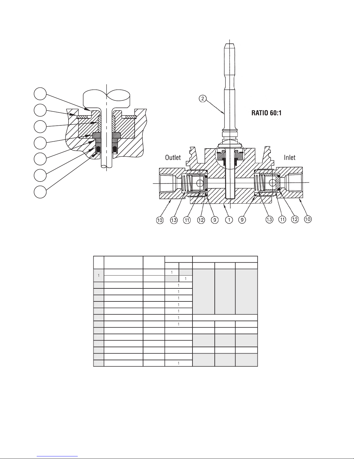
9
O-Ring, NIT., 90 SH.
91417-019-1
2
91417-019-24
9147-019-18
91417-019-28
10
Body, C.V., 3/8 NPT.
94056
2
11
Poppet, 3/8 NPT.
89297
2
12
O-Ring, NIT., 90 SH.
79550-15-1
2
79550-8-24
79550-8-18
91417-110-28
13
Spring, C.V.
S-216-63
2
14
Carrier, Bearing
100742-3
1
SM3 HP (060)
RATIO 60:1
Seal Detail
Outlet
Inlet
SM3 HP (100-225)
Item
No.
Description
Part No.
Quantity
1
Body, H.P., -100, ALUM.
100704-100A
1
Body, H.P., -100, SST.
100704-100S
1
Body, H.P., -150, SST.
100713-150
1
Body, H.P., -225, SST.
100713-225
1
2
Piston Shaft, -100
100750-100
1
Piston Shaft, -150
100750-150
1
Piston Shaft, -225
100750-225
1
3
Bearing, -100
100743-1
1
Bearing, -150
100744
1
Bearing, -225
100745
1
4
Backup Ring, -100
100743
1
Backup Ring, -150
100744-1
1
Backup Ring, -225
100745-1
1
5
Washer Bearing, -100
100743-3
1
Washer Bearing, -150
100744-2
1
Washer Bearing, -225
100745-2
1
6
Ring, Retaining, -100
100447
1
Ring, Retaining, -150, -225
100446
1
7
Seal, Lip, UHMWPE, -100
100661
1
Seal, Lip, UHMWPE,-150
100662
1
Seal, Lip, UHMWPE, -225
100663
1
8
O-Ring, NIT., 70 SH., -100
100325
1
O-Ring, NIT., 70 SH., -150
100324
1
O-Ring, NIT., 70 SH., -225
100323
1
9
Body, C.V., 9/16-18 UNF
89298-1
1
10
Spring, C.V.
S-216-63
2
11
Poppet, H.P., .400 ID/.495 OD.
89297
2
12
O-Ring, NIT., 90 SH.
79550-5-1
2
13
Gasket, CV, SS, .500 I.D.
S-216-28-8
1
14
Seat, CHK. VLV. for 82648
S-216-27-4
1
15
Body, C.V., H.P., 1/4 NPT
89298
1
16
Gasket, CV, SS, .250 I.D.
S-216-28-10
1
17
Carrier, Bearing
100743-2
1
Carrier, Bearing
100744-3
1
Carrier, Bearing
100745-3
1
RATIOS 100, 150, & 225
RATIOS 100, 150, & 225
Seal Detail
17
Outlet
Inlet
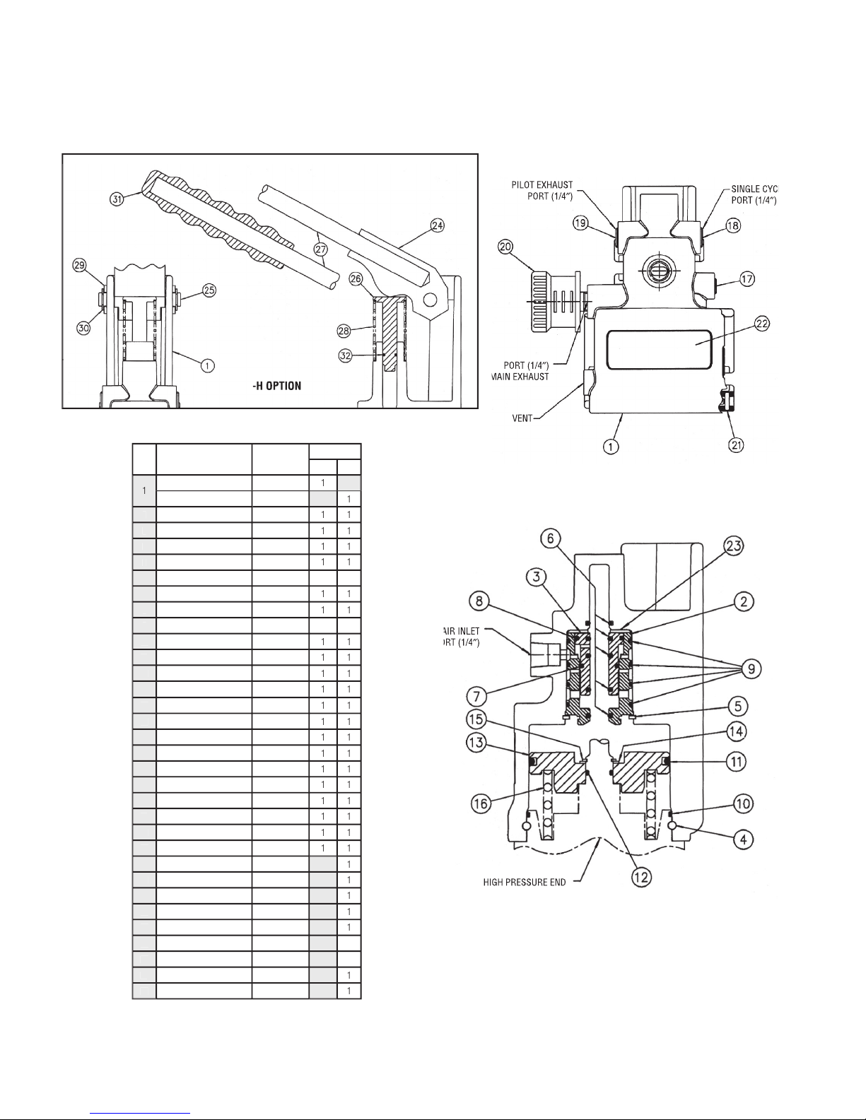
SM3 LP : Low Pressure Body Assembly
Item
No.
Description
Part No.
Quantity
3A3S
-H
1
Body, L.P., Air Motor, Std.
100777
1
Body, L.P., Air Motor, Hand
100778
1
2
Sleeve, Spool
100763
1
1
3
Spool
100764
1
1
4
Retainer
100173
1
1
5
Ring, Retaining
100441
1
1
6
O-Ring, 90 SH
91417-012-41
5
5
7
O-Ring, 80/90 SH
91417-017-29
1
1
8
O-Ring, 70/75 SH
91417-020
1
1
9
O-Ring, 70/75 SH
91417-025
3
3
10
O-Ring, 70 SH
91417-039
1
1
11
O-Ring, 80/90 SH
91417-231-29
1
1
12
O-Ring, 70 SH
91417-013
1
1
13
Piston, L.P.
100765
1
1
14
Washer
100754
1
1
15
Ring, Retaining
100880
1
1
16
Spring
100776
1
1
17
Plug, Pipe, 1/8 NPT.
93971-1
1
1
18
Plug, Pipe, 1/4 NPT.
93971-2
1
1
19
Plug, Vent, 1/4 NPT.
100186
1
1
20
Muf er
101021
1
1
21
Pin, Coiled, Spirol
100402
1
1
22
O-Ring 70/75 SH
80063-2
1
1
23
Washer, Spool
100799
1
1
24
Handle, Lever, Bracket
100771
1
25
Pin, Hinge
100757
1
26
Spigot, Handle, Return
100756
1
27
Rod, Handle
100758
1
28
Spring
100508
1
29
Washer
100482
2
30
Ring, Retaining
100900
2
31
Grip, Handle
100920
1
32
O-Ring, 80/90 SH
100810
1
18
-H OPTION
MAIN AIR INLET
MAIN AIR INLET
PORT (1/4
PORT (1/4
″
)
HIGH PRESSURE END
VENT
PORT (1/4
″
)
MAIN EXHAUST
MAIN EXHAUST
PILOT EXHAUST
PORT (1/4
″
)
SINGLE CYCLE
SINGLE CYCLE
PORT (1/4
″
)
STANDARD SUPPLY


© Sprague Products 2004
SM3 5M 304
Sprague Products
Division of Cur
tiss-
Wr
ight Flow Control Corporation
10195 Brecksville Road
10195 Brecksville Road
Brecksville, OH 44141 USA
Telephone: 440-838-7690 • Fax: 440-838-7513
www.cwfc.com
Sprague Products U.K.
Sprague Products U.K.
202 St. Andrews Road
Bridport, Dorset DT6 3B6
Table of contents


