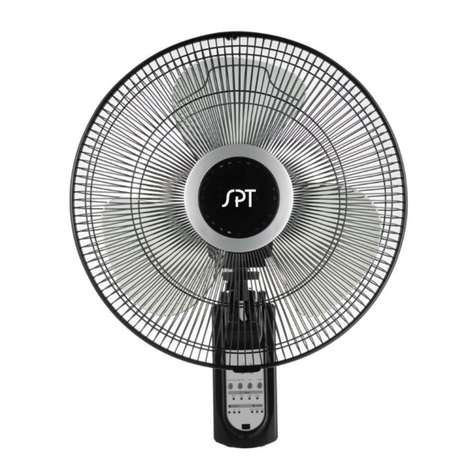
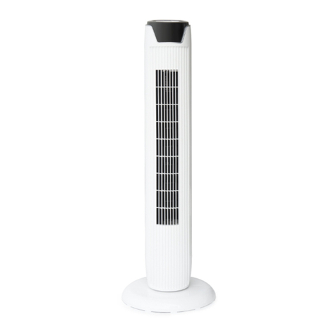
SPT SF-16W90 User manual

OWNER’S MANUAL
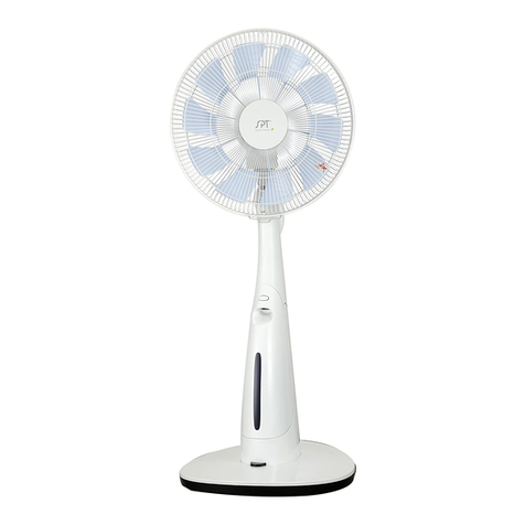
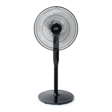
16" Wall Fan
MODEL: SF-16W90
READ AND SAVE THESE INSTRUCTIONS
Attention: Pictures in the IM are for reference only.
R

IMPORTANT SAFEGUARDS
Read Rules for Safe Operation and Instructions Carefully.
Caution
1. If the supply cord is damaged, it must be replaced by manufac-
turer or its service agent or a similarly qualified person in order
to avoid a hazard.
2. To protect against the risk of electrical shock, do not immerse
the unit, cord or plug in water or other liquid.
3. This appliance is not intended for use by persons (including
children) with reduced physical, sensory or mental capabilities,
or lack of experience and knowledge, unless they have been
given supervision or instruction concerning use of the appli-
ance by a person responsible for their safety. Young children
should be supervised to ensure that they do not play with the
appliance.
4. When the appliance is not in use and before cleaning, unplug
the appliance from the outlet.
5. Keep electrical appliances out of reach from children or infirm
persons. Do not let them use the appliances without supervi-
sion.
6. When the fan was assembled, the rotor blade guard shall not
be taken off anymore
• Prior cleaning unplug the fan.
• The rotor guard shall not be dissembled/opened to clean the
rotor blades.
• Wipe the fan enclosure and rotor blade guard with a slightly
damp cloth.
WARNING
1

7. WARNING: To Reduce The Risk Of Fire Or Electric Shock, Do
Not Use This Fan With Any Solid-State Speed Control Device.
8. This product employs overload protection (fuse). A blown fuse
indicates an overload or short-circuit situation. If the fuse
blows, unplug the product from the outlet. Replace the fuse by
following the instructions at Page 9. and check the product.
If the replacement fuse blows, a short-circuit may be present
and the product should be discarded or returned to an
authorized service facility for examination and/or repair.
9. Do not operate any fan with a damaged cord or plug. Discard
fan or return to an authorized service facility for examination
and/or repair.
10.Do not run cord under carpeting. Do not cover cord with throw
rugs, runners, or similar coverings. Do not route cord under
furniture or appliances. Arrange cord away from traffic area and
where it will not be tripped over.
11.This appliance has a polarized plug (one blade is wider than
the other). To reduce the risk of electric shock, this plug is
intended to fit in a polarized outlet only one way. If the plug
does not fit fully in the outlet, reverse the plug. If it still does not
fit, contact a qualified electrician. Do not attempt to defeat this
safety feature.
12.Do not remove the motor cover for repair or other purposes.
WARNING
2

8
13
4
2
5 6 7
RULES FOR SAFE OPERATION
1. Never insert fingers, pencils, or any other object through the
grille when fan is running.
2. Disconnect fan when moving from one location to another.
3. Be sure fan is on a stable surface when operating to avoid
overturning.
4. Use your fan only in dry environments. This fan is not intended
for use in a bathroom, laundry area, or similar locations, or
near sinks, washing machines, swimming pools or other
sources of water. Never locate fan where it may fall into a
bathtub or other water receptacle. Do not use in damp
environments such as flooded basements.
5. Household use only.
PART FIGURE
NO. Description NO. Description
1 Front Grill
2 Spinner
3 Fan blade
5 Rear Grill
4 Plastic lock nut
6 Motor Shaft
7 Motor and motor cover
8 Control panel
3

Clip
PART FIGURE
All the pictures in this manual are for explanation purpose only. Any discrepan-
cy between the real object and the illustration in the drawing shall be subject to
the real product.
Note:
GRILL & FAN BLADE ASSEMBLY
1. Unscrew the spinner clockwise (or take the spinner
out from the bag) and the plastic nut counterclockwise
to remove both of them. Fix the rear grill to the motor
then tighten the plastic nut again. (Fig. 1)
2. Insert the blade into shaft, and make sure the motor
shaft pin is fitted into groove of the blade. Turn the
spinner counterclockwise to tighten the blade. (Fig. 2)
3. Fasten the front grill and the rear grill by the grill clip
and then tighten the fan grill locking screw and nut.
(Fig. 3)
Fig.1
Fig.2
Fig.3
4

•
“ ” ON/OFF KEY
The key is for switching on the fan .The fan will be started at
low speed.Press this key again, and the fan will be switched off.
REMOTE CONTROLLER OPERATION
To prevent the fan from falling off, do not install it on walls less then 4 inches
thick or made of materials that are easily damaged.
Caution
The bracket should be placed at least 12 inches below the ceiling and at least 12
inches from adjoining wall.
Note:
INSTALLATION INSTRUCTIONS
MOUNTING ON THE WALL
The fan should be installed on a solid wooden or
pillar which stands vertically to the floor.
1.Installing the mounting bracket
Fix the supplied mounting bracket firmly to the wall using the
two screws.
2.Installing the stand
Mount the stand on the bracket by inserting the
bracket catch into the slot on the stand.
TO ADJUST THE WIND DIRECTION
Push the guard lightly to the desired up or down direction.
OPERATING INSTRUCTIONS
5

OPERATING INSTRUCTIONS
6
•
“ ” SPEED KEY
•
“ ” OSC KEY
After the fan is started, press this key to oscillate the fan, and stop the oscillation at
desired direction by pressing the key again.
•
“ ” TIMER KEY
To adjust the air flow upward or downward, hold and move the fan grills gently to the
desired direction.
Tilt Adjustment
•
“ ” MODE KEY
Press this key to select mode. This key is a selector key for wind type. The wind type
changes in the sequence of NORMAL---NATURAL---SLEEP---NORMAL---
NATURAL wind when this key being pressed repeatedly .
The features of 3 wind types are as followed:
NORMAL WIND:
The fan delivers air constantly with high, medium or low speed set by the SPEED key.
NATURAL WIND:
The fan delivers air based on a preset program that simulates natural wind.
SLEEP WIND:
The fan will drop the speed level by level and then turns itself off automatically at
the end.
Press the TIMER key, each time it is pressed, time duration indicator lights
illuminate. (0.5, 1, 2 or 4 hours). Simply add up the time value of the lights to see
timer setting up to 7.5 hours maximum time.
To turn the timer function off, press the TIMER key continuously until all the timer
indicator lights are off.
Example: If you want to set the timer for 5.5 hours, this key must be pressed
repeatedly until the indicator lights of 0.5, 1 and 4 hours are on all together. It
means that the set timer is 0.5 + 1+ 4= 5.5 hours.
The timer setting indicated by the indicator lights will decrease gradually by a unit
of 0.5 hour.
After the fan has started, press to change fan speed in sequence of: Low - Medium
- High. The corresponding indicator light will illuminate on the control panel.

OPERATING INSTRUCTIONS
7
CONTROL PANEL
“SPEED ON/OFF” button
Press this button once to switch fan on. Continue pressing to select speed
in sequence: Low - Medium - High.
The corresponding speed indicator will illuminate.After cycling through the
modes, press again to turn off.
“MODE” button
Same function as the remote
“OSC” button
Same function as the remote
“TIMER” button
Same function as the remote
CONTROL PANEL OPERATTON

OPERATING INSTRUCTIONS
AAA Battery, 1.5v
Use manganese or alkaline
batteries of type "AAA". Do not
use rechargeable batteries.
BATTERIES INSTRUCTIONS
(not included)
1. Press down on the battery compartment cover and slide it out.
2. Insert the batteries, making sure that the positive terminals are facing the
proper way.
3. Replace the cover.
Note:
Use manganese or alkaline batteries of type "AAA".
Do not use rechargeable batteries.
1. Do not dispose of batteries in fire, batteries may
explode or leak.
2. Do not mix old and new batteries.
3. Do not mix alkaline, standard (carbon-zinc) or
rechargeable (nickel-cadmium) batteries.
BATTERY WARNING
8

OVERHEAT PROTECTION OF THE MOTOR
HOW TO USE THE REMOTE CONTROLLER CORRECTLY
Point the remote controller at the receptor on the control panel of the fan and press
the desired button. The remote controller will work at distance of up to roughly 16
feet and the angle of 30 degrees to the left or right and left from the receptor.
A thermal fuse is installed in the motor that will prevent the motor from overheating
due to any unexpected reasons.
The fan requires little maintenance. Do not try to fix it by yourself. Refer it to
qualified service personnel if service is needed.
1. Before cleaning and assembling, fan must be unplugged.
2. To ensure adequate air circulation to the motor, keep vents at the rear of the
motor free of dust. Do not disassemble the fan to remove dust.
3. Please wipe the exterior parts with soft cloth with mild detergent.
4. Do not use any abrasive detergent or solvents to avoid scratching the surface.
Do not use any of the following as a cleaner: gasoline, thinner.
5. Do not allow water or any other liquid into the motor housing or interior parts.
MAINTENANCE INSTRUCTION
CLEANING
9
1. Be sure to unplug from the electrical supply source before cleaning.
2. Plastic parts can be cleaned with mild soap and a damp cloth or sponge.
Follow with clean damp towel to remove soap film.
3. Be sure water or other liquid does not come in contact with the motor.

10
FUSE REPLACEMENT
a) Grasp plug to remove from the receptacle. Do not unplug by pulling on
the cord.
b) Fuse is located on the plug. Slide the fuse cover towards the blades to
open. (Fig. )
c) Remove fuse carefully. Using a tweezer, insert the tip of your tool into the fuse
slot and grasp one end. Remove the fuse gradually and slowly - do not overexert.
If it feels tight, wiggle gently to remove little by little. When one side of the fuse has
come loose, you can remove the fuse entirely. (Fig. )
d) Risk of fire. Replace fuse only with 2.5 Amp, 125 Volt fuse. (Fig. )
e) Slide close the fuse access cover. (Fig. )
f) Risk of fire. Do not replace attachment plug. It contains a safety device (fuse)
that should not be removed. Discard product if the attachment plug is damaged.
Notice:
• 1. When replacing the fuse, do not overexert or product may be damaged.
• 2. If it seems too hard to install, make sure you have got the right fuse type.
1 2 3 4
1
2
3
4

11
Your Guarantee
SUNPENTOWN
If this product is found to be faulty as a result of faulty materials or workmanship
within one year from date of purchase, it will be repaired free of charge.
This guarantee is subject to the following terms:
• Sunpentown must be notified of the fault.
• Proof of purchase must be presented to Sunpentown’s nominated representa-
tive.
• The warranty will be void if the product if modified, misused or repaired by an
unauthorized person.
• The warranty after repair will not be extended beyond the original one-year
period.
• All replacement parts will be new or reconditioned.
• Parts, which are replaced, become the property of Sunpentown.
• The warranty applies for the use of the product in the USA only.
What is NOT COVERED:
• Warranty does not include freight charges.
• Incidental or consequential damage caused by possible defects with this
product.
• Damage to product caused by improper power supply voltage, accident, fire,
floods or acts of nature.
• Failure of product resulting from unauthorized modifications to the product.
• Improper installation or failure to perform the necessary maintenance.
This GUARANTEE is in addition to your Statutory Rights
SUNPENTOWN INTERNATIONAL INC.
14625 Clark Ave, City of Industry, CA 91745
Tel: 800-330-0388
service@sunpentown.com
www.sunpentown.com
Table of contents
Other SPT Fan manuals
Popular Fan manuals by other brands

Titus
Titus DVCP Installation and operation manual

Greenheck
Greenheck GreenJet GJI Installation, operation and maintenance manual

Greenheck
Greenheck FDR-510 Specification sheet

TURNTIDE
TURNTIDE VES-Artex ECVD72 install guide

RenewAire
RenewAire DN-Series Installation, operation and maintenance manual

Rosenberg
Rosenberg ERAD E Series Operating instruction