squarespace SMART CELLAR Installation guide

SMART CELLAR INVERTER COOLING UNIT
WWW.AIRSHEPHERD.COM.AU
CONTENTS
1 SAFETY WARNINGS AND PRECAUTIONS
2 OPERATION AND MAINTENANCE
3 SMART CELLAR QUICK REFERENCE GUIDE
4 INDOOR INSTALLATION GUIDE
14 INDOOR LCD AP2 GATEWAY DIAGNOSTICS
15 TROUBLESHOOTING
16 INDOOR AND OUTDOOR ELECTRICAL WIRING DIAGRAM
19 OUTDOOR UNIT INSTALLATION
24 REFRIGERATION LINE SET AND CONNECTION INSTRUCTIONS
29 REFRIGERANT CHARGING
30 INDOOR LCD AP2 GATEWAY ERROR CODE LIST
34 END
WWW.AIRSHEPHERD.COM.AU0

SMART CELLAR INVERTER COOLING UNIT
SAFETY WARNINGS AND PRECAUTIONS
This appliance is not intended for use by persons (including children) with reduced physical, sensory
or mental capabilities, or lack of experience and knowledge, unless they have been given supervision
or instruction concerning use of the appliance by a person responsible for their safety.
●Children should be supervised to ensure that they do not play with the appliance.
●Please read this manual carefully before operating the unit and keep it in a safe location for
future reference.
●Installation or maintenance should always be conducted by an authorized dealer or local
service centre.
●Only use the SMART CELLAR as instructed in this booklet. These instructions are not
intended to cover every possible condition and situation. As with any electrical household
appliance, common sense and caution are therefore always recommended for installation,
operation and maintenance.
This marking indicates that this product should not be disposed of with other household
wastes throughout Australia. To prevent possible harm to the environment or human health
from uncontrolled waste disposal, recycle it responsibly to promote the sustainable reuse of
material resources. To return your used device please use the return and collection systems
or contact the retailer where the product was purchased. They can take this product for
environmentally safe recycling.
The design and specifications here within are subject to change without notice for product
improvement. Please consult with Customer Service for further details.
Applicable AIR SHEPHERD to SMART CELLAR INVERTER COOLING UNIT
SAFETY PRECAUTIONS
Explanation
DANGER Indicates a hazardous situation that, if not avoided, will result in death or serious injury.
WARNING Indicates a hazardous situation that, if not avoided, could result in death or serious injury.
CAUTION Indicates a hazardous situation that, if not avoided, may result in minor or moderate injury.
NOTICE Indicates important but not hazard-related information, used to indicate risk of property
damage.
WWW.AIRSHEPHERD.COM.AU
1

SMART CELLAR INVERTER COOLING UNIT
OPERATION AND MAINTENANCE
●Always disconnect power supply when cleaning the SMART CELLAR, to minimise the risk of
electric shock, injury or damage to the appliance.
●Never install or operate SMART CELLAR with a damaged supply cord. This must be replaced
by the qualified persons to avoid a hazard.
●Never wash SMART CELLAR with water, as this may cause electric shock, injury or damage
to the appliance.
●Maintenance must always be performed by qualified personnel. Never attempt to repair the
SMART CELLAR yourself, as this may cause electric shock, injury or damage. Please contact
AIR SHEPHERD or an authorised service provider for all repairs and maintenance.
●Do not extend fingers or objects into the air inlet or air outlet, as this may cause personal
injury or damage.
●Do not block the air outlet or air inlet, as this may cause damage or malfunction, or affect
performance of the unit.
●If the following occurs, please turn off SMART CELLAR and disconnect power immediately,
and contact AIR SHEPHERD, the dealer or a qualified professional for service.
○Power cord is overheating or damaged.
○There is an abnormal sound during operation.
○Circuit breaker trips frequently.
○SMART CELLAR gives off a burning smell.
○Indoor unit is leaking.
●If the SMART CELLAR operates under abnormal conditions, it may cause a malfunction,
electric shock or a fire hazard.
●Never use a metal object when turning the indoor unit on or off by the emergency operation
switch, as this may cause electric shock or injury.
●Never step on the top panel of the outdoor unit or place heavy objects on it, as this may
cause damage or personal injury.
WWW.AIRSHEPHERD.COM.AU
2

SMART CELLAR INVERTER COOLING UNIT
SMART CELLAR SPECIFICATIONS
WWW.AIRSHEPHERD.COM.AU
3

SMART CELLAR INVERTER COOLING UNIT
INSTALLATION
●Installation must be performed by qualified professionals. Otherwise, it may cause personal
injury or damage.
●The SMART CELLAR must be installed in accordance with national and local wiring
regulations, codes and standards.
●An all-pole disconnection switch having a contact separation of at least 3mm in all poles
should be connected in the fixed wiring.
●Always ensure the power supply matches with the nameplate of the SMART CELLAR.
Unstable power supply or incorrect wiring will cause malfunction. Always install the correct
power supply cables before operating the SMART CELLAR.
●Always disconnect the power supply before proceeding with any work on the SMART
CELLAR.
●Do not supply power to the unit before finishing installation.
●Never install or operate SMART CELLAR with a damaged power supply cable. This must be
replaced by the manufacturer, its service agent or similarly qualified persons to avoid a
hazard.
●The temperature of the refrigerant circuit will be high, always keep the interconnection cable
away from the copper tube.
●The SMART CELLAR is a Class 1 electric appliance. It must be properly earthed using a
specialised earthing device installed by a professional, otherwise it may cause electric shock.
WWW.AIRSHEPHERD.COM.AU
4

SMART CELLAR INVERTER COOLING UNIT
●The yellow-green wire in SMART CELLAR is the earth wire. The earth wire cannot be used
for other purposes.
●The earthing resistance should comply with national and local electrical safety regulations,
codes and standards.
●The indoor unit and outdoor unit must be connected by a qualified professional.
●SMART CELLAR must be installed by qualified tradespersons with written proof of installation
and compliance certifications for AIR SHEPHERD to act on warranty claims for repairs.
5
SPACE REQUIREMENTS
●Accessibility to the SMART CELLAR ultra compact indoor unit is required to perform servicing
and repairs if required is the sole responsibility of the installer and owner of the property.
●AIR SHEPHERD is not responsible for unit location accessibility for relevant required repairs
if necessary under manufacturer's warranty period. This is the responsibility of the end user/
installer.
INSTALLATION OPTIONS
A. Instillation of the indoor unit
●The SMART CELLAR ultra compact indoor unit can be concealed ceiling space as a ducted
unit.
●The SMART CELLAR ultra compact indoor unit can be concealed in underfloor spaces
(subfloor) as a ducted unit.
●The SMART CELLAR ultra compact indoor unit can be concealed in a bulkhead as a
bulkhead unit.
●The SMART CELLAR ultra compact indoor unit can be Under ceiling mounted (exposed)
B.. Installation of the Indoor Unit
1. Drill hole suitable for the M10 expansion bolt. Insert the M10 expansion bolt into the hole, and
then knock the nail into the bolt. Refer to the drawings for the distance between holes and
see Figure 3 for the installation of the expansion bolt.
Figure 3: Installation of the Expansion Bolt
WWW.AIRSHEPHERD.COM.AU
5

SMART CELLAR INVERTER COOLING UNIT
2. Install the hanger on the indoor unit, as shown in Figure 4.
Figure: 4
1. Prior to installation, prepare all piping (refrigerant pipe, drain pipe) and wiring (wired
controller, wires between the indoor and outdoor unit) of the indoor unit
2. Reinforce ceiling openings to reduce vibration and noise transmission. Consult a qualified
tradesperson for advice.
3. If the ceiling or structure cannot support the unit, the unit may need to be mounted on
brackets to suit the installation. Fabrication of the brackets shall be by others.
4. If the indoor unit is not installed in the conditioned space, the unit must be insulated to
prevent condensation.
Figure 5: Installing the Indoor Unit
WWW.AIRSHEPHERD.COM.AU
6

SMART CELLAR INVERTER COOLING UNIT
Check Indoor Unit is Level
●Low humidity environment - insure unit is level without fall to drain port, this will keep 3-5mm
of condensate in evaporator drip tray.This will increase relative humidity
●Supplied Indoor Installation bag contains one large foam adhesive rectangular strip that can
be installed into the base only of the evaporator drip tray to increase humidity level.
●High humidity environment - Adjust the mounting bolts so the unit is secure and level. Adjust
the unit so it has an inclination of 5° downwards towards the drain pipe, and is horizontal, as
shown in Figure 6.
Figure 6: Levelling the Indoor Unit
Figure 6:
Installation Of The Supply Air And Return Air Ducts
Figure 7: Arrangement for Rectangular Air Supply Ducting
*
Figue:7
1
2
3
4
5
6
Return air
louver
Flexible
connect
Return air
duct
Indoor unit
Supply air
duct
Access grille
WWW.AIRSHEPHERD.COM.AU
7

SMART CELLAR INVERTER COOLING UNIT
Figure 8
1
1. Preinstall the outlet of the round duct on the transition duct and then fix it with self-tapping
screws.
2. Insert the transition duct onto the air outlet of the unit and fix it with rivets.
3. Connect the outlet to the duct and seal all joins with tape. Other installation details are not
covered herein.
CAUTION
1. The maximum length of the duct is 24m, equals the maximum length of the air supply duct
plus the maximum length of the return air duct.
2. Supply air flex duct size - 12’ (300MM)
3. Return air flex duct size - 14’ (350mm)
4. If a round duct is used on units fitted with an auxiliary electric heating function, the straight
length of the transition duct cannot be less than 200mm.
5. At least one air supply grille shall be permanently open.
6. At least one return grille shall be permanently open.
1
2
3
4
5
6
7
8
9
Plenum
return
air
Return
air duct
Canvas
duct
Return
air
louver
Supply
air
outlet
Plenum
supply
Supply
air duct
diffuser
Diffuser
joint
WWW.AIRSHEPHERD.COM.AU
8

SMART CELLAR INVERTER COOLING UNIT
Installation of the Condensate Pipe
1. The condensate pipe should be installed at an angle of 5 - 10° to facilitate the drainage of
condensate water from the unit. The condensate pipe should be insulated to minimise condensation
(See Figure 13).
Figure 13: Thermal Insulation of the Condensate Pipe
2. The unit is fitted with a condensate outlet on both the left and right sides of the unit, to aid in
installation. Only one drain should be used and the other should be blanked off, sealed and
covered with insulation to avoid water leakage.
3. The right outlet is blanked off by default.
CAUTION
• Condensate pipe joins should be checked and sealed to prevent water leakage.
Condensate Drain Pipe Design and Installation
1. !"#$%&'(#)#*$+,$)"#$%*'&-$.&.#$/"+01%$2#$1'*3#*$+*$#40'1$)+$)"')$+,$)"#$*#,*&3#*'-)$.&.#$5678$
.&.#9$+0)#*$%&'(#)#*:$;<((9$='11$)"&>?-#//$@AB<((CB
2. The drain pipe should be as short as possible.
3. The drain pipe should be maintained at an angle of 1/50 ~1/100 to avoid water becoming
trapped or air pockets forming.
4. If sufficient angle cannot be provided, a lift pipe should be installed.
5. A maximum distance of 1-1.5m should be kept between the hangers to avoid the drain hose
sagging (see Figure 14).
6. Do not use excessive force when connecting the drain pipe to the unit. The end of the pipe
should be fixed as close as possible to the side of the unit.
7. The drain pipe is not supplied with the unit and should be provided by others. Slide the end of
the PVC pipe over the drain outlet and secure it with a hose clamp. Never connect the drain
pipe to the outlet by adhesive. (See Figure 15)
WWW.AIRSHEPHERD.COM.AU
9

SMART CELLAR INVERTER COOLING UNIT
8. When a single drain pipe is used for multiple devices, the common section of the pipe should
be 100mm lower than the drain hole of each device and should be sized appropriately for the
total water flow.
9. Condensate drains located in the air-conditioned space should be insulated to prevent water
damage.
Correct - With a minimum degree of slope 1/100 Incorrect
Precautions when Installing a Lift Pipe
●A lift pipe should be used in situations where a sufficient fall cannot be provided for a
standard condensate drain connection.
●The installation height of the lift pipe should be less than 850mm. It is recommended to set an
inclination angle 1° - 2° for the lift pipe toward the drainage direction. If the lift pipe and the
unit form a right angle, the height of the lift pipe must be less than 800mm.
WWW.AIRSHEPHERD.COM.AU
10

SMART CELLAR INVERTER COOLING UNIT
NOTICE:
●Maximum lift of lift pipe (condensate pump) is 1m (1000mm) from base of unit.
●To prevent excessive force on the unit drain outlet, the drain hose connection between the lift
pipe and the drain pipe should not be misaligned by more than 75mm (See Figure 17).
●If multiple drain pipes are joined to a single drain pipe, the pipe shall be installed.
Testing the Drainage System
1. The drainage system on the unit should be tested prior to operation.
2. During the test, check to ensure the water flow goes through the pipe correctly and ensure
the joints do not leak. If a unit is installed in new construction, it is suggested the test is
carried out prior to the ceiling being fitted.
Installation of the Refrigerant Piping
1. Refrigerant pipe installation and testing shall be carried out by a qualified technician in
accordance with appropriate standards and codes.
2. Use thread sealant.
3. Align the flared end of the copper pipe point with the threaded pipe on the unit and tighten the
screw by hand.
4. Use a torque wrench to tighten the joint in accordance with general torque specifications for
size piping.
Insulation for the Refrigerant Pipe
1. The refrigerant pipe should be insulated to prevent condensation.
2. The joints of the indoor unit should be wrapped with the insulating material and ensure there
is no gap between the insulation and the indoor unit.
3. Wrapping the pipe with tape.
●Wrap the pipe from the bottom of the outdoor unit to the top of the pipe where it enters the
wall.
●Fix the wrapped pipe on the wall with clamps.
CAUTION
●Do not wrap the pipe too tightly; otherwise the insulation effect will be reduced.
●Make sure the drain hose is separated from the refrigerant pipe
●Seal the wall penetration to prevent wind and rain ingress.
WWW.AIRSHEPHERD.COM.AU
11

SMART CELLAR INVERTER COOLING UNIT
Connection to the Wiring Terminal
WARNING All electrical work must be carried out by a licensed electrician. a. Single-Core Wire
1. Strip 25mm of the insulating layer at the end of the wire with a wire stripper.
2. Loosen the screw on the wiring board of the SMART CELLAR unit.
3. Use pliers to shape the end of the wire to a circle matching the size of the screw.
4. Insert the screw through the wire and then fix it to the wiring board.
b. Multi-Core Wire
1. Strip 10mm of the insulating layer at the end of the wire with a wire stripper.
2. Loosen the screw on the wiring board of the air conditioning unit.
3. Fix a wiring terminal matching the size of the screw to the end of the multi-core wire with
crimping pliers.
4. Insert the screw through the terminal of the multi-core wire and then fix it to the wiring board.
WARNING
●If the power cable or the signal line is damaged, they must be replaced with a new cable.
●Prior to wiring, check the voltage marked on the nameplate is correct and then follow the
wiring diagram.
●The dedicated power cable must be used for the SMART CELLAR ultra compact indoor unit.
The unit must be fitted with a current leakage protection switch and air switch in case of unit
overload.
●The SMART CELLAR ultra compact indoor unit must be earthed.
●Wiring terminals or single-core wire must be used. Direct wiring between multi-core wires and
the wiring board may cause fire.
●The unit must be wired in accordance with the wiring diagram. Incorrect wiring may result in
the SMART CELLAR ultra compact indoor unit running abnormally or damage to the unit.
●Do not let electrical wires touch the refrigerant pipe, the compressor, the fan or other moving
parts.
●Do not modify the wiring inside the indoor unit. Doing so will void the warranty.
●Communication cable from indoor unit ( N.2 on terminal strip) must be wired to smart cellar
gateway module, communication cable from smart cellar gateway terminal (N.2) must be
connected to communication cable to outdoor unit terminal N.2
21Wiring of the Power Cable (Single Phase)
WWW.AIRSHEPHERD.COM.AU
12

SMART CELLAR INVERTER COOLING UNIT
CAUTION
• SMART CELLAR ultra compact indoor unit and SMART CELLAR inverter outdoor unit must be
installed on the same circuit breaker.
1. Remove the cover of the electric box of the indoor unit.
2. Insert the power cable through the rubber ring.
3. Connect the wiring (communication) through the piping hole of the chassis and upward
through the bottom of the appliance
4. Connect the brown wire to the Terminal board “3”; black wire (the communication wire) to the
Terminal board “2”; blue wire to the Terminal board “N(1)”,and connect the earthing wire to the
screw terminal on the electric box. Clamp them with the corresponding wire clamp packed in
the chassis.
5. Fix the power cable tightly with the binding wire.
6. Connect transformer interface cable to mains power supply at indoor unit location.
Wiring Of The Field Supplied 24V Thermostat And Communication Cable From Outdoor Unit
●Wall mount your smart thermostat
●Connect corresponding terminals from your smart thermostat to SMART CELLAR ULTRA
COMPACT indoor unit 24V terminal strip
●Power on SMART CELLAR system
●Set up your smart thermostat according to the manufacturer's instructions.
●After your smart thermostat is powered up, Select cool mode and adjust your set point
temperature.
SMART
CELLAR
R +24V AC
C - 24V AC
Y1 COOL/
COMP
Y2 COOL/
COMP
WWW.AIRSHEPHERD.COM.AU
13

SMART CELLAR INVERTER COOLING UNIT
Cellar Conditions Levels In Wine Cellars
●Every cellar is unique in the way it withholds heat and moisture levels.
●This in turn will result in your base Relative humidity level without cellar conditioning.
●Higher heat loads require longer run time for cooling which removes humidity from the air.
●The use of an independent room humidifier may be required for long term storage for cork
bottles.
●Recommended storage temperature range is between 12℃-18℃
●Relative humidity range between 50%-75%
SMART CELLAR AP2 GATEWAY LCD DIAGNOSTICS
●LCD diagnostic gateway display at indoor unit must be accessible for diagnostics and
fault diagnosis.
WWW.AIRSHEPHERD.COM.AU
14

SMART CELLAR INVERTER COOLING UNIT
TROUBLESHOOTING
NOTICE Performance issues
●If the SMART CELLAR unit operates abnormally, please check the following items before
contacting an authorised service agent.
●If the desired room temperature is not meeting demand, ensure the smart room thermostat is
working properly and calling for cooling (this is not an AIR SHEPHERD product)
●If the desired room temperature is not meeting demand, get in contact with us at
www.airshepherd.com.au to raise a warranty request via our website.
Note: installer of SMART CELLAR equipment must attend job address to assess equipment
status to eliminate installation errors for the full warranty period
AIR SHEPHERD warranty does not cover
●Installation errors.
●Defects in installation materials by others.
●Equipment that has not been correctly commissioned.
●Lifting equipment including crane lift services for equipment in the case of unit
replacement.
●Power supply issues to equipment
●Acts of God.
●Any product that is not supplied by AIR SHEPHERD.
Monthly Maintenance
a. Cleaning return air filter if required.
1. When the SMART CELLAR ultra compact indoor unit is used in a high dust environment, a
minimal restrictive air filter should be installed in the return air line and cleaned often
(generally once every 4 weeks with soapy water).
Note: failure to clean return air filter will cause:
●Poor supply air flow.
●Poor cooling performance
●Excessive electricity consumption
●Unit stop working (fault code)
b. Maintenance
1. Check if the air inlet/outlet of the indoor unit is unrestricted.
2. Check the earthing is in good condition.
3. Check the wiring is in good condition.
4. Check the indicating lamp of the LCD diagnostic display blinks after it is energised.
27
WWW.AIRSHEPHERD.COM.AU
15

SMART CELLAR INVERTER COOLING UNIT
Electrical Wiring
INDOOR & OUTDOOR UNIT WIRING DIAGRAM
CAUTION
●The installation must be conducted in accordance with local and national wiring regulations,
codes and standards.
●Only the power cord with the rated voltage and specified circuit for SMART CELLAR can be
used.
●Do not apply excessive force to the power cord.
●The electrical installation should be carried out by the technician as instructed by the local
and national regulations, codes and standards. This manual should be followed.
●Always replace a damaged power cord with the equivalent specified cord.
●Always ensure the unit is correctly earthed and the earth wire is connected to the dedicated
device of the building by the technician. Select the air switch coupled with the leakage current
protection switch to meet capacity, magnetic and thermal tripping functions in the event of a
short circuit and overload.
WWW.AIRSHEPHERD.COM.AU
16

SMART CELLAR INVERTER COOLING UNIT
Earthing Requirements
The SMART CELLAR is classified a Class I appliance and must be earthed.
The yellow-green wire is the earth line and cannot be: used for any other purpose, cut off, or fixed by
a self-tapping screw. Incorrect installation causes electrical hazards including electric shock or death.
A suitable earth terminal should be provided, and the earth wire must not be connected to any of the
following places:
●Potable water pipes;
●Gas pipes;
●Sewage pipes;
●Telecommunications earth wires
●A thermal-magnetic air switch circuit breaker of suitable capacity should be installed in
accordance with national wiring regulations to protect against short circuit and overload.
●The following capacity circuit breakers shall be used as listed in Table 2
Table 2: Circuit Breaker Capacity
Model: SMART CELLAR
Circuit Breaker Capacity 10A - 40A
3.4. Additional Safety Precautions Prior to Installation
WARNING
●When installing or relocating the unit, be sure to keep the refrigerant circuit free from air or
substances other than the specified refrigerant.
●Any presence of air or other foreign substance in the refrigerant circuit will cause an increase
in system pressure or compressor rupture, which may in turn result in personal injury or
property damage.
●When installing or relocating the unit, do not charge the unit with a refrigerant that does not
comply with that listed on the nameplate.
●Unapproved refrigerants may cause abnormal operation, incorrect actions, mechanical
malfunction or serious safety incidents, which may in turn result in personal injury or property
damage.
●When refrigerant needs to be recovered during installation, relocation or repair of the unit,
ensure the unit is running in cooling mode.
●Fully close the valve at the high pressure side (liquid valve).
●After approximately 45 seconds, fully close the valve at the low pressure side (gas valve)
●Immediately stop the unit and disconnect the power.
●The time for refrigerant recovery should not exceed 1 minute.
●If refrigerant recovery takes longer than 1 minute, air may enter the unit and cause an
increase in system pressure or compressor rupture, which may in turn result in personal injury
or property damage.
●During refrigerant recovery, ensure that the liquid valve and gas valve are fully closed and
power is disconnected before detaching the connection pipe.
WWW.AIRSHEPHERD.COM.AU
17

SMART CELLAR INVERTER COOLING UNIT
●If the compressor starts running whilst the stop valve is open and the connection pipe is not
yet connected, air may enter the unit and cause an increase in system pressure or
compressor rupture, which may in turn result in personal injury or property damage.
●When installing the unit, ensure the connection pipe is securely connected before the
compressor starts running.
●If the compressor starts running whilst the stop valve is open and the connection pipe is not
yet connected, air may enter the unit and cause an increase in system pressure or
compressor rupture, which may in turn result in personal injury or property damage.
●Do not install the unit where there may be leaked corrosive gas or flammable gas.
●If there is leaked corrosive gas or flammable gas in the vicinity of the unit, it may cause an
explosion or other incident, which may in turn result in personal injury or property damage.
●Do not use extension cords for electrical connections. If the electrical wire is not long enough,
please contact the supplier or an authorised Service Agent or Dealer for a suitable electrical
wire.
●Poor electrical connections may lead to electric shock or fire, which may in turn result in
personal injury or property damage.
●Use the specified wires for electrical connections between the indoor and outdoor units.
Firmly clamp the wires so that their terminals are robust and resist external stresses.
●Electrical wires with insufficient capacity, incorrect wire connections and insecure terminals
may cause electric shock or fire, which may in turn result in personal injury or property
damage.
WWW.AIRSHEPHERD.COM.AU
18

SMART CELLAR INVERTER COOLING UNIT
OUTDOOR UNIT INSTALLATION
Parts List
Part Description
1; Air intel
2; Connection Wire
3; Air Outlet
NOTICE:
●The above image is only intended to be a simple diagram of the SMART CELLAR outdoor
unit and may not correspond to the appearance of the units that have been purchased.
6
INSTALLATION LOCATION
●The installation of the unit must comply with all national and local safety regulations.
●The installation quality directly affects the normal use of the unit.
●The installation and troubleshooting of the unit should be conducted by a qualified
professional.
WWW.AIRSHEPHERD.COM.AU
19
Table of contents
Popular Wine Cooler manuals by other brands

Klarstein
Klarstein Bellevin 21 Duo instruction manual
U-Line
U-Line U-3060FZRS-00A User guide & service manual
Dometic
Dometic SW 180 Installation & operating instructions
SEVERIN
SEVERIN KS 9888 Instructions for use
Avita
Avita BCW-70A user manual
Rosehill Wine Cellars
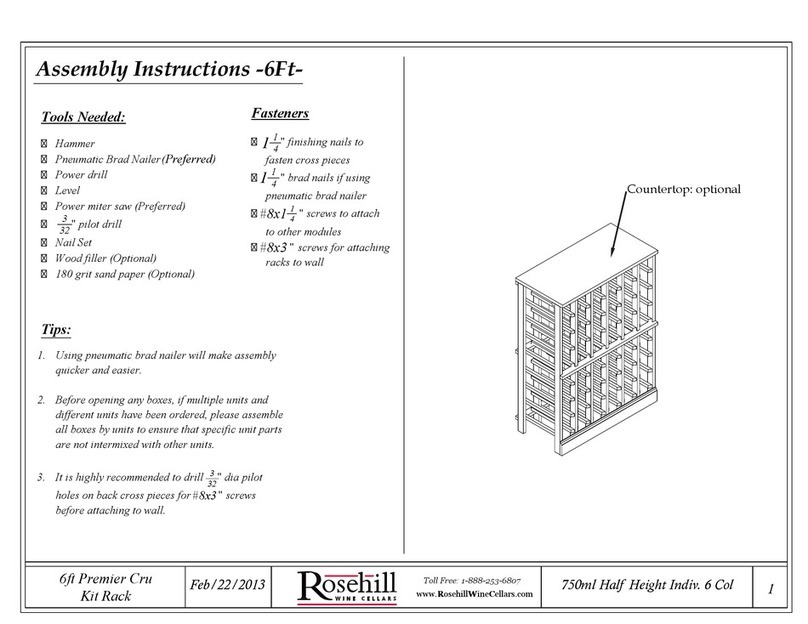
Rosehill Wine Cellars 6ft Premier Cru Kit Rack Assembly instructions
