Srarp UX-385 User manual

UX-385LU
No. 00ZUX385LUSME
CHAPTER 1. GENERAL DESCRIPTION
[1] Specifications ............................................ 1-1
[2] Operation panel......................................... 1-2
[3] Transmittable documents .......................... 1-3
[4] Installation ................................................. 1-4
[5] Quick reference guide ............................... 1-9
[6] Option imaging film specifications............1-10
CHAPTER 2. ADJUSTMENTS
[1] Adjustments............................................... 2-1
[2] Diagnostics and service soft switch .......... 2-2
[3] Troubleshooting ...................................... 2-18
[4] Error code table....................................... 2-19
CHAPTER 3. MECHANISM BLOCKS
[1] General description ................................... 3-1
[2] Disassembly and assembly
procedures ....................................... 3-3
CHAPTER 4. DIAGRAMS
[1] Block diagram ............................................4-1
[2] Wiring diagram .......................................... 4-2
[3] Point-to-point diagram ............................... 4-3
CHAPTER 5. CIRCUIT DESCRIPTION
[1] Circuit description ..................................... 5-1
[2] Circuit description of control PWB ............ 5-2
[3] Circuit description of TEL/LIU PWB .......... 5-8
[4] Circuit description of
power supply PWB............................5-11
[5] Circuit description of CIS unit...................5-11
CHAPTER 6. CIRCUIT SCHEMATICS AND
PARTS LAYOUT
[1] Control PWB circuit ................................... 6-1
[2] TEL/LIU PWB circuit.................................. 6-9
[3] Power supply PWB circuit ...................... 6-14
[4] Operation panel PWB circuit ................... 6-16
CHAPTER 7. OPERATION FLOWCHART
[1] Protocol ..................................................... 7-1
[2] Power on sequence................................... 7-2
CHAPTER 8. OTHERS
[1] Service tools ............................................. 8-1
[2] IC signal name .......................................... 8-4
PARTS GUIDE
CONTENTS
FACSIMILE
MODEL UX-385
Parts marked with " " are important for maintaining the safety of the set. Be sure to replace these parts with specified ones for
maintaining the safety and performance of the set.
This document has been published to be used
for after sales service only.
The contents are subject to change without notice.
SHARP CORPORATION
SERVICE MANUAL
SELECTION CODE DESTINATION
LU L.A.G. (120V)

UX-385LU
(Danish) ADVARSEL !
Lithiumbatteri-Eksplosionsfare ved fejlagtig håndtering.
Udskiftning må kun ske med batteri af samme fabrikat og type.
Levér det brugte batteri tilbage til leverandoren.
(English) Caution !
Danger of explosion if battery is incorrectly replaced.
Replace only with the same or equivalent type
recommended by the equipment manufacturer.
Discard used batteries according to manufacturer’s
instructions.
(Finnish) VAROITUS
Paristo voi räjähtää, jos se on virheellisesti asennettu.
Vaihda paristo ainoastaan laitevalmistajan suosittelemaan
tyyppiin. Hävitä käytetty paristo valmistajan ohjeiden
mukaisesti.
(French) ATTENTION
Il y a danger d’explosion s’ il y a remplacement incorrect
de la batterie. Remplacer uniquement avec une batterie du
même type ou d’un type recommandé par le constructeur.
Mettre au rébut les batteries usagées conformément aux
instructions du fabricant.
(Swedish) VARNING
Explosionsfare vid felaktigt batteribyte.
Använd samma batterityp eller en ekvivalent
typ som rekommenderas av apparattillverkaren.
Kassera använt batteri enligt fabrikantens
instruktion.
(German) Achtung
Explosionsgefahr bei Verwendung inkorrekter Batterien.
Als Ersatzbatterien dürfen nur Batterien vom gleichen Typ oder
vom Hersteller empfohlene Batterien verwendet werden.
Entsorgung der gebrauchten Batterien nur nach den vom
Hersteller angegebenen Anweisungen.
CAUTION FOR BATTERY REPLACEMENT

1 – 1
UX-385LU
CHAPTER 1. GENERAL DESCRIPTION
[1] Specifications
Automatic dialing: Rapid Key Dialing: 5 numbers
Speed Dialing: 40 numbers
Imaging film: Initial starter roll (included with
machine): 32ft. (10 m) roll (approx.30
letter-size pages)
Replacement roll:
UX-3CR 98ft. (30 m) roll (two rolls in
package, one roll yields approx.100
letter-size pages)
Automatic document feeder: 10 sheets max. (20 Ib paper)
Memory size* : 512 KB (approx. 30 average pages with
ECM turned off)
Modem speed: 14,400 bps with automatic fallback to
lower speed
Transmission time* : Approx. 6 seconds (only when ECM is on)
Reception modes: FAX, TEL, TEL/FAX, TAD
Resolution: Horizontal:
203 pels/ineh (8 dots/mm)
Vertical:
Standard: 98 lines/inch (3.85 lines/mm)
Fine/Halftone: 196 lines/inch (7.7 lines/mm)
Super fine: 391 lines/inch (15.4 lines/mm)
Display: 16-digit LCD display
Recording system: Thermal transfer recording
Paper tray capacity: Letter: 60 sheets
(16-to 20-lb. paper) Legal: 30 sheets
Halftone (grayscale): 64 levels
Applicable telephone line: Public switched telephone network
Compatibility: ITU-T (CCITT) G3 mode
Compression scheme: MH, MR, MMR
Scanning method: Sheet-feeder CIS (Contact Image Sensor)
Effective printing width: 8.3" (210mm) max.
Input document size: Automatic feeding:
Width 5.8 to 8.5" (148 to 216 mm)
Length 5.5 to 11" (140 to 279 mm)
Manual feeding:
Width 5.8 to 8.5" (148 to 216 mm)
Length 5.5 to 23.6" (140 to 600 mm)
Effective scanning width: 8.3" (210 mm) max.
Contrast control: Automatic/Dark selectable
Copy function: Single/Multi-copy/Sort-copy
(99 copies/page)
Telephone function: Standard
(cannot be used if power fails)
Power requirements: Standard voltage, 60 Hz
Operating temperature: 41 to 95°F (5 to 35°C)
Humidity: Maximum: 85 %
Power consumption: Stand-by: 4.0 W
Maximum: 100 W
Dimensions: Width: 343 mm
Depth: 256 mm
Height: 182 mm
Weight: Approx. 3.4 kg
* Basedon ITU-T (CCITT)Test Chart #1at standard resolutionin Sharp
special mode, excluding time for protocol signals (i.e., ITU-T phase C
time only).
As a part of our policy of continuous improvement, SHARP reserves the right to make design and specification changes for product
improvement without prior notice.The performance specifications figures indicated are nominal values of production units. There may be some
deviation from these values in individual units.
1 – 2
UX-385LU
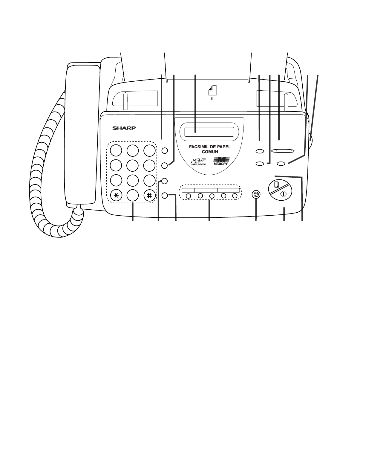
[2] Operation panel
1. Tecla de DISCADO RAPIDO (SPEED DIAL key)
Press this key to dial a 2-digit Speed Dial number.
2. Tecla de REDISCADO (REDIAL key)
Press this key to automatically redial the last number dialed.
3. Pantalla de cristal líquido (Display)
This displays messages and prompts during operation and
programming.
4. MODO DE RECEPCION Tecla
(RECEPTION MODE key)
Press this key to select the reception mode. An arrow in the
display will point to the currently selected reception mode.
5. Tecla de RESOLUCION (RESOLUTION key)
Press this key to adjust the resolution and contrast before
sending or copying a document.
6. Teclas de VOLUMEN (VOLUME keys)
Press these keys to adjust the volume of the speaker when
the SPEAKER key has been pressed, or the volume of the
ringer at all other times.
7. Tecla de FUNCION (FUNCTION key)
Press this key to select various special functions.
8. Cómo abrir el tablero (Panel release)
Grasp this finger hold and pull toward you to open the
operation panel.
9. Teclas numéricas (Number keys)
Use these keys to dial numbers, and enter numbers and
letters during number/name storing procedures.
10. Tecla RETENCION/BUSQUEDA
(HOLD/SEARCH key)
Press this key to search for an automatic dialing number, or,
during a phone conversation, press this key to put the
other party on hold.
11. Tecla de PARLANTE (SPEAKER key)
Press this key to hear the line and fax tones through
the speaker when sending a document.
Note: This is not a speakerphone. You must pick up the
handset to talk with the other party.
12. Teclas rápidas (Rapid Dial keys)
Press one of these keys to dial a fax or voice number
automatically.(Note that you must attach the Rapid Key labels.)
13. Tecla de PARE (STOP key)
Press this key to cancel operations before they are
completed.
14. EMPEZAR/MEMORIA Tecla
(START/MEMORY key)
Press this key to send or receive a document, or to scan a
document into memory before sending it.
15. Tecla de COPIA/AYUDA (COPY/HELP key)
When a document is in the feeder, press this key to make
a copy. At any other time, press this key to print out the
Help List, a quick reference guide to the opeation of your
fax.
11109 12 13 14
81 4 5 62 3
15
7
JKL
DISCADO
RAPIDO
REDISCADO
PARLANTE
RETENCION/
BUSQUEDA
PARE
COPIA/
AYUDA
EMPEZAR
/
MEMORIA
VOLUMEN
BAJO ALTO
MODO DE
RECEPCION
RESOLUCION FUNCION
TEL FAX
TCD
ABC
2
1
DEF
3
WXYZ
9
GHI
45
MNO
6
PQRS
7
TUV
8
0
05/SONDEO
04030201
TEL/FAX
BOCAABAJO
(MAX 10 PAGINAS)
1 – 3
UX-385LU
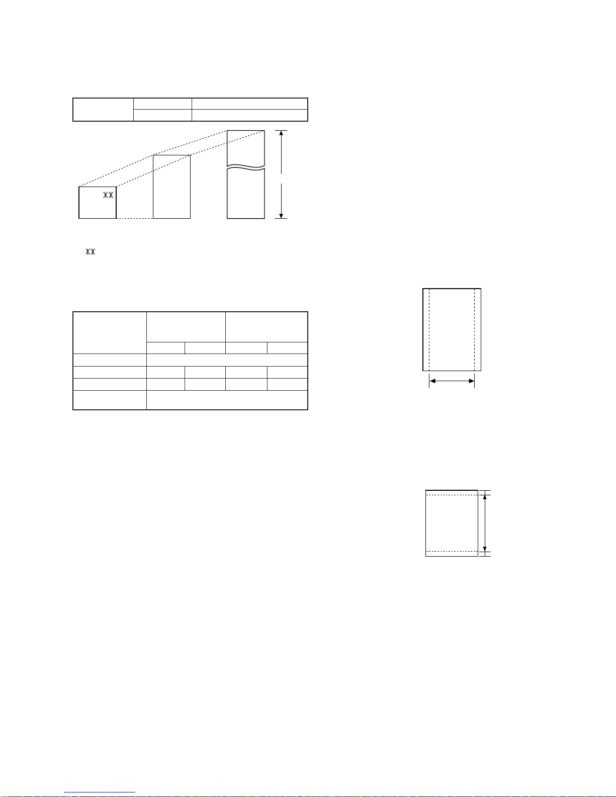
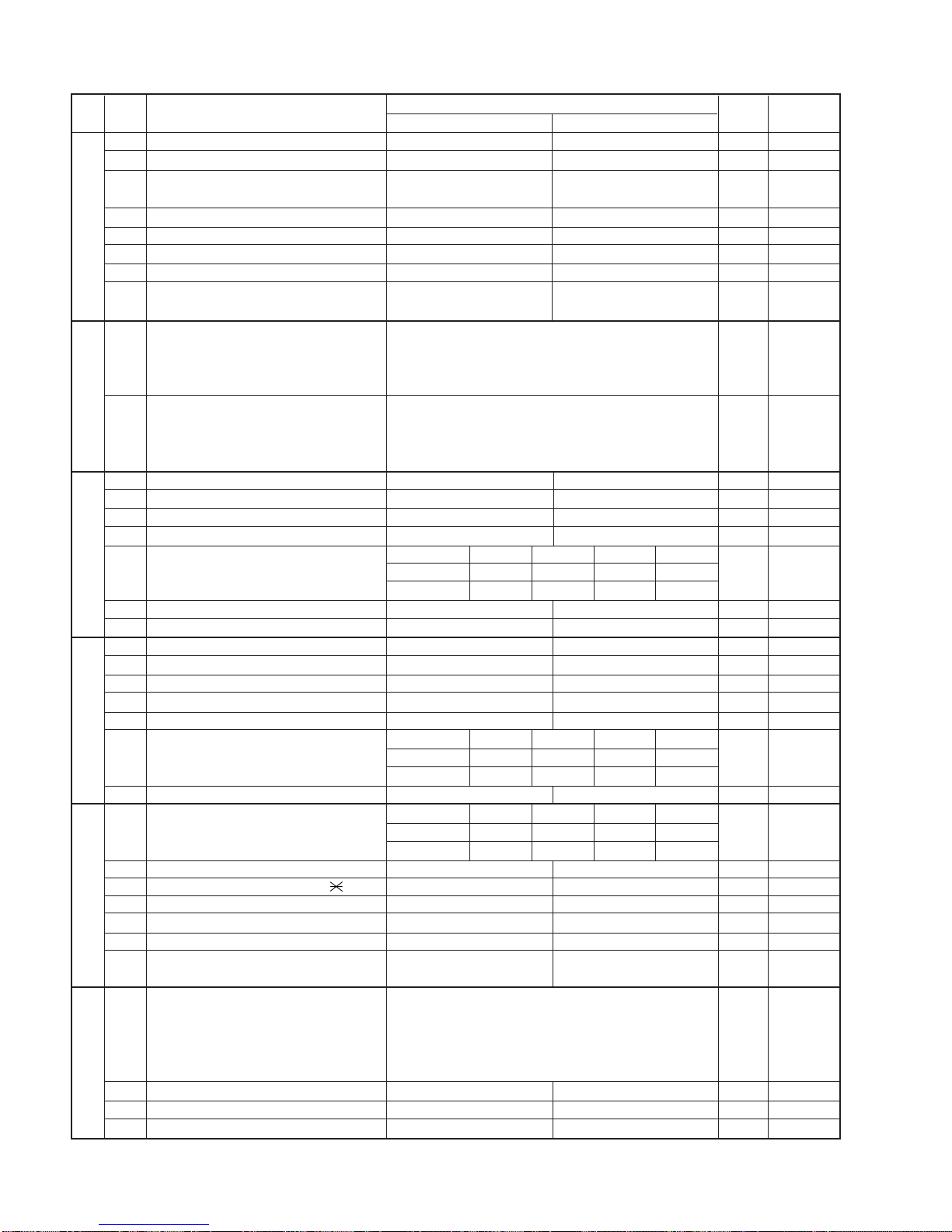
[3] Transmittable documents
1. Document Sizes
* With special sizes, only one sheet can be fed into the machine at a
time. Insert next page into feeder as current page is being scanned.
2. Paper Thickness & Weight
Normal size width 5.8" – 8.5"(148 – 216 mm)
length 5.5" – 11"(140 – 279 mm)
5. Automatic Document Feeder Capacity
Number of pages that can be placed into the feeder at anytime is as
follows:
Normal size: max. ADF 10 sheets
Special size: single sheet only (manual feed)
NOTES: •Whenyouneed to send orcopymorepages than thefeeder
limit, place additional pages in feeder when last page in
feeder is being scanned.
•Place additional pages carefully and gently in feeder.
If force is used, double-feeding or a document jam may
result.
6. Readable Width & Length
The readable width and length of a document are slightly smaller than
the actual document size.
Note that characters or graphics outside the effective document scan-
ning range will not be read.
•Readable width
8.3" (210mm), max.
•Readable length
This is the length of the document sent minus 0.2" (5mm) from the top
and bottom edges.
Use document carrier sheet for smaller documents.
Readable width
(Min.) (Max.)
Letter
size
(Max.)
140mm
279mm 600mm
148mm 216mm
[
Normal size
]
216mm
[
Special size
]
3. Document Types
• Normal paper
Documents handwritten in pencil (No. 2 lead or softer), fountain
pen, ball-point pen, or felt-tipped pen can be transmitted.
Documents of normal contrast duplicated by a copying machine
can also be transmitted.
• Diazo copy (blue print)
Diazo copy documents of a normal contrast may be transmitted.
• Carbon copy
A carbon copy may be transmitted if its contrast is normal.
4. Cautions on Transmitting Documents
• Documentswritteninyellow, greenishyellow,or light blueinkcannot
be transmitted.
• Ink, glue, and correcting fluid on documents must be dry before
the documents can be transmitted.
• All clips, staples and pins must be removed from documents be-
fore transmission.
• Patched (taped) documents should be copied first on a copier and
then the copies used for transmission.
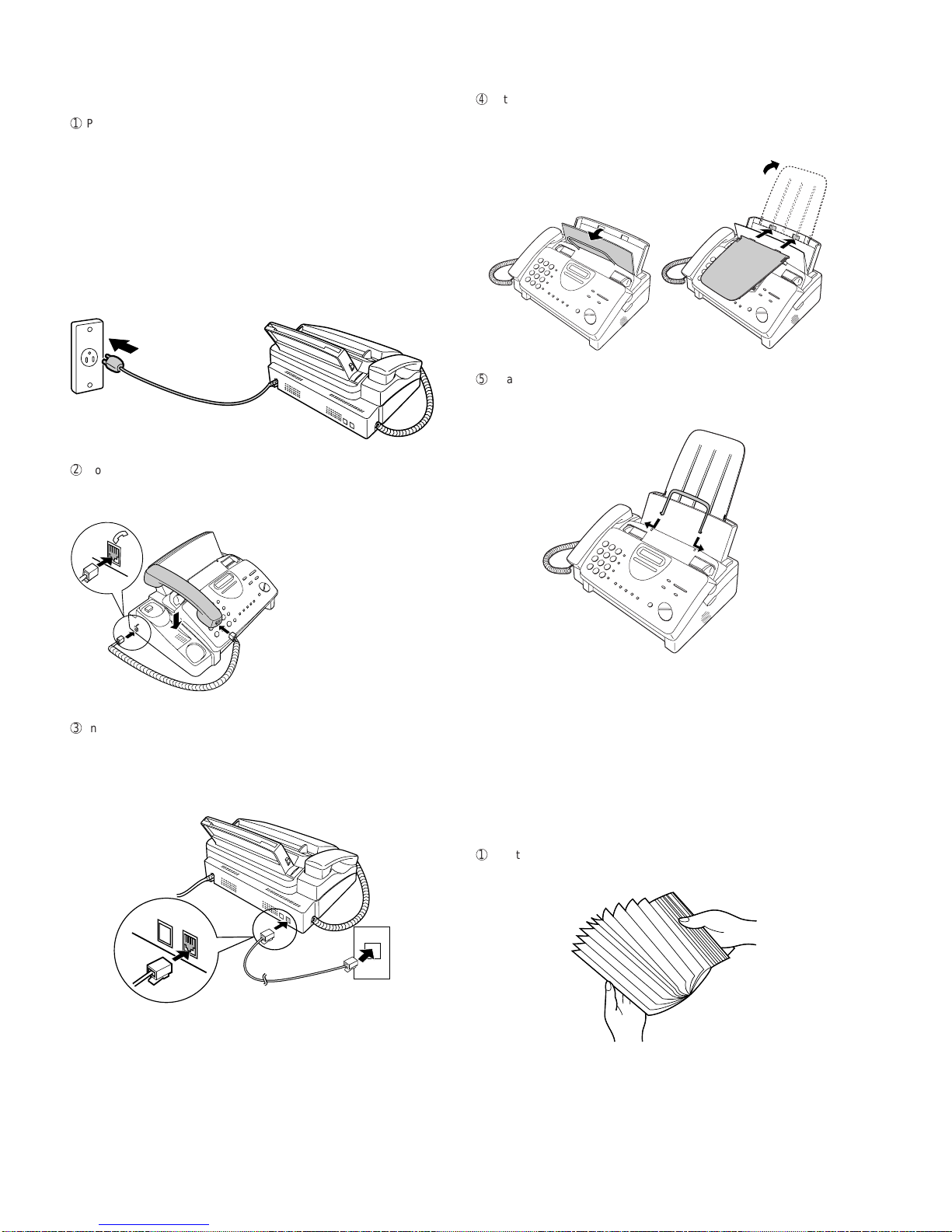
• All documents should be fanned before insertion into the feeder to
prevent possible double feeds.
0.2"(5mm)
0.2"(5mm)
Readable length
Paper size 148mm x 140mm ~
A4 (210mm x 297mm), Letter (216mm x 279mm)
4x6 series
(788mm x 1091mm x
1000 sheets)
Square
meter series
Minimum Maximum Minimum Maximum
Feeder capacity 10 sheets, max.
Paper thickness (ref.)
0.06mm 0.09mm 0.06mm 0.09mm
Paper weight 45kg 64.3kg 52g/m274.3g/m2

1 – 4
UX-385LU
7. Use of Document Carrier Sheet
A document carrier sheet must be used for the following documents.
•Those with tears.
•Those smaller than size 5.8" (W) x 5.5" (L) (148mm (W) x 140mm
(L)).
•Carbon-backed documents
NOTE: To transmit a carbon-backed document, insert a white sheet of
paper between the carbon back of the document and the docu-
ment carrier.
•Those containing an easily separable writing substance (e.g., track-
ing paper written on with a soft, heavy lead pencil).
NOTES: •When using the document carrier, carefully read the in-
structions written on the back.
•If the document carrier is dirty, clean it with a soft, moist
cloth, and then dry it before using for transmission.
•Do not place more than one document in the carrier at a
time.
[4] Installation
1. Site selection
Take the following points into consideration when selecting a site for this
model.
ENVIRONMENT
•The machine must be installed on a level surface.
•Keep the machine away from air conditioners, heaters, direct sun-
light, and dust.
•Provide easy access to the front, back, and sides of the machine. In
particular, keep the area in front of the machine clear, or the original
document may jam as it comes out after scanning.
•The temperature should be between 41 to 95°F (5°to 35°C).
•The humidity should be between 30% and 85% (without conden-
sation).
ELECTRICITY
Standard voltage, 60Hz, grounded AC outlet is required.
Caution!
•Connection to a power source other than that specified will cause
damage to the equipment and is not covered under the warranty.
•Ifyourarea experiences ahighincidence of lightningorpower surges,
we recommend that you install a surge protector for the power and
telephonelines.Surgeprotectors can be purchasedatmosttelephone
speciality stores.
If the machine is moved from a cold to a warm place...
Condensation may form on the reading glass if machine is moved from
a cold to a warm place, this will prevent proper scanning of documents
for transmission.Turn on the power and wait approximately 2 hours be-
fore using machine.
TELEPHONE JACK
A standard telephone jack must be located near the machine.
This is the telephone jack commonly used in most homes and offices.
•Plugging the fax machine into a jack which is not telephone jack may
result in damage to the machine or your telephone system.If you do
not know what kind of jack you have, or need to have one installed,
contact the telephone company.
2. Loading the imaging film (UX-3CR)
Your fax uses a roll of imaging film to create printed text and images.
The print head in the fax applies heat to the imaging film to transfer ink
to the paper. Follow the steps below to load or replace the film.
•The initial starter roll of imaging film included with your fax can print
about 30 letter-size pages.
•When replacing the film, use a roll of Sharp UX-3CR imaging film.
One roll can print about 100 letter-size pages.
Note: If there is paper in the paper tray, pull the paper release plate
forward and remove the paper before loading the imaging film.
1
Open the operation panel by grasping the finger hold and pulling up.
Direction of insertion
Make print straight
across paper
E.G.
Place the document
carrier in the document
feeder with the clear film
side down
If you are installing the imaging film for the first
time, go to Step 6.
2
Pull the green release on the right side of the machine forward, and
open the print compartment cover.
3
Removetheimaging film cartridge fromthe printcompartment(grasp
the handle at the front of the cartridge) and turn it over.

1 – 5
UX-385LU
4
Remove the used film from the cartridge.
5
Remove the four green gears from the used film.
DO NOT DISCARD THE FOUR GREEN GEARS!
6
Remove the new roll of imaging film from its packaging.
• Do not yet remove the band that holds the rolls together.
7
Insert the large gear into the green end of the empty spool. Make
sure the two protrusions on the large gear fit firmly into the slots in
the end of the spool.
Insert the remaining three gears into the spools, making sure the
protrusion on each gear fits firmly into one of the slots in the end of
each spool.
• If needed, pull the spools apart slightly to allow the gears to fit
(the band will stretch).
9
Cutthe band thatholds the two spools together.Unroll thefilm slightly
and insert the small gears into their holders.
F
Turn the cartridge over, grasp the handle, and insert the cartridge
into the print compartment.
Slot
Protrusion
Large gear
8
Insertthe large gearinto the largeholder on theimaging film cartridge
(make sure it clicks into place), and then insert the small gear on the
other end of the spool into its holder.
G
Rotate the large gear toward you until the film is taut.
H
Closethe print compartment cover(press down onbothsides to make
sure it clicks into place), and then close the operation panel.
Click!
I
Load paper in the paper tray and then press the following keys to
initialize the film.
Note:Paper must be loaded before the film can be initialized.To load
paper, see the following section, Loading Printing Paper.
When to replace the imaging film
Replace the imaging film when the display shows:
Use the following imaging film, which is available from your dealer
or retailer: Sharp UX-3CR Imaging Film
FIN DE PELICULA
FUNCION 6
EMPEZAR/MEMORIA
INICIAR FILM
Display shows:
1 – 6
UX-385LU
3. Assembly and connections
1
Plug the power cord into a standard voltage, 60Hz, grounded AC
outlet.
•Caution:Do not plug the power cord into any other kind of outlet.
This will damage the machine and is not covered under the
warranty.
• The machine does not have a power on/off switch, so the power
isturned on andoff bysimplyplugging in or unplugging the power
cord.
Note: If your area experiences a high incidence of lightning or power
surges, we recommend that you install surge protectors for
the power and telephone lines. Surge protectors can be
purchased at most telephone specialty stores.
2
Connect the handset as shown and place it on the handset rest.
♦ The ends of the handset cord are identical, so they will go into
either jack.
3
Insert one end of the telephone line cord into the jack on the back of
the machine marked TEL.LINE.Insert the other end into a standard
(RJ11C) single-line wall telephone jack.
Be sure to insert the telephone line cord into the TEL.LINE jack.
Do not insert into the TEL.SET jack.
Make sure the handset cord
goes into the jack marked
withahandset symbol on the
side of the machine!
Use the handset to make ordinary
phonecalls,orto transmit andreceive
documents manually.
TEL.
LINE
TEL.
SET
4
Attach the paper tray extension.
♦ Pull the paper release plate forward. Insert the paper tray exten-
sion horizontally into the notches in the paper tray. Rotate the pa-
per tray extension up until it snaps into place.
5
Attach the original document support.
Note: The original document support has a top side and a bottom
side.If you cannot insertthe tabson the supportinto the holes,
turn the support over.
4. Loading printing paper
You can load letter or legal size paper in the paper tray. The maximum
number of sheets depends on the weight and size of the paper you are
loading.
♦Paper from 16 to 20 Ibs.(60 to 75 g/cm2):
Letter size:60 sheets Legal size: 30 sheets
♦Paper from 20 to 24 Ibs.(75 to 90 g/cm2):
Letter size:50 sheets Legal size: 25 sheets
Note: If you are going to use letter size paper, remove the A4 paper
guide from the right side of the paper tray.
1
Fan the paper, and then tap the edge against a flat surface to even
the stack.

1 – 7
UX-385LU
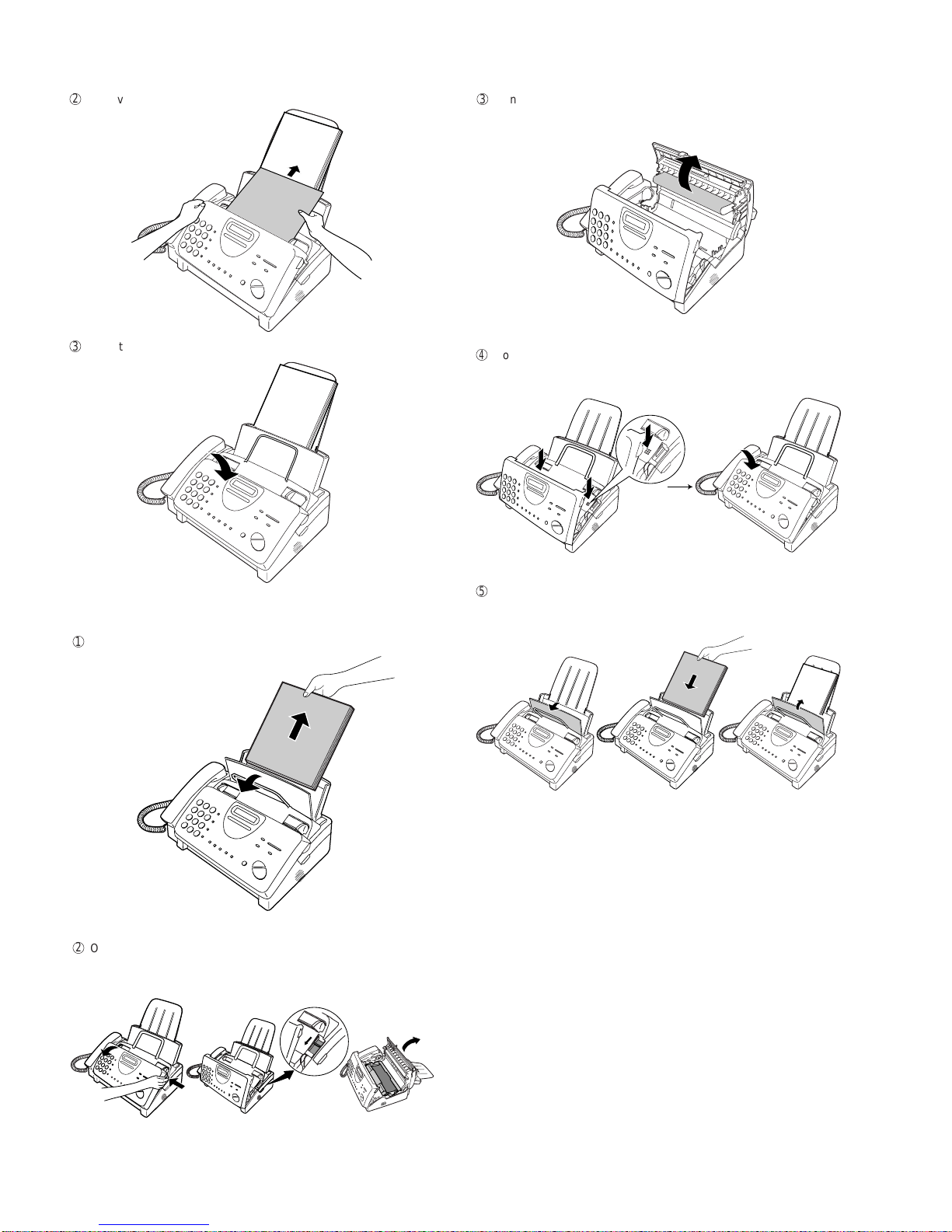
2
Pull the paper release plate toward you.
4
Push the paper release plate back down.
• If the paper release plate is not pushed down, paper feed errors will
result.
Note: When receiving faxes or copying documents, do not allow a
large number of pages to accumulate in the output tray. This may
obstruct the outlet and cause paper jams.
Note: If the display shows the following alternating messages when
making a copy or receiving a fax, check the paper tray. If the tray is
empty, add paper and then press the START/MEMORY key. If there
ispaper,make sure itis insertedcorrectly andthen press theSTART/
MEMORY key.
5
The fax has been set at the factory to scale the size of received faxes
to letter size paper.If you have loaded legal paper, you must change
the paper size setting to legal.Press these keys:
FUNCION
6
The display will show: FIJAR TAMAÑO PAG
Press 1to select LETTER, 2to select LEAGAL,
or 3 select A4.
The display will show: CORTE DE COPIA
Press the STOP key to return to the date and time display.
1
or
2
LETTER LEAGAL
PARE
or
3
A4
3
Insert the stack of paper into the tray, print side down.
• If paper remains in the tray, take it out and combine it into a single
stack with the new paper before adding the new paper.
Be sure to load the paper so that printing takes place on the print
side of the paper.Printing on the reverse side may result in poor print
quality.
6
Your fax has been set at the factory to print at normal contrast.
Depending on the type of paper you have loaded, you may find that
you obtain better print quality by changing the setting to LIGHT.
Press these keys:
5. Clearing a jammed document
If the original document doesn’t feed properly during transmission or
copying, orDOCUMENT JAMMED appears inthedisplay,firsttrypress-
ing the START/MEMORY key. If the document doesn’t feed out, open
the operation panel and remove it.
Important:
Do not try to remove a document without opening the operation panel.
This may damage the feeder mechanism.
1
Open the operation panel by grasping the finger hold and pulling up.
FUNCION
6
The display will show: CONTRASTE IMPRES
Press 1to select NORMAL or 2to select LIGHT.
The display will show: FIJAR TAMAÑO PAG
Press the STOP key to return to the date and time display.
1
or
2
NORMAL LIGHT
PARE
COLOQUE PAPEL &
OPRIMA EMPEZAR
↑
↑
1 – 8
UX-385LU
6. Clearing jammed printing paper
1
Pull the paper release plate forward and remove the paper.
2
Open the operation panel (grasp the finger hold and pull up), and
then pull the release on the right side of the machine forward to open
the print compartment cover.
4
Closethe print compartmentcover(press down onbothsides to make
sure it clicks into place), and then close the operation panel.
3
Gently pull the jammed paper out of the machine, making sure no
torn pieces of paper remain in the print compartment or rollers.
Click!
5
Pull the paper release plate toward you, reinsert the paper in the
paper tray and push the paper release plate back down.
2
Remove the document.
3
Close the operation panel, making sure it clicks into place.
If SET PAPER & PRESS START KEY appears in the display, make sure
the paper is inserted correctly and then press the START/MEMORY
key.

1 – 9
UX-385LU
[5] Quick reference guide
INSTALLATION
1. Connect the handset as shown.
2. Plug the power cord into a grounded, standard voltage outlet.
3. Plug one end of the telephone line into the "TEL. LINE" jack on the rear of the
fax, and the other end into your telephone wall jack.
CONNECTING AN ANSWERING MACHINE AND/OR EXTENSIONTELEPHONE
SETTINGTHE DATE ANDTIME
Note: Imaging film and paper must be loaded to perform the following operation.
Press:
Display shows: FIJAR DIA/FECHA
Press the START key:
Enter two digits for the Month (01 through 12).
Enter two digits for the Day (01 through 31).
Enter four digits for theYear (Ex: 2000).
Enter two digits for the Hour (01 through 12).
Enter two digits for the Minute (00 through 59).
Press the key for A.M.or the # key for P.M.
When finished, press:
STORING AND CLEARING NUMBERS FOR AUTO DIALING
Note: Imaging film and paper must be loaded to perform the following operation.
1. Press:
Display shows: MODO # FAX/TEL
2. Press 1to store a number or 2to clear a number.
3. Enter a 2-digit Speed Dial number (from 01 to 05 for Rapid Key Dialing, or 06 to
45 for Speed Dialing). (If you are clearing a number, go to Step 7.)
4. Enter the full telephone/fax number.
5. Press:
6. Enter the name of the location by pressing number keys (max. of 20 charac-
ters).(Refertotheletter entry tablein
ENTERINGYOUR NAMEANDNUMBER
.)
7. Press:
Placeyourdocument(up to 10pages)
face down in the document feeder.
Normal Dialing
1. Lift the handset or press
2. Dial the fax number.
3. Wait for the reception tone (if a person answers, ask them to press their Start
key).
4. Press:
Rapid Key Dialing
Press the appropriate Rapid Key.Transmission will begin automatically.
Speed Dialing
1. Press:
2. Enter 2-digit Speed Dial number.
3. Press:
RECEIVING DOCUMENTS
Press:
FAX mode: The fax automatically answers on 4 rings and receives the incoming
document.
TEL mode:
TEL/FAX mode: The fax machine automatically answers on 4 rings and receives
faxes.Voice calls (including manually dialed fax transmissions) are signalled by a
special ringing sound.
TAD mode: Select this mode when an answering machine is connected to the fax
and the answering machine is turned on.
TEL.
SET TEL.
LINE
1
3
2
TEL.
SET TEL.
LINE
1. Remove the seal covering the "TEL. SET" jack on the rear of the fax.Connect
an extension telephone or answering machine to the "TEL. SET" jack.
2. If desired, connect an extension phone to the answering machine.
ENTERINGYOUR NAME AND NUMBER
Note: Imaging film and paper must be loaded to perform the following operation.
1. Press:
FUNCION
3
Display shows: FIJAR # PROPIO
2. Press:
3. Enter your fax number (max.of 20 digits) by pressing the number keys.
♦If you make a mistake, press the HOLD/SEARCH key to move the cursor
back to the mistake, then enter the correct number or letter.
4. Press:
5. Enter your name by pressing the appropriate number keys as shown below.
♦To entertwoletters insuccessionthatrequire the samekey, pressthe SPEAKER
key after entering the first letter.
6. When finished, press:
EMPEZAR/MEMORIA
A =
B =
C =
D =
E =
F =
G =
H =
I =
J =
K =
L =
M =
N =
O =
P =
Q =
R =
S =
T =
U =
V =
W =
X =
Y =
Z =
SPACE =
REDISCADO
RETENCION/
BUSQUEDA
PARLANTE
123
456
789
0
GHI JKL MNO
TUV WXYZPQRS
DISCADO
PAPIDO
ABC DEF Deletes high-
lighted letter
Upper/lower
case shift key
Moves cursor
to the left
Moves cursor
to the right
Press either key one or more times to select
and enter a symbol.
EMPEZAR/MEMORIA
PARE
FUNCION
3
FUNCION
3
SENDING DOCUMENTS
PARLANTE
DISCADO
RAPIDO
MODO DE
RECEPCION
FAX
TEL
TCD
DEC 14 10:30
TEL/FAX
FAX
TEL
TCD
DEC 14 10:30
TEL/FAX
FAX
TEL
TCD
DEC 14 10:30
TEL/FAX
FAX
TEL
DEC 14 10:30
TCDTEL/FAX
Fax
tone
RECIBIENDO
EMPEZAR/MEMORIA
EMPEZAR/MEMORIA
EMPEZAR/MEMORIA
EMPEZAR/MEMORIA
PARE
EMPEZAR/MEMORIA
EMPEZAR/MEMORIA
PARE
EMPEZAR/MEMORIA
EMPEZAR/MEMORIA
1 – 10
UX-385LU
[6] Option imaging film specifications
(UX-3CR)
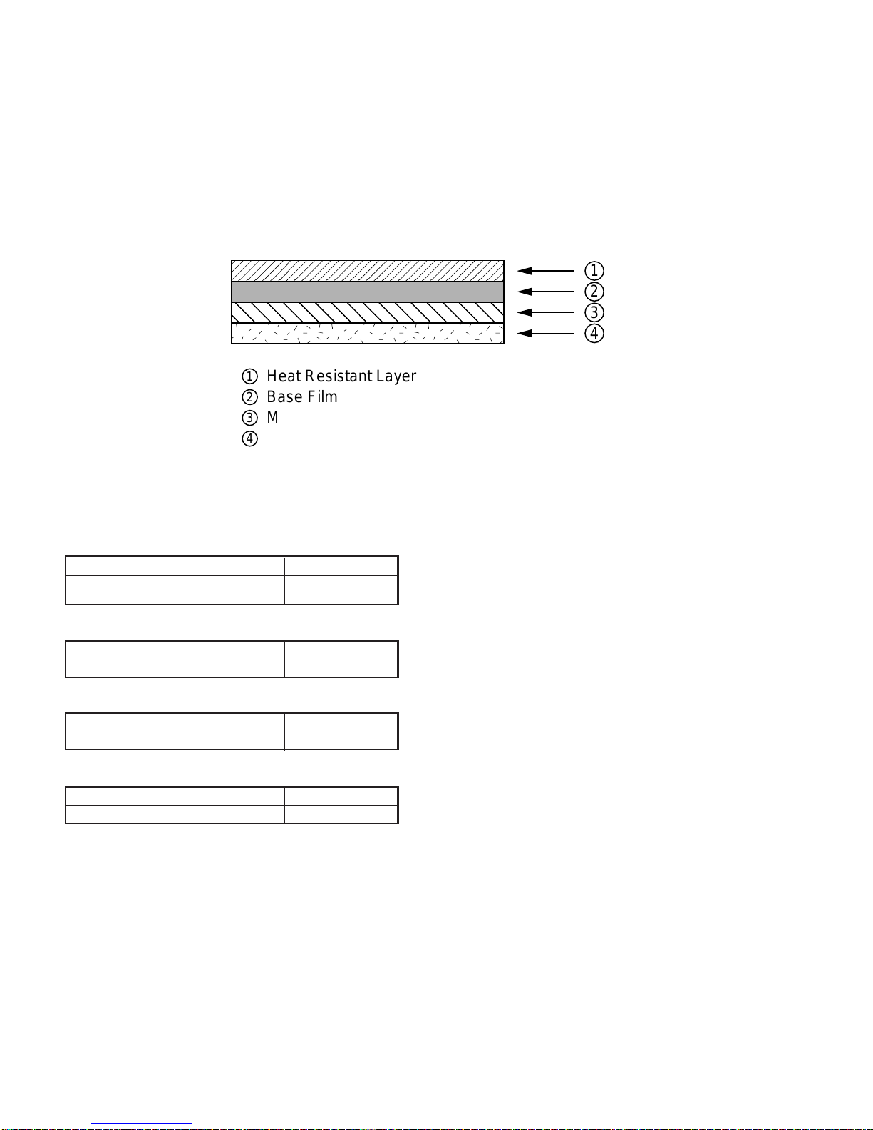
1. Structure
Thisarticleis composedof polyesterfilm coated withheat-resistantlayer,
matt layer and hot melt ink layer, leader film and paper core. Ink film
specification is "DNP standard ink film HC".
Heading Requirements Measuring method
Material Polyethylene-
terephthalate –
Heading Requirements Measuring method
Grade HR Mixer P-5 –
Heading Requirements Measuring method
Grade ML Sumi –
Heading Requirements Measuring method
Grade #507W –
2. Details of compositions
2-1. Base film
2-2. Heat resistant layer
2-3. Matt layer
2-4. Hot melt ink layer
,,,,
,,,,
1
2
3
4
1
2
3
4
Heat Resistant Layer
Base Film
Matt Layer
Hot melt Ink Layer

UX-385LU
CHAPTER 2. ADJUSTMENTS
[1] Adjustments
General
Sincethe followingadjustments andsettings are providedforthismodel,
make adjustments and/or setup as necessary.
1. Adjustments
Adjustments of output voltage (FACTORY ONLY)
1. Install the power supply unit in the machine.
2. Set the recording paper and document.
3. When the document is loaded, power is supplied to the output lines.
Confirm that outputs are within the limits below.
Output voltage settings
3. Settings
(1) Dial mode selector
DIAL mode (Soft Switch No. SWB4 DATA No.3)
Output Voltage limits
+5V 4.75V ∼ 5.25V
+24V 23.3V ∼ 24.7V
2. IC protectors replacement
ICPs (IC Protectors) are installed to protect the motor driver circuit.
ICPsprotect variousICs and electroniccircuits from anovercurrent con-
dition.
The location of ICPs are shown below:
1MG
2MG
3 +24V
4 +24V
5 +24V
6DG
7 +5V
8DG
Connector
No. CNPW
Pin No.
2 – 1
CONTROL PWB
(BOTTOM SIDE)
CNPW CNLIUA
FU100
TEL/LIU PWB
POWER
SUPPLY
PWB
CONTROL
PWB
CNLIUA
CNLIUA CN1
CNPW
CNTH
CNPN
CNCIS
CNSP
CNMT
CNCSW
(step 1) Select "FIJAR OPCIONES".
KEY : FUNCION 4
DISPLAY: FIJAR OPCIONES OPRIMA O #
(step 2) Select "MODO DISCADO".
KEY: Push # until " MODO DISCADO " is
indicated because the number of
# s changes by the model.
DISPLAY: MODO DISCADO
(step 3) Select, using "1" or "2".
KEY: 1
DISPLAY: TONO SELECC.
KEY: 2
DISPLAY: PULSO SELECC.
(step 4) End, using the "PARE" key.
KEY:
Cursor
When initially registering,
the mode shows 1=TONE.
When registering again, the
mode which was registered
formerly is shown.
PARE
1=TONO, 2=PULSO
(1)FU100 (KAB2402) is installed in order to protect IC’s from an over-
current generated in the motor drive circuit.If FU100 is open, replace
it with a new one.
4.Volume adjustment
You can adjust the volume of the speaker and ringer using the ALTO
and BAJO keys.
(1) Speaker
1
Press the PARLANTE key.
2
Press the ALTO or BAJO key.
Display:
VOLUMEN: ALTO
VOLUMEN: MEDIO
VOLUMEN: BAJO
3
When the display shows the desired volume level, press the
PARLANTE key to turn off the speaker.
(2) Ringer
1
Press the ALTO or BAJO key. (Make sure the PARLANTE key has
not been pressed and the handset is not lifted.)
Display:
TIMBRE: ALTO
TIMBRE: MEDIO
TIMBRE: BAJO
SIN TIMBRE: OK?
2
If you selected RINGER OFF: OK?, press the EMPEZAR/MEMORIA
key.
↔
↔
↔
↔
↔
The ringer will ring once
atthe selectedlevel, then
the date and time will re-
appear in the display.
UX-385LU
[2] Diagnostics and service soft switch
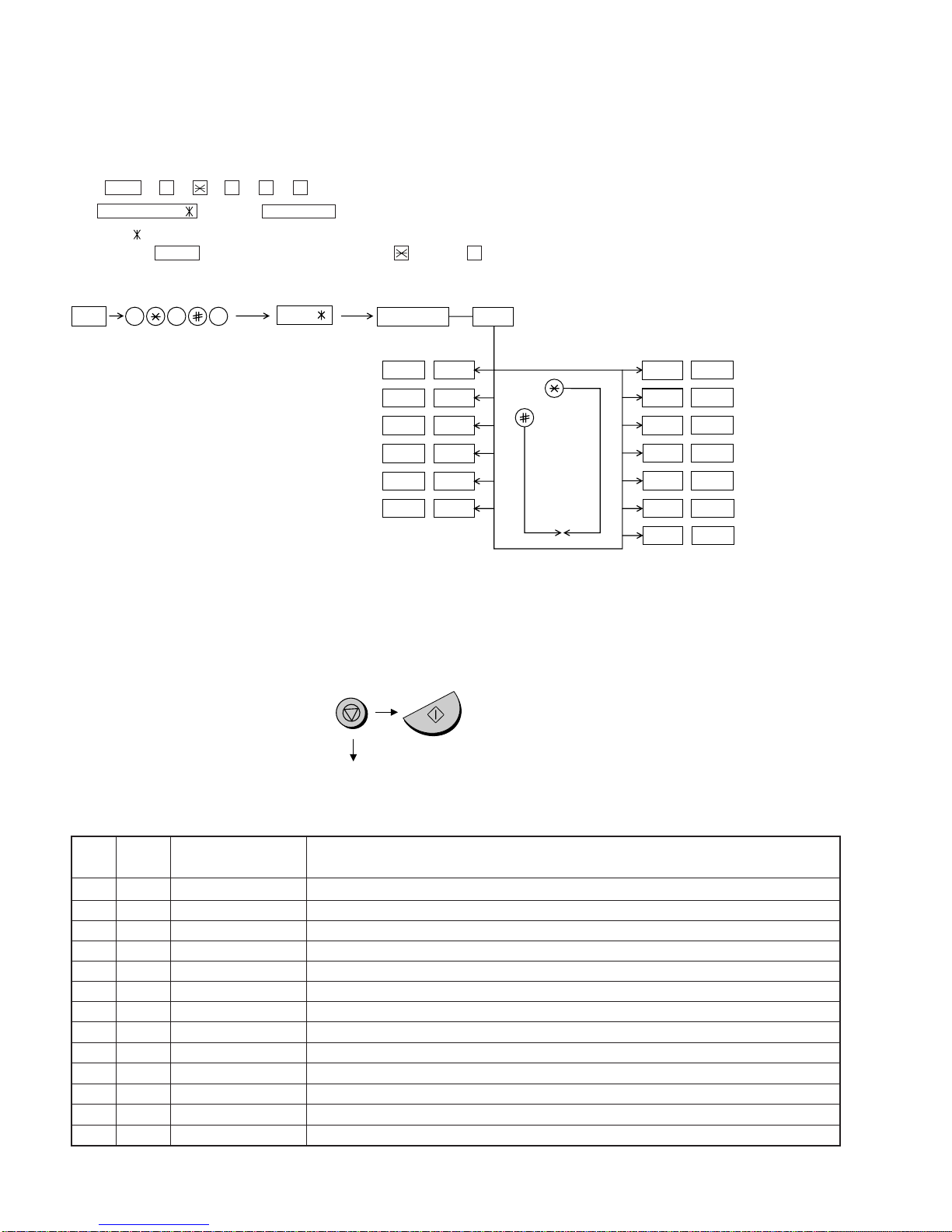
1. Operating procedure
(1) Entering the diagnostic mode
Press FUNC →9 →→ 8 →# →7 , and the following display will appear.
ROMVer. FQB0 After 2 sec: DIAG MODE
FQB0
Then press the START key. Select the desired item with the key or the # key or select with the rapid key. Enter the mode with the START key.
(Diag•specifications)
2. Diagnostic items
ITEM DIRECT Contents Function
No. key
1 1 SOFT SWITCH MODE Soft switches are displayed and changed. List can be output.
2 2 ROM & RAM CHECK ROM is sum-checked, and RAM is matched. Result list is output.
3 3 AGING MODE 10 sheets of check patterns are output every 5 minutes per sheet.
4 4 PANEL KEY TEST Panel keys are tested. Result list is output.
5 5 CHECK PATTERN Check pattern is output.
6 — SIGNAL SEND MODE Various signals of FAX communication are output.
7 — MEMORY CLEAR Back-up memory is cleared, and is set at delivery.
8 — SHADING MODE Shading compensation is performed in this mode.
9 — ALL BLACK PRINT To check the print head, whole dots are printed over the interval of 2 m.
10 — AUTO FEEDER MODE Insertion and discharge of document are tested.
11 — ENTRY DATA SEND Registered content is sent.
12 — ENTRY DATA RECEIVE Registered content is received, and its list is output.
13 — MESSAGE PRINT The display message of each language is printed out together with the English equivalent.
If the diag mode cannot be set, repeat the diag mode operation, per-
forming the following operation.
After the power is turned on and "WAIT A MOMENT" is indicated, press
the STOP key.
2 – 2
In relation with the process response (request from Production
Engineering)"WAITA MOMENT" clockindication mayappear depending
onSTOP keytiming.If the STOP key isheld down,"MEMORYCLEAR?"
appears.
FUNC DIAG MODE
9 8 7
START 1Soft switch mode
START 2ROM & RAM check
START 3Aging mode
START 4Panel key test
START 5Check pattern
START —Signal send mode
START
START
KEY
STOP
KEY
+
"Power ON"
Memory clear
(Work + Backup)
Shading mode
START
START
All black print
START
—Auto feeder mode
START
—
Entry data send
Entry data receive
START
Memory clear
START
—
—
—
—
FQB0
START Message print
—
UX-385LU
3. Diagnostic items description
3. 1. Soft switch mode
Used to change the soft switch settings.
The soft switch which is stored internally is set by using the keys.
The available soft switches are SW-A1 to SW-N3.
The content of soft switches is shown in page 2-5 to 2-17.
The contents are set to factory default settings.
3. 2. ROM & RAM check
ROM executes the sum check, and RAM executes the matching test.
The result will be notified with the number of short sounds of the buzzer
as well as by printing the ROM & RAM check list.
Number of short sounds of buzzer 0 →No error
1 → ROM error
2 → RAM error (32Kbyte)
3. 3. Aging mode
If any documentis first present, copying will be executed sheetby sheet.
If no document is present, the check pattern will be printed sheet by
sheet.This operation will be executed at a rate of one sheet per 5min-
utes, and will be ended at a total of 10 sheets.
3. 4. Panel key test
This mode is used to check whether each key operates properly or not.
Press the key on the operation panel, and the key will be displayed on
the display.Therefore, press all keys.At this time, finally press the STOP
key.
When the STOP key is pressed, the keys which are not judged as
"pressed" will be printed on the result list.
• LED part of the contact image sensor (CIS) is kept on during the term
from when "START" of the panel test mode to end with the STOP key.
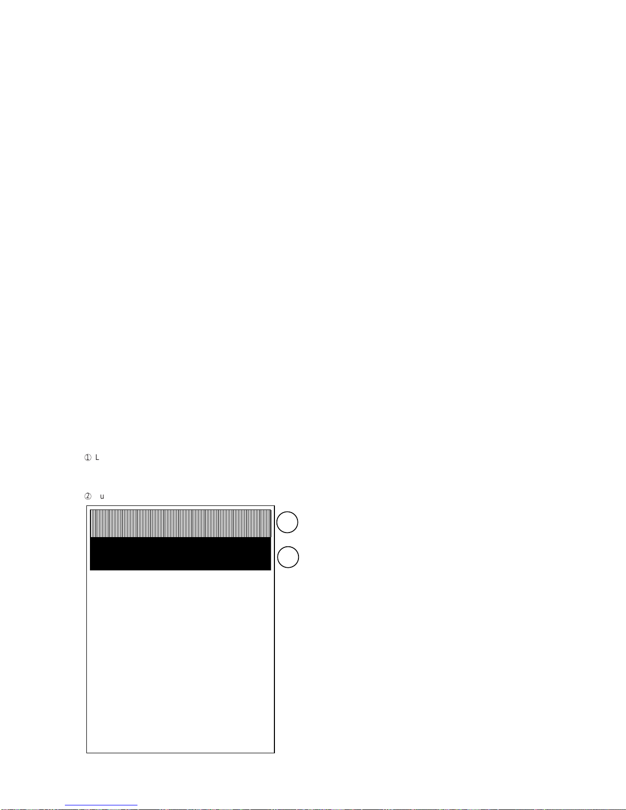
3. 5. Check pattern
This mode is used to check the state of the printing head. It is ended
with the following pattern printed on one printing sheet.
1
Longitudinal stripe 2 Approx. 30 mm
2 black dots and 2 white dots are repeatedly progressed on one
line.
2
Full black Approx. 30 mm
3. 6. Signal send mode
This mode is used to send various signals to the circuit during FAX com-
munication. Every push of START key sends a signal in the following
sequence.Moreover,the signalsoundis alsooutputto thespeaker when
the line monitor of the soft switch is on.
[1] No signals
[2] 14400BPS (V.33)
[3] 12000BPS (V.33)
[4] 14400BPS (V.17)
[5] 12000BPS (V.17)
[6] 9600BPS (V.17)
[7] 7200BPS (V.17)
[8] 9600BPS (V.29)
[9] 7200BPS (V.29)
[10] 4800BPS (V27ter)
[11] 2400BPS (V27ter)
[12] 300BPS (FLAG)
[13] 2100Hz (CED)
[14] 1100Hz (CNG)
[15] PSEUDO RINGER
3. 7. Memory clear
This mode is used to clear the backup memory and reset to the default
settings.
3. 8. Shading mode
The mode is used for the shooting compensation. For reading, set up
the special original paper.
The shooting compensation memorizes the reference data of white and
black for reading.
Moreover, the memorized data is not erased even if memory clear mode
is executed.
3. 9. All black print
This mode is used to check the state of the printing head and inten-
tionally overheat it. Whole dots are printed over the interval of 2 m. If it is
overheated or the printing sheet is jammed, press STOP key for the end.
3. 10. Auto feeder mode
In this mode, a document is inserted and discharged to check the auto
feed function.
After this mode is started, set a document, and the document feed will
be automatically tested.
3. 11. Entry data send
This mode is used to send the registered data to the other machine and
make the other machine copy the registered content.
Before sending in this mode, it is necessary to set the other machine at
the entry data receive mode.
The following, information will be sent to the remote machine:
1. Telephone list data
2. Sender register data
3. Optional setting content
4. Soft switch content
5. Junk fax number list
6. Timer reservation data (only on the model which timer reserva-
tion is possible)
7. Recording setting list data
2 – 3
1
2

UX-385LU
3. 12. Entry data receive
In this mode, the registered data sent from the other machine is receiv-
ed and the received data is registered in the machine. When this mode
is used for receiving, the other machine must be in the entry data send
mode.
After receiving is completed, the following lists are printed.
1. Telephone list data
2. Senderregister data (The passcodeNo.isalsoprinted if thepolling
function is provided.)
3. Optional setting list
4. Soft switch content
5. Junk fax number list
6. Timer reservation list (only model which timer communication is
possible)
7. Recording setting list data
2 – 4
Press FUNCTION 9 8 7 STARTSTART
Press FUNCTION key.
Press key.
Press key.
Bit1 - 8 are set.
Soft SW-A2 - SW-N3 are set.
S F T SW-A1 = 1 0 0 0 0 0 0 0
S F T SW-A1 = 1 0 0 0 0 0 0 0
S F T SW-A1 = 1 0 0 0 0 0 0 0
S F T SW-A1 = 1 0 0 0 0 0 0 0
S F T SW-A2 = 0 0 0 0 0 0 0 0
S F T SW-N3 = 0 0 0 0 0 0 0 0
Press key during setting.
To finish the settings halfway between
SW-A1 and SW-N3, press the STOP
key. In this case, the setting being done
to the SW No. on display will be nullified
while settings done to the preceding
SW No. remain in effect.
The soft switch mode is terminated.
S F T SW-A1 = 0 0 0 0 0 0 0 0
START
DATA No. 1 2 3 4 5 6 7 8
When the COPY key is pressed, the
contents of soft switches are printed.
3. 13. Message print
In this mode, all the message data, which are used for diaplaying indica-
tion and list print, are printed as a contrast table of the selected lan-
guage and English.
4. How to make soft switch setting
To enter the soft switch mode, press the following key entries in se-
quence.
UX-385LU
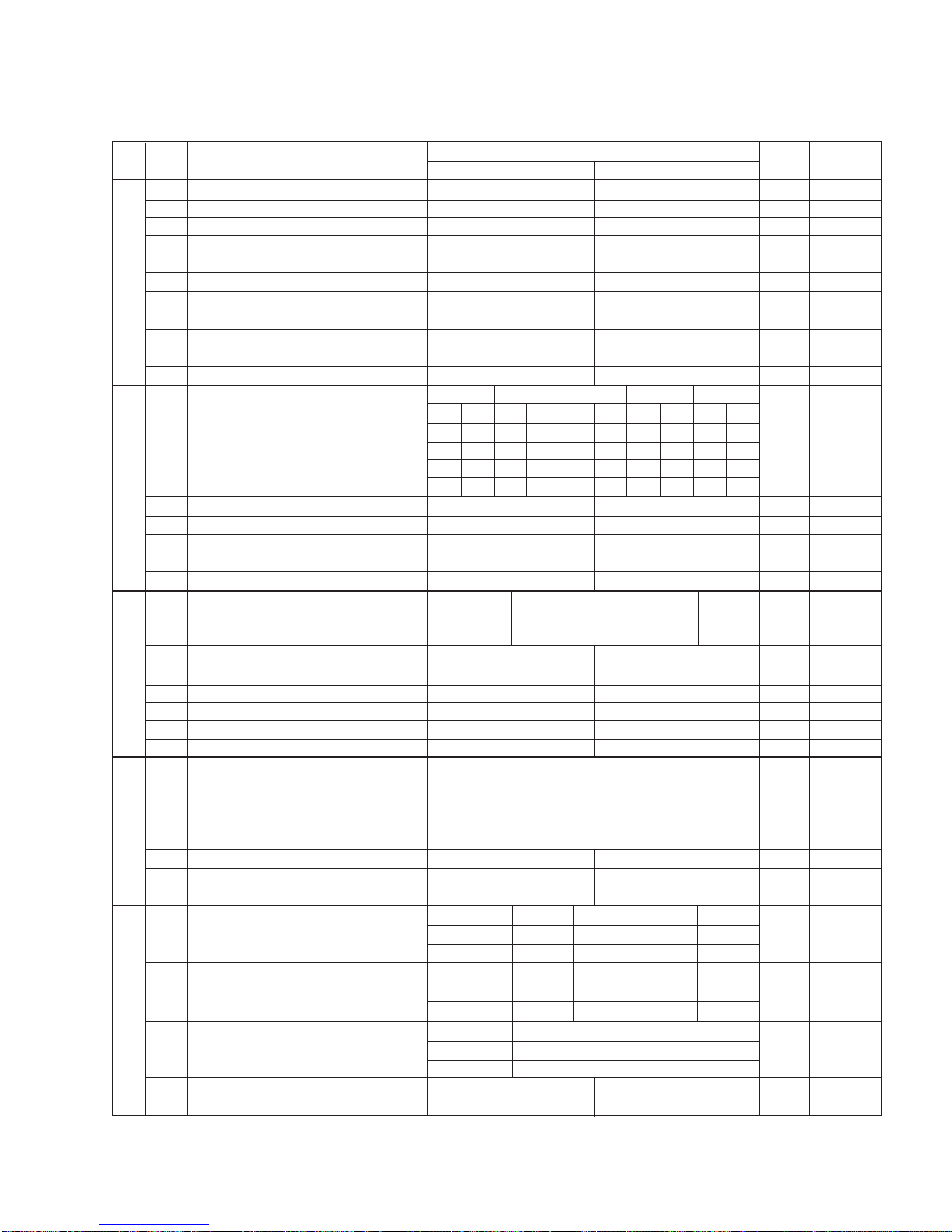
1 Protect from echo No Yes 0
2 Forced 4800 BPS reception Yes No 0
3 Footer print Yes No 0
4 Length limitation of copy/send/receive No limit Copy/send:60cm 0
Receive: 1m
5 CSI transmission No transmitted Transmitted 0
6 DIS receive acknowledgement during G3 Twice NSF: Once 0
transmission DIS: Twice
7 Non-modulated carrier for V29 transmission Yes No 0
mode
8 EOL detect timer 25 s 13 s 0
Modem speed V.33 V.17 V.29 V.27 ter
14400 12000 14400 12000 9600 7200 9600 7200 4800 2400
1 0011110000 1
2 1100000000 0
3 0101010110 0
4 0000111100 0
5 Sender’s information transmit No Yes 0
6 Reserved 0
7 Communication error treatment in RTN No communication error Communication error 0
sending mode (reception)
8 CNG transmission No Yes 0
CED tone signal interval 1000ms 750ms 500ms 75ms
1 No. 1 1 1 0 0 0
2 No. 2 1 0 1 0 0
3 MR coding No Yes 0
4 ECM mode No Yes 0 OPTION
5 ECM MMR mode No Yes 0
6 Reserved 0
7 Reserved 0
8 Reserved 0
1 Signal transmission level Binary input 0
2 No. = 16 8 4 2 1 1
3 1 2 3 4 5 0
4 0 1 0 1 0 1
5 0
6 Protocol monitor (error print) Printed at com. error Not printed 0
7 Protocol monitor Yes No 0
8 Line monitor Yes No 0
Digital line equalization setting (Reception) 7.2km 3.6km 1.8km 0km
1 No.111000
2 No.210101
Digital line equalization setting 7.2km 3.6km 1.8km 0km
3 (Transmission) No. 3 1 1 0 0 0
4 No.410101
Digital cable equalizer setting (Reception 7.2km 0km
5 for Caller ID) No. 5 1 0 0
6No.6100
7 Error criterion 10 ~ 20 % 5 ~ 10 % 0
8 Anti junk fax check Yes No 0 OPTION
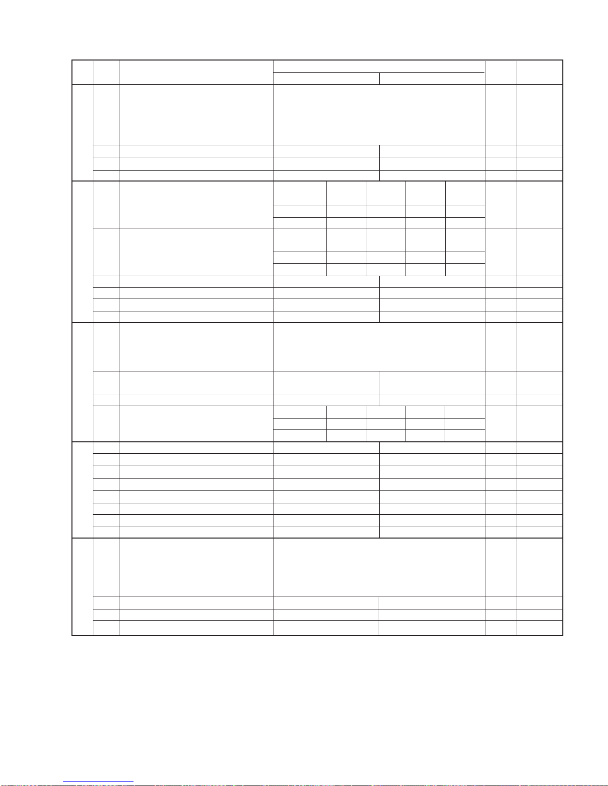
5. Soft switch description
• Soft switch
SW
NO. DATA
NO. ITEM Switch setting and function
10
Remarks
Initial
setting
SW
l
A1
SW
l
A2
SW
l
A3
SW
l
A5
SW
l
A4
2 – 5
UX-385LU
1 Auto gain control (MODEM) Enable Disable 1
2 End Buzzer Yes No 1
3 Disconnect the line when DIS is received in No Yes 1
RX mode
4 Equalizer freeze control (MODEM) On Off 0
5 Equalizer freeze control 7200 BPS only No Yes 0
6 CNG transmission in manual TX mode Yes No 1
7 Reserved 0
8 Modem speed automatic fallback when RX Yes No 0
level is under -40dBm
1 Recall interval Binary input 0 OPTION
2 No. = 8 4 2 1 1
3 1 2 3 4 0
4 0 1 0 1 1
5 Recall times Binary input 0 OPTION
6 No. = 8 4 2 1 0
7 5 6 7 8 1
8 0 0 1 0 0
1 Dial pausing (sec/pause) 4 sec 2 sec 0
2 Dial tone detection (before auto dial) No Yes 1
3 Reserved 0
4 Busy tone detection (after auto dial) No Yes 1
Waiting time after dialing
45 seconds 55 seconds 90 seconds 140 seconds
5No.500110
6No.601010
7 Reserved 0
8 Reserved 0
1 Reserved 0
2 Reserved 0
3 Reserved 0
4 Reserved 0
5 Reserved 0
Auto dial mode delay timer of before line
0 second 1.5 seconds 3.0 seconds 4.5 seconds
6 connect No.6 0 0 1 1 0
7No.701010
8 Hold key Enable Disable 1
Auto dial mode delay timer of after line
1.7 seconds 3.0 seconds 3.6 seconds 4.0 seconds
1 connect No.1 0 0 1 1 0
2No.201010
3 Dial mode Tone Pulse 1 OPTION
4 Pulse →Tone change function by key Enable Disable 1
5 Dial pulse make/break ratio (%) 40/60 33/67 1
6 Reserved 0
7 Reserved 0
8
Recalling fixed only one time when dialing was
Yes No 0
unsuccessful without detecting busy tone signal
1 DTMF signal transmission level (Low) Binary input 0
2 No. = 16 8 4 2 1 1
3 1 2 3 4 5 0
4 0 1 0 1 1 1
5 1
6 Reserved 0
7 Reserved 0
8 Reserved 0
SW
NO. DATA
NO. ITEM Switch setting and function
10Remarks
Initial
setting
SW
l
B5
SW
l
B4
SW
l
B3
SW
l
B2
SW
l
B1
SW
l
A6
2 – 6
UX-385LU
1 DTMF signal transmission level (High) Binary input 0
2 No. = 16 8 4 2 1 0
3 1 2 3 4 5 1
4 0 0 1 1 1 1
5 1
6 Reserved 0
7 Reserved 0
8 Reserved 0
Reading slice (Binary) Factory Light Dark Darker in
setting dark
1No.101010
2 No. 2 0 0 1 1 0
Reading slice (Half tone) Factory Light Dark Darker in
setting dark
3No.301010
4No.400110
5 Line density selection Fine Standard 0 OPTION
6 Reserved 0
7 MTF correction in half tone mode No Yes 0
8 Reserved 0
1 Number of rings for auto receive Binary input 0 OPTION
2 No. = 8 4 2 1 1
3 1 2 3 4 0
4 0 1 0 0 0
5 Automatic switching manual to auto receive Reception after 5 rings No reception 0
mode
6 Reserved 0
Cl detect frequency
As PTT 11.5Hz 13.0Hz 20.0Hz
7 No.700110
8 No.801010
1 Reserved 0
2 Reserved 0
3 Reserved 0
4 Reserved 0
5 Caller ID function Yes No 0 OPTION
6 Caller ID detect during CI off All times Only first 0
7 Reserved 0
8 Reserved 0
1 Cl off detection timer (0-1550ms setting by Binary input 0
2 50ms step) No. = 16 8 4 2 1 1
3 1 2 3 4 5 1
4 0 1 1 1 0 1
5 0
6 Reserved 0
7 Reserved 0
8 Reserved 0
2 – 7
SW
NO. DATA
NO. ITEM Switch setting and function
10Remarks
Initial
setting
SW
l
B6
SW
l
C1
SW
l
D2
SW
l
D1
SW
l
D3

UX-385LU
1 Tel/Fax Automatic switching mode Tel/Fax auto switch Switch to Fax 1
Pseudo ringing time at phone/fax automatic 15sec 60sec 30sec 120sec OPTION
2 switching mode No.2 0 0 1 1 0
3No.301010
4 Number of CNG signal detection at the Twice Once 1
tel/fax automatic switching mode
5 CNG detection when TEL/FAX mode 3sec 5sec 0
6 Reserved 0
7 Reserved 1
8 Reserved 1
1 Pseudo ringer sound volume Binary input 1
2 No. = 8 4 2 1 0
3 1 2 3 4 1
4 1 0 1 0 0
5 Reserved 1
6 Reserved 0
7 Reserved 1
8 Reserved 0
1 Reserved 0
2 Reserved 0
3 Reserved 0
4 Reserved 0
5 Reserved 0
6 Reserved 0
7 Reserved 0
8 Reserved 0
DTMF detection time 50ms 80ms 100ms 120ms
1No.100110
2No.201010
3 Protection of remote reception (5 ) detect Yes No 0 OPTION
4 Remote reception with GE telephone Compatible Not compatible 1
5 Remote operation code figure by external Binary input 0 OPTION
6 TEL (0~9) No. = 8 4 2 1 1
7 5 6 7 8 0
8 0 1 0 1 1
1 CNG detection in STAND-BY mode Yes No 1 OPTION
Number of CNG detect (AM mode) 1pulse 2pulses 3pulses 4pulses
2No.200110
3 No. 3 0 1 0 1 1
Number of CNG detect (STAND-BY mode) 1pulse 2pulses 3pulses 4pulses
4No.400110
5 No. 5 0 1 0 1 1
6 Reserved 0
7 Reserved 0
8 Reserved 0
1 Quiet detect time Binary input 0 OPTION
2 No. = 8 4 2 1 1
3 1 2 3 4 0
4 0 1 0 0 0
5 Quiet detect start timing Binary input 0
6 No. = 8 4 2 1 1
7 5 6 7 8 0
8 0 1 0 1 1
SW
l
E1
SW
NO. DATA
NO. ITEM Switch setting and function
10Remarks
Initial
setting
2 – 8
SW
l
E2
SW
l
E3
SW
l
F1
SW
l
F2
SW
l
G1
Table of contents


