I- 2
2. SPECIFICATIONS
The tables below list the detailed specifications of typical models. The specifications of other
models differ from them on the points of with/without handset, LCD type and others according to
destinations as shown on page I-7. (1/2)
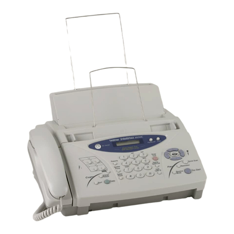
Model Name FAX560 FAX580MC MFC660MC
Engine Thermal transfer Thermal transfer Thermal transfer
Color Upper: New Personal white
(1485)
Lower: 1473 gray
Upper: New Personal white
(1485)
Lower: 1473 gray
Upper: MFC white
(1495 gray)
Lower: 1473 gray
Transmission Speed (sec) 15 9 9
Modem Speed (bps) 9600 14,400 14,400
Group Compatibility G3 G3 G3
Input/Output Width 8.5"/8.5" 8.5"/8.5" 8.5"/8.5"
ADF (pages) 10 10 10
Paper Feeder (sheets) Letter: 50*, Legal: 30 Letter: 50*, Legal: 30 Letter: 50*, Legal: 30
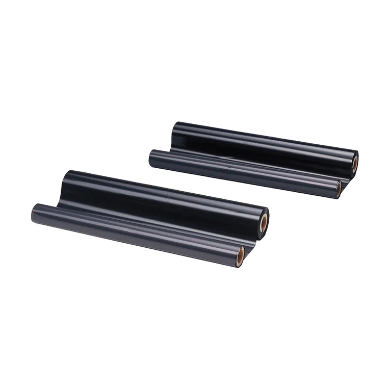
Ribbon Yield (letter-size) 150 pages (47 m) 150 pages (47 m) 150 pages (47 m)
Starter Ribbon Yield (letter-size) 30 pages (10 m) 30 pages (10 m) 30 pages (10 m)
Replacement Roll PC401: 47 m (150 pages) PC401: 47 m (150 pages) PC401: 47m (150 pages)
LCD Size 16 x 1 16 x 1 16 x 1
On-Screen Programming Yes Yes Yes
Super Fine Yes Yes Yes
Smoothing Yes Yes Yes
Gray Scale (levels) 64 by Dithered 64 by Dithered 64 by Dithered
One Touch 4 4 4
Speed Dial 50 50 50
Telephone Index Yes as "Search" Yes as "Search" Yes as "Search"
Speaker Phone Monitor Full duplex (digital) Full duplex (digital)
Handset Yes Yes Yes
FAX/TEL Switch Yes Yes Yes
Distinctive Ring Detection Yes Yes Yes
Caller ID Yes Yes Yes
Call Waiting Caller ID Yes Yes Yes
TAD Interface Yes Yes Yes
Enhanced Remote Activation Yes Yes Yes
Automatic Redial Yes Yes Yes
Next-FAX Reservation Yes Yes Yes
Multi-Resolution Transmission Yes Yes Yes
Polling Type Sim/Seq Sim/Seq Sim/Seq
Delayed Transmission 3-timer 3-timer 3-timer
Call Reservation Yes Yes Yes
Electronic Coverpage Yes-Super Yes-Super Yes-Super
Call Back Message Yes Yes Yes
Activity Report Yes Yes Yes
TX Verification Report Yes Yes Yes
Memory Capacity (pages) 512 KB
(up to 25 pages for OPR**) 512 KB
