Srne HF4830S60-H User manual

SOLAR INVERTER CHARGER
Product Manual
Product Type
HF4830S60-H | HF4850S80-H
MF4830S60-H | MF4850S80-H
Solar Energy Storage Inverting & Control All-In-One Machine 1

Important Safety Instruction
Please maintain the manual for reference in the future
The manual comprises all safety, installation and operation instruction for HF/MF48-H Solar
Energy Storage and Inverting Control All-in-one Machine.
Before installation and use, please carefully read all instructions and notices in the manual.
There is unsafe voltage inside the all-in-one machine. In order to avoid personal injury, the user shall not
dismantle the machine by himself. To repair the machine, it is required to contact the company's professional
maintenance personnel.
Do not place the all-in-one machine in the reach of children.
The all-in-one machine has the protection grade of IP20, which belongs to indoor application
products. It is strictly prohibited to use outdoors,because there is no warranty for outdoor use damage.
Do not install the all-in-one machine in a humid, oily, inflammable, explosive or dusty environment.
Municipal power input and AC output are high voltage, please do not touch the wire.
The all-in-one machine in working is very hot, so please do not touch the machine.
Please don’t open the terminal protection cover of the all-in-one machine in working.
It is recommended to install appropriate fuse or circuit breaker outside the all-in-one machine.
Make sure to disconnect the fuse or circuit breaker close to the photovoltaic array, mains supply and
battery terminals before installing and adjusting the wiring of the integrated machine.
Check whether all wires are connected firmly after installation to avoid danger of heat accumulation due
to virtual connection.
The all-in-one machine is the off grid type. It is required to confirm that the all-in-one machine is the
unique power supply input device for the load device. It is forbidden to use the machine in parallel with other
input AC power to avoid damage.
Solar Energy Storage Inverting & Control All-In-One Machine 2

Table of Contents
1. Basic Information........................................................................................................................4
1.1 Product overview and characteristics .............................................................................................................................. 4
1.2 Basic system introduction.................................................................................................................................................... 5
1.3 Product characteristics .......................................................................................................................................................... 6
1.4Dimension drawing.................................................................................................................................................................. 7
2. Installation Instruction...............................................................................................................8
2.1 Installation notice.................................................................................................................................................................... 8
2.2 Wire specification and breaker type................................................................................................................................. 9
2.3 Installation and Wiring........................................................................................................................................................10
3.Operating Mode.........................................................................................................................15
3.1 Charge mode ..........................................................................................................................................................................15
3.2 Output mode..........................................................................................................................................................................16
4. Operation Instruction for LCD Screen....................................................................................17
4.1 Operation and display panel.............................................................................................................................................17
4.2 Introduction to operation keys.........................................................................................................................................17
4.3 Introduction to indicator light..........................................................................................................................................17
4.4 Introduction to LCD screen................................................................................................................................................18
4.5 Setting parameter .................................................................................................................................................................20
4.6 Battery type parameters .....................................................................................................................................................26
5.Other Function............................................................................................................................28
5.1 Dry node function.................................................................................................................................................................28
5.2 RS485 communication function.......................................................................................................................................28
5.3 USB communication function...........................................................................................................................................28
6.Protection....................................................................................................................................29
6.1 Protection function ...............................................................................................................................................................29
6.2 Meaning of fault code .........................................................................................................................................................30
6.3 Some fault troubleshooting ..............................................................................................................................................31
7.System Maintenance..................................................................................................................32
8. Technical Parameter..................................................................................................................33
Solar Energy Storage Inverting & Control All-In-One Machine 3

1. Basic Information
1.1 Product overview and characteristics
HF/MF48-H series is a new type of mixed solar energy storage inverting & control all-in-one machine
integrating solar energy storage & municipal power charge storage and AC sine wave output. It adopts DSP
control and advanced control algorithm to achieve characteristics of high response speed, high reliability and
high industrial standard. There are four charge modes namely only solar power, mains power priority, solar
power priority, mains power & solar power; and two optional output modes, namely inverting and mains power
to meet different application needs.
The solar charge module adopts the latest optimized MPPT tracking technology, which can quickly track
the maximum power point of the photovoltaic array in any environment to obtain the maximum energy of the
solar panel in real time with wide voltage range of MPPT.
AC-DC charge module adopts advanced control algorithm to realize full digital double closed-loop control
of voltage and current, with high control accuracy and small volume. Battery can be charged and protected
stably and reliably with wide AC voltage input range, full input/output protection function.
DC-AC inverter module based on full digital intelligent design adopts advanced SPWM technology, outputs
pure sine wave, converts DC into AC. It is suitable for AC loads such as household appliances, electric tools,
industrial device, electronic audiovisual, etc. The product adopts the segment LCD display design to display the
operation data and state of the system in real time. The comprehensive electronic protection function ensures
that safety and stability of the whole system.
Characteristics:
1. Adopt full digital voltage and current double closed-loop control and advanced SPWM technology to output
pure sine wave.
2. Two output modes, i.e. mains bypass and inverter output can achieve uninterrupted power supply function.
3. Four optional charge modes: only solar energy, mains priority, solar energy priority and mixed charge.
4. Advanced MPPT technology, with efficiency up to 99.9%.
5. Wide MPPT voltage range.
6. With function of activating lithium battery with solar energy and AC mains power, it supports connection of
lead-acid battery and lithium battery.
7. LCD screen design and 3 LED indicator lights dynamically display system data and operation states.
8.ON/OFF rocker switch can control AC output.
9.With power saving mode function, it can reduce no-load loss.
10.Intelligent adjustable speed fan is adopted for efficient heat dissipation and extended system life.
11.Possessing multiple protection functions and 360° comprehensive protection.
12.Possessing complete short circuit protection, overvoltage and undervoltage protection, overload protection,
back filling protection, etc.
Solar Energy Storage Inverting & Control All-In-One Machine 4

13.It has the function of mixed load: when the battery is not connected, photovoltaic and commercial power
can supply power to the load at the same time (if there is no battery, the commercial power must be
connected). When the battery is full, it can also enter the mixed load mode, which can make full use of the
photovoltaic energy.
1.2 Basic system introduction
The figure below shows the system application scenario of this product. A complete system includes the
following parts:
1. Photovoltaic module: convert the light energy into direct current energy and then charge the battery via the
all-in-one machine, or directly invert the light energy into alternating current to supply power to the load.
2. Mains or generator: connected at the AC input, it can supply power to the load and charge the battery at the
same time. If no mains power or generator is connected, the system can also operate normally. At this time,
the load power is supplied by the battery and photovoltaic modules.
3. Battery: the battery is to ensure the normal power consumption of the system load in case of no sufficient
solar energy or mains supply.
4. Household load: it can be connected to various household and office loads, including AC loads such as
refrigerators, lamps, televisions, fans, air conditioners, etc.
5. Inverting and control all-in-one machine: the energy conversion device of the whole system.
The specific system wiring mode is determined by the actual application scenario.
Solar Energy Storage Inverting & Control All-In-One Machine 5
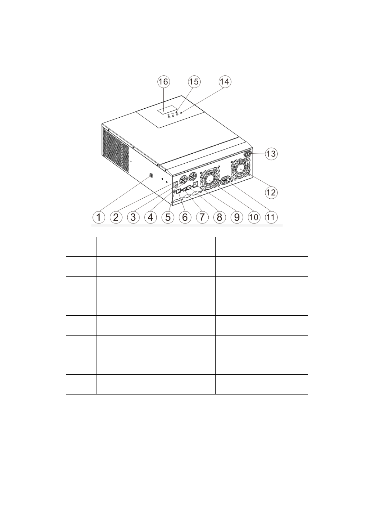
1.3 Product characteristics
Overload protector ⑨Dry contact port
②ON/OFF rocker switch ⑩Cooling fan
③ACi nput port ⑪Battery port
④AC output port ⑫Cooling fan
⑤Grounding screw hold ⑬PV port
⑥RS485-2 communication port ⑭Touch the key lightly
⑦USB communication port ⑮Indicator light
⑧RS485-1 communication port ⑯LCD screen
Solar Energy Storage Inverting & Control All-In-One Machine 6

1.4Dimension drawing
Solar Energy Storage Inverting & Control All-In-One Machine 7

2. Installation Instruction
2.1 Installation notice
Before installation, please carefully read the manual and get familiar with the installation step.
Take care while installing the battery. When installing the lead-acid liquid battery, it is required to wear
goggles. Any body part contacting the battery acid must be washed with clear water in time.
Don ’t place any metal object beside the battery to prevent short circuit of the battery.
Acid gas may be generated during battery charge. Therefore, it is required to ensure good ventilation
around the environment.
During cabinet installation, sufficient space shall be reserved around the all-in-one machine for heat
dissipation; do not install the all-in-one machine and lead-acid liquid battery in the same cabinet to avoid
the corrosion of the all-in-one machine by acid gas generated during battery operation.
Only the battery with type consistent with the all-in-one machine can be charged.
Loose connection points and corroded wires may cause great heat, thereby melting the insulation layer of
wires, burning the surrounding materials, or even causing fire. Therefore, all connectors must be tightened,
and the wires must be fixed with ties, so as to avoid the looseness of connectors caused by wire shaking
during mobile application.
Tie conductors are selected based on no greater than 5A/mm2current density.
The machine installed outdoors shall be protected against direct sunlight and rain.
After the power switch is turned off, there is still high voltage inside the all-in-one machine. Please do not
open or touch the internal components, and carry out relevant operation after the capacitor is fully
discharged.
Please do not install the all-in-one machine in a humid, greasy, flammable, explosive or dusty or other
severe environments.
The polarity of the battery input end of this product shall not be reversed, otherwise the device may be
damaged easily or there may be some unpredictable dangers.
AC supply input and AC output are both high voltage, so please do not touch the wires.
Do not touch the fan in working to prevent injury.
It is required to confirm that the all-in-one machine is the unique power supply input device for the load
device. It is forbidden to use the machine in parallel with other input AC power to avoid damage.
Solar Energy Storage Inverting & Control All-In-One Machine 8

2.2 Wire specification and breaker type
For wiring and installation ways,it is required to observe national and local electrical specification
requirements.
Recommended wiring specification and breaker type for photovoltaic array: the output current of the
photovoltaic array is affected by the form, connection way and illumination angle of photovoltaic array, therefore
the minimum wire diameterof the photovoltaic array is calculated based on the short circuit currentof
photovoltaic array. Please refer to the short circuit current value in the specification of photovoltaic array (the
short circuit current keeps unchanged for the photovoltaic arrays in series connection; the short circuit current
of photovoltaic arrays in parallel connectioni s the sum of short circuit currentof all components connected in
parallel); the short circuit current of the array cannot exceed maximumi nput currentof PV.
Please refer to the table below for PV input wire diameter and switch:
Type Recommended wire
diameter
Maximum PV input
current
Recommended types
of air switchor breaker
HF/MF4830S60-H 6mm2/10AWG 18A 2P—25A
HF/MF4850S80-H 6mm2/10AWG 18A 2P—25A
Note: the voltage in parallel shall not exceed maximum PV input open-circuit voltage.
Please refer to the table below for recommended AC input wire diameter and switch:
Type Recommended wire
diameter
Maximum bypass
input current
Recommended types
of air switchor breaker
HF/MF4830S60-H 10mm2/7AWG 40A 2P—40A
HF/MF4850S80-H 10mm2/7AWG
40A 2P—40A
Note: there is already a corresponding breaker at input connection point of mains supply. Therefore, no
breaker may be equipped.
Recommended input wire diameter and switch type for battery
Type Recommended
wire diameter
Rated
battery
discharge
current
Maximum
charge current
Recommended
types
of air switch or
breaker
HF/MF4830S60-H 20mm2/4AWG 85A 60A 2P—120A
HF/MF4850S80-H 30mm2/2AWG 125A 80A 2P—200A
Solar Energy Storage Inverting & Control All-In-One Machine 9
Recommended wire specification and breaker type for AC output
Type Recommended
wire diameter
Rated
inverter AC
output
current
Maximum bypass
output current
Recommended
types of air switch
or breaker
HF/MF4830S60-H 10mm2/7AWG 13A 40A 2P—40A
HF/MF4850S80-H 10mm2/7AWG 22A 40A 2P—40A
Note: the wire diameter is only for reference. In case of long distance between photovoltaic array and all-in-
one machine or between all-in-one machine and battery, use thicker wire to reduce voltage drop and improve
system performance.
Note: above wire diameter and breaker are only for reference. Please select appropriate wire diameter and
breaker based on practical condition.
2.3 Installation and Wiring
Installation step:
Step 1: confirm the installation position and heat dissipation space, confirm the installation position of all-in-
one machine, such as wall surface; to install the all-in-one machine, guarantee there is sufficient air flowing
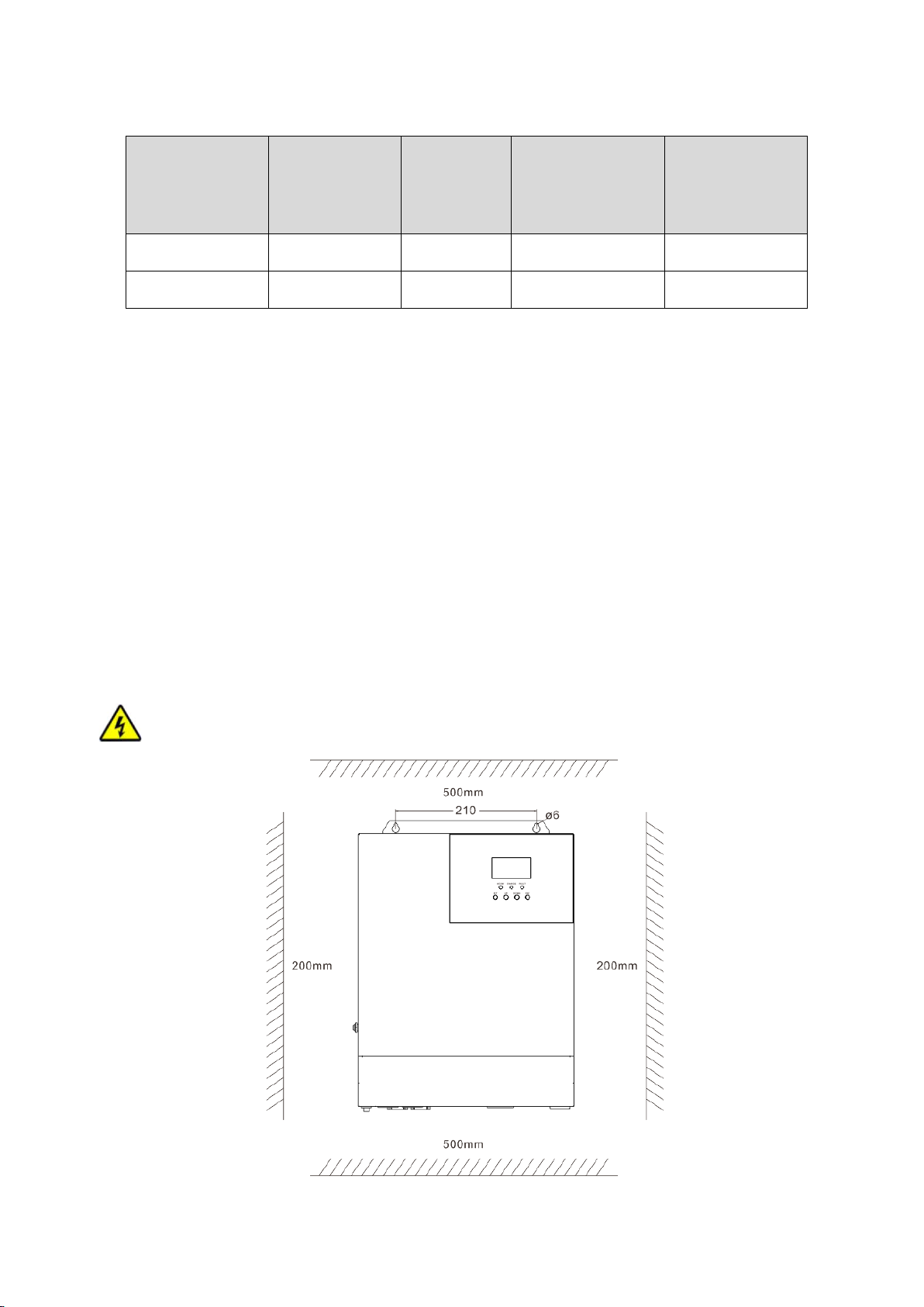
through the cooling fins of all-in-one machine. At least reserve 200mm space at the left and right air outlets of
the all-in-one machine to guarantee heat loss through natural convection. Refer to the overall installation
schematic above.
Warning: danger of explosion! Never install the all-in-one machine and lead-acid liquid battery into a
same sealed space or in a sealed place with probable accumulation of battery gas.
Solar Energy Storage Inverting & Control All-In-One Machine 10

Step 2: Remove the terminal protection cover
Step 3: wiring
AC input/output wiring method:
①Before AC input/output wiring, disconnect the external breaker at first and then confirm whether the cable
used is thick enough. Please refer to chapter “2.2 Wiring Specification and Breaker type”;
②Correctly connect AC input wire in accordance with cable sequence and terminal position shown in the figure
below. Please connect ground lead at first, and then live wire and mull wire;
Solar Energy Storage Inverting & Control All-In-One Machine 11
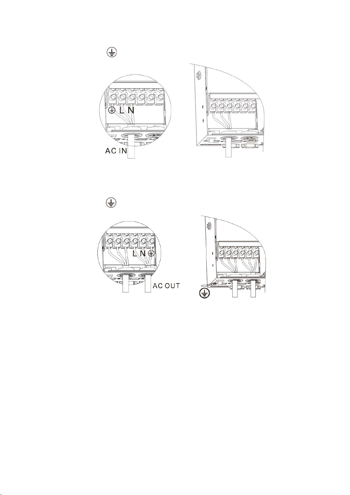
:Ground L:Live N:Neutral
③Correctly connect AC output wire in accordance with cable sequence and terminal position shown in the
figure below. Please connect the ground wire at first, and then live wire and null wire. The ground wire is
connected to the ground screw hold through Oshaped terminal.
:Ground L:Live N:Neutral
Note: use thick ground cable as far as possible (with cable section not less than 4mm2), place the ground point
to be close to the all-in-one machine as far as possible and choose shorter ground wire to the greatest extent
Wiring method of PV input:
Before wiring, disconnect external breaker at first, and confirm whether the used cable is thick enough.
Please refer to chapter “2.2 Wiring Specification and Breaker Type”;
②Correctly connect PV input wire in accordance with cable sequence and terminal position shown in the
figure below.
Solar Energy Storage Inverting & Control All-In-One Machine 12
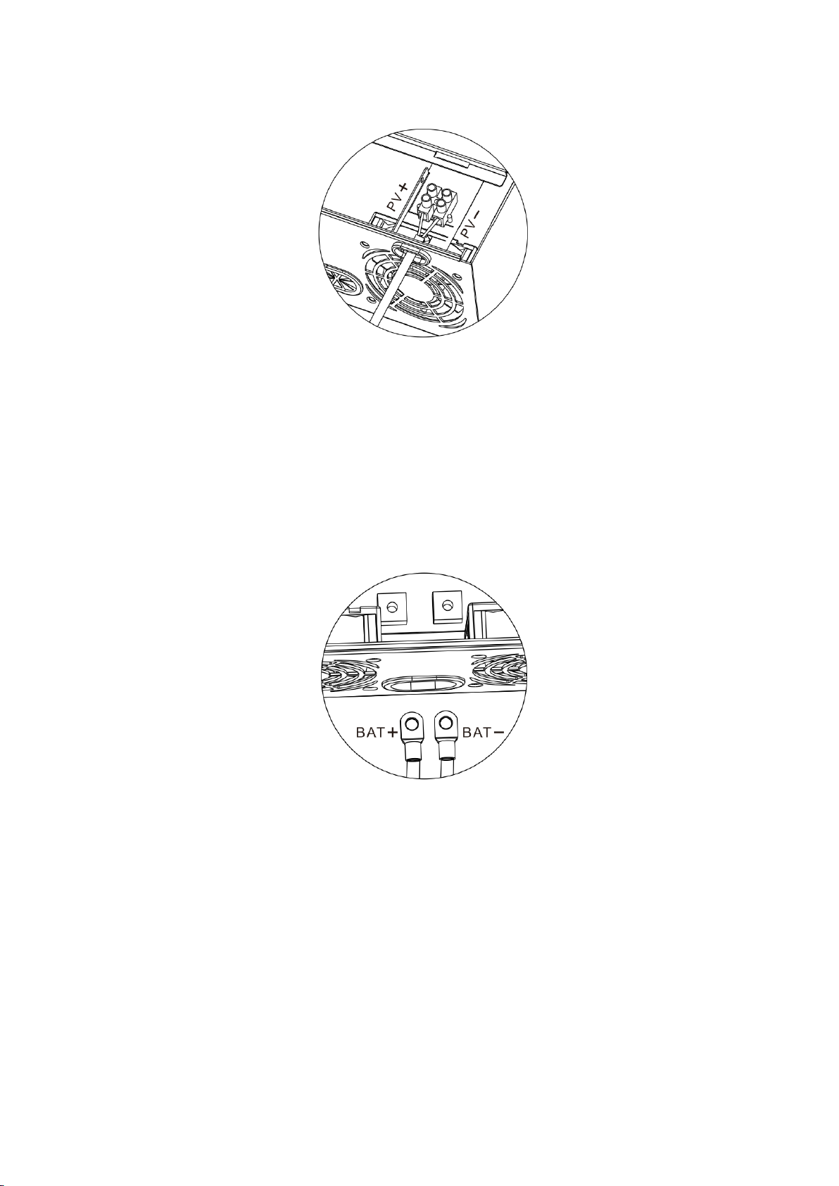
PV+ positive input pole PV1- negative input pole
BAT wiring method:
①Before wiring, disconnect external breaker at first, and then confirm whether the used cable is thick enough.
Please refer to chapter “ 2.2 Wiring Specification and Breaker Type ” . BAT wire shall be connected with
the machine via O-shaped terminal. It is recommended to use the O-shaped terminal with 5mm inside
diameter. The O-shaped terminal must compress BAT wire firmly to prevent excessive heating caused by
great contact resistance;
②Correctly connect BAT wire in accordance with cable sequence and terminal position shown in the figure
below.
BAT+: positive battery pole BAT-: negative battery pole
Warning notice:
①Input from mains supply, AC output and photovoltaic array may generate high voltage. Before wiring, make
sure to break the breaker or fuse;
②During wiring process, make sure to pay attention to the safety; during the wiring process, please don’t
close the breaker or fuse. At the same time, guarantee that “+” and “-” poles of different parts are
correctly connected with wires; a breaker must be installed at the battery end and selected based on chapter
“2.2 Wiring Specification and Breaker Type”. Before wiring, make sure to break the breaker to prevent
strong electric spark generated during wiring. At the same time, avoid battery short circuit during the wiring
process; if the all-in-one machine is in the area with frequent thunder, it is suggested to install an external
arrester at PV input terminal.
Solar Energy Storage Inverting & Control All-In-One Machine 13

Step 4: inspect whether the wires are correctly and firmly connected, especially whether the positive and
negative input poles of the battery are correct, whether the positive and negative input poles of PV are correct,
whether AC input is inaccurately connected to AC output terminal.
Step 5: install protective cap of terminal
Step 6: Start all-in-one machine
At first close the breaker at the battery end, and then press the rocker switch at the lower left side of the machine
to “ ON ” state, “ AC/INV ” indicator light flashes, indicating normal operation of inverter. Afterwards,
close breakers of photovoltaic array and mains supply. In the end, after AC output is normal, turn on AC load
one by one to avoid protection action generated by great instant impact owing to simultaneous turnon of loads.
The all-in-one machine operates normally in accordance with set mode.
Note: if power is supplied to different AC loads, it is suggested to turn on the loads with great impact current,
and then turn on the load with little impact current after the load operates stably.
Note: in case of abnormal operation of all-in-one machine or abnormal display of LCD or indicator light, refer
to Chapter 6 for troubleshooting.
Solar Energy Storage Inverting & Control All-In-One Machine 14

3.Operating Mode
3.1 Charge mode
1. Photovoltaic priority: in photovoltaic priority charge mode, mains charge is started only when photovoltaics
is out of work. Make full use of solar energy for power generation in the daytime and transfer to the mains
supply for charge to maintain electric quantity of the battery. It is suitable for areas with relatively stable power
grid and relatively expensive electricity price.
2. Mains supply priority: mains supply is to charge the battery preferentially and the photovoltaic charge can
be started only when the mains supply is valid.
3. Mixed charge: with mixed charge through photovoltaics and mains supply, photovoltaic MPPT charge is
used preferentially. In case of insufficient photovoltaic energy, the mains supply is used for supplement. In case
of sufficient photovoltaic energy, mains supply stops charge. Electricity can be charged fastest with the way,
which is suitable for the area with unstable power grid, so as to supply sufficient backup power supply at any
time.
4.Only solar: only photovoltaic charge is used, no mains supply is started. This way can save the energy at most.
The electric energies of battery are all from solar energy. This way is suitable for areas with good light condition.
Solar Energy Storage Inverting & Control All-In-One Machine 15

3.2 Output mode
Photovoltaic priority mode: Photovoltaic and battery supply power to the load. With diversified charge
mode and optional output mode, when photovoltaic priority mode is selected, the green solar energy can
be used as far as possible so as to achieve energy conservation and emission reduction. It switches to mains
supply when the photovoltaics is invalid. With the mode, solar energy can be used maximally and electric
quantity can be maintained at the same time. Therefore, the mode is suitable for areas with stable power
grid.
Mains supply priority mode: it only switches to inverter for power supply when mains supply is invalid,
equivalent to a backup UPS. Therefore, the mode is applicable to area with unstable power grid.
Inverter priority mode: it only switches to mains supply in case of undervoltage of battery. With the mode,
DC electric energy is used maximally. Therefore, it is applied to the area with stable power grid.
Mixed functions mode: When the battery is not available or the battery is fully charged, the load is
provided by PV and commercial power, PV maximum output power output。( Only used for MF)
Solar Energy Storage Inverting & Control All-In-One Machine 16

4. Operation Instruction for LCD Screen
4.1 Operation and display panel
4.2 Introduction to operation keys
Function Key Description
SET Enter/exit setting menu
UP Last option
DOWN Next option
ENT Confirm/enter option under setting menu
4.3 Introduction to indicator light
Indicator light Color Description
AC/INV Yellow
Constant on: mains supply output
Flashing: inverter output
CHARGE Green
Flashing: battery in charge
Constant on: charge completed
FAULT Red Constant on: fault state
Solar Energy Storage Inverting & Control All-In-One Machine 17
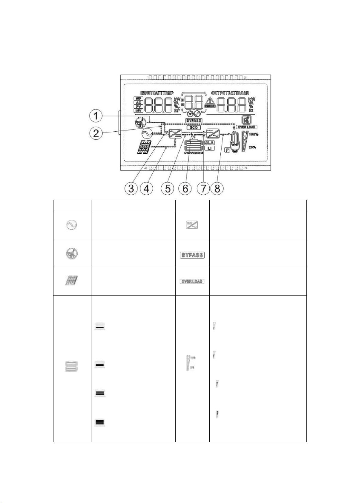
4.4 Introduction to LCD screen
Icon Function Icon Function
Indicating that AC input end
has been connected to
power grid Indicating that inverter circuit is in
working.
Indicates that the AC input
mode in APL mode (wide
voltage range) Indicating that the machine is in
mains supply bypass work mode
Indicating that PV input end
has been connected to solar
battery panel
Indicating that AC output is in
overload state
Indicating that machine has
been connected to battery,
indicating 0%~24%
battery remainin
capacity
indicating 25%~49%
battery remaining capacity
indicating 50%~74%
battery remaining capacity
indicating 75%~100%
battery remaining capacity
Indicating percentage of AC
output load,
indicating 0%~24% load
percentage,
indicating 25%~49% load
percentage,
indicating 50%~74% load
percentage,
indicating ≥75% load
percentage
Solar Energy Storage Inverting & Control All-In-One Machine 18

Indicating that present
battery type of the machine
is lithium battery Indicating that buzzer is not
enabled
Indicating that current
battery type of machine is
lead-acid battery Indicating alarm of machine
Indicating that the battery is
in charge state. Indicating that the machine is in
fault state.
Indicating that AC/PV
charge circuit is in working Indicating that the machine is in
setting mode.
Indicating that AC output
end has AC voltage output
Middle parameter display of screen,
1. In non-setting mode, displaying
alarm or fault code; 2. In setting
mode, displaying code of
parameter item under current
setting.
Parameter display at left side of screen: input parameter
Indicating AC input
Indicating PV input
Indicating inverter circuit
The icon is not displayed
Displaying battery voltage, total charge current of battery, charge power of
mains supply, AC input voltage, AC input frequency, PV input voltage,
temperature of internal radiator, software version
Parameter display at right side of screen: output parameter
Indicating output voltage, output current, output active power, output
apparent power, battery discharge current, software version; under setting mode,
displaying the setting parameter under the parameter item code set
currently
Arrow display
The arrow is not displayed ⑤Indicating charge from
charge circuit
to battery end
②Indicating power grid power supply
to load ⑥The arrow is not displayed
③Indicating power grid power supply
to charge circuit ⑦Indicating power supply
from battery
end to inverter circuit
④Indicating PV power supply to charge
circuit ⑧Indicating power supply
from inverter
circuit to load
Solar Energy Storage Inverting & Control All-In-One Machine 19

Real-time data view method
In LCD main screen, press keys “UP” and “DOWN” to turn page and view different realtime
data of the machine.
Page Left Parameter of Screen
Middle
Parameter of
Screen
Right Parameter of Screen
1 Battery input voltage
Fault code
Output voltage
2 PV temperature PV output KW
3 PV input voltage PV output current
4 Input battery current Output battery current
5 Input battery KW Output battery KW
6 AC input frequency AC output load frequency
7 AC input voltage AC output load current
8 Input voltage Output load KVA
9 INV temperature INV output load KW
10 APP software version Bootloader software version
11 Model Battery Voltage Rating Model Output Power Rating
12 Model PV Voltage Rating Model PV Current Rating
4.5 Setting parameter
Key operation description: to enter setting menu and exit from setting menu, please press key“SET”. After
entering the setting menu, parameter number【00】shall flash. At this time, press keys“ UP ”and“ DOWN ”
to select the parameter item code to be set. Afterwards, press key“ ENT” to enter parameter editing state. At
this moment, the parameter value can flash. The parameter values are adjusted through keys “UP” and
“DOWN”. In the end, press key“ENT” to complete parameter editing and return to parameter selection state.
Solar Energy Storage Inverting & Control All-In-One Machine 20
This manual suits for next models
3
Table of contents
Other Srne Batteries Charger manuals


