CTEK CHARGESTORM CONNECTED 2 User manual

USER MANUAL
MULTILINGUAL
MANUAL
CHARGESTORM® CONNECTED 2

2User & installation instructions CTEK E-Mobility AB
Content
CHARGESTORM® CONNECTED...... 2
Product description ...................... 2
Intended use.................................... 2
In the box................................................ 2
Overview................................................. 2
Status symbols............................... 3
To charge the vehicle......................... 4
Open access & RFID access ...... 4
To connect CHARGESTORM® CONNECTED
to the vehicle ................................... 4
To start charging with open access 4
To start charging with RFID access 4
Installation ............................................ 5
Introduction...................................... 5
Safety ................................................. 5
Optional equipment....................... 5
To check before installation....... 5
To prepare the location for installation 5
To install the charging station on a wall 5
To install the charging station on a pole 6
To do the cable installation ........ 6
To install the power cable ........... 6
To install the network cable and the 3G-modem
(optional)............................................7
To finish the installation ...............7
To change the configuration settings 8
To do a installation tests ............. 9
To do maintenance tests ............ 9
To recycle the product ................. 9
Technical data.....................................10
Intended use
This charging station is intended for wall-mounted or pole-mounted use.
The charging station is intended for both restricted and non-restricted locations.
In the box
1
2
34
5
6
7
8
9
10
1. The charging station CHARGESTORM® CONNECTED.
2. Two keys.
3. User and installation instructions.
4. Cover for cable inlet and cable glands (M25 and M12).
5. Holder for charging connector (for variants with fixed cable).
6. Insulation tube.
7. Four mounting screws.
8. Four rubber gaskets.
9. Four metal gaskets
10. Jumper (for variants with one phase)
Overview
1
2
3
4
5
6
1. Front panel.
2. Display with charging status symbols.
Overcurrent and short-circuit
protection ........................................10
Part specific data..........................10
CTEK E-Mobility warranty statement 11
Limited warranty ............................11
Circumstances that will void the limited warranty 11
Additional information..................11
National usage restrictions .......11
Copyright................................................11
Revisions...........................................11
Abbreviations .......................................11
Electrical schematics........................11
CHARGESTORM® CONNECTED
Product description
CHARGESTORM® CONNECTED is a multi usage station for electrical vehicles.
The charging station comes in several variants, such as for dierent output
power and number of outlets. For a complete list of article numbers, download
datasheet at www.ctekemobility.com.
NOTE: Refer to the top of the charging station for model information.
CHARGESTORM® CONNECTED 2 is an improved and updated version of our
advanced EV charger with a range of functions and built in safety features. It
has a powerful charge controller, which can handle dual type 2 outlets/charging
cables and oers load balancing support through NANOGRID™.
Overheating protection
At high temperatures the charging station's algorithm will determine the optional
current. This reduces the risk of overheating and damaging the charging station
without preventing the use of the device.

User & installation instructions 3
CTEK E-Mobility AB
EN
3. Back cover.
4. Technical box.
5. Electrical Vehicle outlet.
6. Electrical Vehicle outlet (fixed cable).
Status symbols
SYMBOL COLOR MODE EXPLANATION
Open RFID symbol not active.
Solid green RFID Waiting for RFID tag.
Flashing
Yellow
RFID Authentication in progress. Please wait!
Flashing
Green
RFID RFID tag approved. Charging will now
start.
Flashing
red once
RFID RFID tag access denied (user not
authorized for charging).
Solid green RFID/
Open
Available and ready for charging.
Flashing
green
RFID Waiting for cable connection or
authentication.
Solid Blue RFID/
Open
Vehicle connected but not charging (for
example, the vehicle is fully charged or
the charging session is paused).
Flashing
Blue
RFID/
Open
Charging in progress.
SYMBOL COLOR MODE EXPLANATION
Solid Red RFID/
Open
Alarm active. Most likely a fuse has
tripped. Open the technical box and
reset the fuse.
Outlet has a temporary fault. The fault
could be one of the following:
• Time limit for authentication reached.
• PP-signal cannot be read from cable
(Only applicable for type 2 outlet).
• Outlet motor could not lock cable.
Solid Blue - The charging station has connected to
cloud backend. Only displayed during
boot up. The flashing will take place for
5 seconds.
Solid Red RFID/
Open
The charging station has failed to
connect to the cloud backend during
start up. Only displayed during boot up.
NOTE: If the charging station has no active symbols, the charging station is
inactive. This may be because it has been configured in that way, because
the charging station is restarting, or because the charging station has been
deactivated for planned maintenance.

4User & installation instructions CTEK E-Mobility AB
To start charging with open access
1
2
To charge the vehicle
Open access & RFID access
A B
The charging station can operate in two dierent
authentication modes, open access (A) and RFID
access (B). Open access means that the charging
starts immediately when the vehicle is connected
to the charging station. RFID access means that the
charging does not start until a RFID tag has been
used for authentication. Some operators also oers
additional authentication, such as a mobile app.
NOTE: There are many dierent RFID formats.
Contact CTEK E-Mobility if your RFID tags are not
original CTEK E-Mobility RFID tags to make sure that
your RFID tags are compatible with the charging
station. The supported RFID standard is ISO1443A/
Mifare.
To connect CHARGESTORM®
CONNECTED to the vehicle
1
2
To start charging with RFID access
1
2
< 1 cm
3
4
5
6

User & installation instructions 5
CTEK E-Mobility AB
EN
Installation
Introduction
This part of the instructions shows how to install the
charging station CHARGESTORM® CONNECTED.
Safety
• Only an accredited electrician is allowed to
perform the installation described in this
document.
• Read and obey the instructions in this
document before installation and operation of
the product.
• Installation must fulfill local safety regulations.
• Do not use adaptors or conversion adapters
with this product, according to IEC61851
standard requirements.
• This charging station does not have ventilated
charging.
• Make sure the cables in the charging station
are not loose due to vibrations during
transport. If any cables are loose, reconnect
the cables and tighten the screws.
• The installation is recommended to be carried
out by two persons.
• Use safety shoes during installation.
Tools
Mini-USB
> 2000 mm
M8
!
• Mifare Classic/IEC 14443 Type A and
compatible RFID tag (in case RFID shall be
used).
• Computer/Laptop (OS: Linux or OSX is
recommended, Windows 10 requires USB
driver installation).
Optional equipment
• Pole mount kit for a pole diameter of 60 mm.
Article number 920-00010 (only if added).
• Pole mount kit for two boxes, to enable
maximum four EV connectors from one pole.
Article number 922-00018.
To check before installation
Do the checks that follow before you do the cable
installation.
1. Avoid installation of the EV charger in direct
sunlight. If the product is installed in direct
sunlight, symbol visibility is decreased and the
temperature of the product increases. This will
trigger the overheating protection and limiting
the charging current.
2. Decide if the unit should be installed outdoors
or indoors.
a For outdoor installation, the power cable
and network cable are recommended to be
installed from below to prevent water from
entering the technical box from the top.
b. For indoor installation, the power cable and
network cables can be installed either from
the top or from the bottom of the technical
box.
NOTE: For installations with a power cable
diameter greater that 17 mm, the power
cable must be installed from below.
To prepare the location for
installation
1. Decide mounting position of the charging
station.
a. Make sure that there is enough space
available for normal operation.
12-24 kg
Min
350 mm
Min
300 mm
1100-
1500 mm
500-
1500 mm
b. For installation on a wall, make sure that the
wall material is suitable for mounting of the
box. The wall must withstand the weight of
the charging station.
c. For installation on a pole, refer to the
manual for the pole mount kit.
To install the charging station on a
wall
209.5
160
246
43
[mm]
1. Locate the four screw holes in the back cover.
2. Drill four holes in the wall that align with the
holes in the back cover.
3. Unlock and open the technical box with the key.
4. Remove the protection cover.

6User & installation instructions CTEK E-Mobility AB
!
5. Install the charging station on the selected
location with the rubber gaskets first and then
the washer and the four M8 screws.
CAUTION: Do not install the charging station without
the rubber gaskets. Otherwise it can leak in water
and cause damage to the EV charger.
6. Make sure that the charging station is firmly
installed on the wall.
7. Make sure to cover all open holes with silicon or
rubber gaskets to protect the charging station
against water.
Min
500 mm C CBA
ABC
L1 L2 L3 N PE
CB
A
ABC
L1 L2 L3 N PE
L1
L1
L2
L2
L3
L3
N
N
PE
PE
L1 L2L3 NPE
18-20 mm
2. Make sure that the protected ground wire is
longer than the other wires so that it will be the
last wire to detach if it is pulled.
3. Strip the wires approximately 18-20 mm at the
end of the power cable. The cross-sectional
area of the power cable must not exceed 16
mm2. Follow the instructions on the previous
page.
4. Connect the supply wires to the terminal
blocks.
NOTE: The terminal blocks are of push-in type. Make
sure that the cables are properly connected.
NOTE: For regional dierences of the grounding
system, such as IT-Nett, refer to the supply input
schematic on page 13.
To install the charging station on a
pole
• For installation on a pole, refer to the manual
for the pole mount kit.
To do the cable installation
1. Make sure that the power is o.
AA 16 mm2
2. Make sure that the cable installation is
dimensioned (A) for the charging station.
CAUTION: The cable glands must be replaced if the
cables are outside this specified range.
+
3. If the power cable and network cable should
be installed from below or from the back, drill
holes in the unit according to the illustration.
CAUTION: Make sure not to damage the
content inside the unit when you drill the holes.
4. Install the cable glands in the holes to protect
the unit from dust and water penetration.
NOTE: The cable gland for the power cable that
is delivered with the product supports cable
dimensions between 11-17 mm and the gland for the
network cable supports cable dimensions 3-6 mm.
5. If the power cable and network cable are
installed from the top, there are two holes on
the top of the unit. Install the power cable to
the larger hole (M25) and the network cable to
the smaller hole (M12).
To install the power cable
1. Pull the power cable through the cable gland.

User & installation instructions 7
CTEK E-Mobility AB
EN
To install the network cable and the
3G-modem (optional)
B
C
D
E
G F
A
AController board
BRJ45
CUSB
DMini-USB
E3G-modem
FU.FL Antenna
contact
GSIM-card slot
If the charging station shall be connected to
NanoGridTM - Load balancing, or to the Charge Portal
- The cloud based charging portal online, do the
steps that follow.
• Enclose the network cable with the attached
insulation cable. The network cable in the
powerbox needs extra insulation for electrical
safety reasons.
• If the charging station is behind a firewall and
will be connected to a backend system, open
DNS (port 53) and https/wss (port 443) in
the firewall. Open ftp to allow remote firmware
upgrades.
• If Ethernet shall be connected, use a network
cable of type Cat5 or better. Connect the
network cable to the RJ45 connector on the
control board. The control board is located
on the front panel. When the network cable
is connected the activity LED in the RJ45
connector activates.
Mini SIM
15x25mm
• If 3G shall be connected, install an activated
SIM card in the charging station. The PIN
must be disabled and the subscription with
recommendation of a minimum of 2 GB/
month depending on the OCPP protocol
communication from the operator. Make sure
that the antenna cable is attached in both
ends.
NOTE:Some operators have installed the SIM card
at the factory.
To finish the installation
1. Install the protection cover.
2. Close and lock the technical box with the key.
3. Put the cover on the key lock.
4. Turn on the power from the distribution panel.
NOTE: It may take one to two minutes for the charger
to start.

8User & installation instructions CTEK E-Mobility AB
5. Make sure that the green connector symbol on
the front panel activates.
To change the configuration settings
NOTE: For most installations no change of the configuration is needed.
NOTE: CTEK E-Mobility recommends that the installation technician documents
the result of the configuration tests in the dedicated protocol.
1. If the computer runs on Microsoft Windows, Download the CCU Drivers
from the webbsite. Follow the instructions given on the webbsite.
NOTE: For Linux, Android and Mac OSX, the USB driver is part of the operating
system.
2. Connect the USB cable between the computer and the mini USB port on
the controller board.
3. Open the web browser and log in to the local web interface at
http://192.168.7.2
The user name and password are both “ccu”.
NOTE: CTEK E-Mobility recommends web browser Chrome for this action.
To configure the network interface (Ethernet)
2
3
4
1
5
1. Navigate to Configuration>Interface>General and select WAN = Wire.
2. Navigate to Configuration>Interface.
3. Select Wire.
4. Select DHCP or Static. If Static is selected, also enter IP address, netmask
and gateway.
5. Press Save at the bottom of the page.
To configure WWAN (3G)
2
3
4
1
5
NOTE: WWAN is a specific 3G mode and is usually more robust than PPP.
1. Navigate to Configuration.
2. Select Interface.
3. General and select WAN = modem (WWAN)
4. Navigate to Configuration>Interface>WWAN and enter APN applicable for
the selected 3G operator. Leave remaining fields empty.
5. Press Save at the bottom of the page.

User & installation instructions 9
CTEK E-Mobility AB
EN
To configure PPP 3G/4G
2
3
4
1
5
1. Navigate to Configuration.
2. Select Interface.
3. General and select WAN = modem (PPP).
4. Navigate to Configuration>Interface>PPP modem and enter APN applicable
for the selected 3G/4G operator. Leave remaining fields empty.
5. Press Save at the bottom of the page.
To configure current limit
2
1
3
NOTE: Change the settings of the current limit if the current limit must be lower
that the charging status fuse level.
1. Navigate to Configuration.
2. Select Outlet.
3. Change the settings for the current limit.
To configure URL and charging station identity (ChargeboxID) to the
portal
1. Do a check of the status page to make sure that the internet access op-
erates correctly.
2. Make sure that the OCPP ChargeboxID and server address is known. This
information should be provided by the portal operator. If CTEK E-Mobility's
portal “Charge Portal” is used, the URL to the portal has the format that
follows: wss://<companyname>.oamportal.com/Ocpp/websocket.
NOTE: The ChargeboxID must be unique and not contain more than 22
characters. The selected portal must support OCPP v1.5 or v1.6.
3. Navigate to Configuration>Backend and enter the ChargeboxID.
4. Set the communication protocol to OCPP v1.5 or v1.6.
5. Enter the backend address. Usually the other parameters may remain
unchanged.
6. Press Save at the bottom of the page.
7. Navigate to the status page and verify that the portal communication is
established.
To configure RFID
2
3
1
NOTE: For chargers without portal connection you can only add and remove RFID
tags from the web interface in the charger. For connected chargers you can only
change in the portal.
1. Navigate to Configuration>Outlet>Authentication and select RFID for all
outlets to activate RFID authentication with RFID tag before charging.
2. Add and delete approved RFID tags under Tag admin.
To do a installation tests
• Make sure that the charging station is firmly mounted on the wall/pole.
• Check the connection of the power cable and network cable. Tighten the
cable gland if it is necessary.
• If the installation is a Nanogrid Home setup, check the Communication
between the external EM and the Charger
• Charge a vehicle. Check the current and make sure that charging symbols
on the display operate correctly.
- Function control RFID
- Internet connection (3G/4G/Router/Ethernet)
• Make sure that the weather protection of the lock is sealed correctly.
• Make sure that the display is lit.
To do maintenance tests
Maintenance on the product must be done once a year.
• Ensure that the charging outlet/charging cable is in good condition.
• Replace the charging outlet/charging cable if it is necessary.
• Check the rubber gaskets. Remove any possible dirt from the rubber
gasket.
• If necessary, update the software.
• Check the cable gland. Tighten if it is necessary.
To recycle the product
The product must be recycled as electronic equipment. Follow the local
requirements for recycling of electronic equipment.

10 User & installation instructions CTEK E-Mobility AB
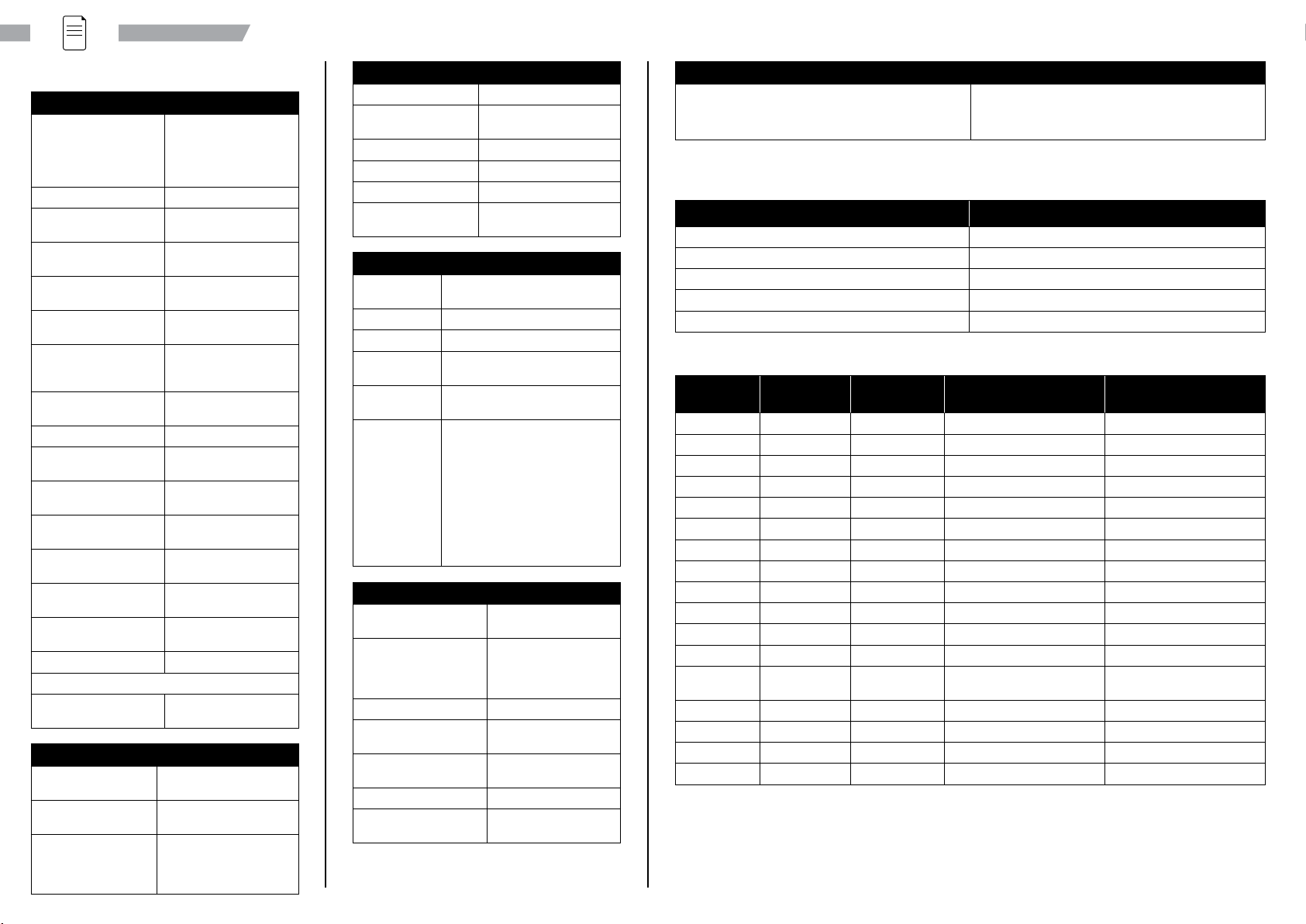
Technical data
POWER
Power input TN-S: 230/400 V AC
50Hz
IT: 230 V AC 50Hz
Max 63 A (depends on
model)
Power output AC
Connected to AC supply
network
Yes
Permanently connected
to the mains
Yes
Charging current Up to 32A (depends on
model)
Supply Connection TN-S: L1,L2,L3,N,PE
IT: L1,L2,PE
Fuses C-Characteristics.
Breaking capacity 6kA
Mode 3: 32A
Standby-usage
consumption
18-20 W
Rated frequency, fn50 Hz
Rated diversity factor,
RDF
1
Rated insulation
voltage, Ui
250/400 V
Rated impulse
withstand voltage, Uimp
4 kV
Rated peak withstand
current, Ipk
6 kA
Rated short-time
withstand current, Icw
6 kA
Max prospective short-
circuit current, Icp
6 kA
Overvoltage category III
Technical data for RCD
Rated making and
breaking capacity, Im
200 A
MECHANICS
Weight Up to 24kg (depends on
model)
Dimension
H x W x D
449x 282x 160mm
Material Front and back cover
in ABS plastic. Colored
zinc oxide metal box for
electronics.
MECHANICS
Ingress Protection IP54
Ambient operation
temperature
-30°Cto+50°C
Altitude < 2000m
Relative humidity Up to 100% at +25°C
Storage temperature -30°C to +50°C
External mechanical
impact
IK10
INTERFACES
EV connector One or two outlets Type 2 or
fixed cable of Type 1 or Type 2
Display LED symbols
Enclosure lock Mechanical lock with key.
Energy meter Internal or MID-approved
depending on option.
RFID tag
standard
Milfare 1k, Milfare 1k+, Milfare
Classic.
Connectivity 3G: Frequency band:
00/850/900/1700/1800/
1900/2100 MHz, Power class
3: +24 dBm, Power class 4:
+21dBm (EN 301 908-2 v11.1.1).
4G: Frequency band: LTE Cat-1,
B3 B8 B20 power class: 23dBm.
Fallback GSM/GPRS/EDGE
900MHz (Max: 2W) 1800 MHz
(Max: 1W).
COMPATIBILITY
Compliance IEC 61851-1, IEC 62196-
2, IEC 61439-7, CE
Approval Download the
Declaration of
Conformity from
www.ctekemobility.com
Charging method Mode 3
Electric shock
protection
Class I equipment
Communication
protocol
OCPP 1.5 and 1.6
Pollution degree 3
Intended for use in EMC
Environment
B
SAFETY
Ground fault detection Residual Current Device of type A. 30 mA.
DC-detector. 6 mA.
Overcurrent and short-circuit
protection
PROPERTY VALUE
Rated current, InSee part specific data
Characteristic C
Rated short-circuit capacity, Icn 6 kA
Rated service short-circuit breaking capacity, Ics 7.5 kA
Let-through energy, I2t 36000 A2s
Part specific data
ART.NO RATED
VOLTAGE, Un
RATED
CURRENT, InA
LEFT OUTLET RIGHT OUTLET
910-17049 230 V 16 A - Outlet, 1 ph, 230 V, 16 A
910-17062 230 V 32 A - Outlet, 1 ph, 230 V, 32 A
910-17050 230/400 V 16 A - Outlet, 3 ph, 230/400 V, 16 A
910-17028 230/400 V 32 A - Outlet, 3 ph, 230/400 V, 32 A
910-17045 230 V 16 A - Cable, 1 ph, 230 V, 16 A
910-17046 230 V 32 A - Cable, 1 ph, 230 V, 32 A
910-17047 230/400 V 16 A - Cable, 3 ph, 230/400 V, 16 A
910-17048 230/400 V 32 A - Cable, 3 ph, 230/400 V, 32 A
910-17042 230/400 V 16 A Cable, 1 ph, 230 V, 16 A Outlet, 1 ph, 230 V, 16 A
910-17051 230/400 V 16 A Outlet, 1 ph, 230 V, 16 A Outlet, 1 ph, 230 V, 16 A
910-17063 230/400 V 32 A Outlet, 1 ph, 230 V, 32 A Outlet, 1 ph, 230 V, 32 A
910-17059 230/400 V 32 A Outlet, 3 ph, 230/400 V, 16 A Outlet, 3 ph, 230/400 V, 16 A
910-17060 230/400 V 64 A Outlet, 3 ph, 230/400 V,
32 A
Outlet, 3 ph, 230/400 V, 32 A
910-17040 230/400 V 16 A Cable, 1 ph, 230 V, 16 A Cable, 1 ph, 230 V, 16 A
910-17091 230/400 V 32 A Cable, 1 ph, 230 V, 32 A Cable, 1 ph, 230 V, 32 A
910-17086 230/400 V 32 A Cable, 3 ph, 230/400 V, 16 A Cable, 3 ph, 230/400 V, 16 A
910-17092 230/400 V 64 A Cable, 3 ph, 230/400 V, 32 A Cable, 3 ph, 230/400 V, 32 A

User & installation instructions 11
CTEK E-Mobility AB
EN
CTEK E-Mobility warranty
statement
Limited warranty
CTEK issues a limited warranty to the original
purchaser of the product. Depending on the product,
the limited warranty period will vary. The limited
warranty is not transferable. The warranty applies
to manufacturing faults and material defects. The
warranty is void if the product has been handled
carelessly or repaired by anyone other than CTEK
or its authorized representatives. CTEK makes
no warranty other than this limited warranty and
is not liable for any other costs other than those
mentioned above, i.e. no consequential damages.
Moreover, CTEK is not obligated to any other
warranty other than this warranty.
Circumstances that will void the
limited warranty
If the seal of the product is broken, purposely
damaged, or in any way modified or altered; including
cables, electronics, mechanics or other parts of the
product; products that have been repaired by anyone
other than CTEK or its authorized representatives;
products that have been subject to the use of
supplies and accessories other than those approved
in writing or supplied by CTEK; improper use or
non-compliance with installation, commissioning,
operation or maintenance instructions (i.e. not
according to the operation and installation manual);
unauthorized modifications, changes or attempted
repairs; vandalism, destruction through external
influence and/or persons/animals; failure to observe
applicable safety standards and regulations; faults
caused by fire, water, snow, moisture, or other liquids
except as specified for normal use; products where
the serial number is defaced, altered or removed;
any utilization of a product that is inconsistent with
either the design of the product or the way CTEK
intended the product to be used; any installation
and/or modifications that prevent normal service
of the product; normal wear and tear and cosmetic
damage such as, but not limited to, corrosion,
scratches, dents, rust, stains, non-functional parts
such as, but not limited to, plastics and finishes;
damage, fault, failure and/or imperfection caused by
abuse, tampering, illegal use, negligence, prolonged
use or operation; or faults in any other way caused
by the customer/retailer/user.
Additional information
CTEK makes no other warranty than as set out
herein and CTEK shall in no event be liable for any
indirect or consequential damages. The faulty
product shall be returned with the receipt to the
retailer/place of purchase together with a fault
description. Goods returned to CTEK will be at CTEK’s
Abbreviations
• APN Access Point Name.
• CP Control Pilot.
• CCU Charge Controller Unit
• DHCP Dynamic Host Configuration Protocol.
• OCL Outlet Controller Light.
• OCPP Open Charge Point Protocol.
• PP Proximity Pilot.
• PPP Point to Point Protocol.
• RFID Radio Frequency Identification.
• WWAN Wireless Wide Area Network.
Electrical schematics
01 A ...........................................................11
01 B..........................................................12
01 C..........................................................13
CCU..........................................................14
3G/RADIO MODEM ............................14
CAB10 .....................................................14
3PH OUTLET LEFT .............................15
1PH OUTLET LEFT...............................15
3PH CABLE LEFT................................15
1PH CABLE LEFT.................................16
3PH OUTLET RIGHT...........................16
1PH OUTLET RIGHT............................16
3PH CABLE RIGHT ............................. 17
1PH CABLE RIGHT ..............................17
OCL ..........................................................17
discretion and only valid with an approved Return
Material Authorisation (RMA) Reference Number
issued by CTEK to the purchaser. Products sent
directly to CTEK without an RMA will be returned to
the sender at the sender’s cost. The warranty period
for a product is stated in the applicable product user
manual supplied with the product. The warranty is
only valid if the warranty period has not expired.
If the warranty claim of a faulty product is not
approved by CTEK, the product will be returned only
if the sender explicitly so requests. The customer/
retailer/place of purchase will pay the freight.
Faulty products will be repaired, or replaced with an
exchangeable product, and returned at CTEK’s cost.
If the warranty period has expired, the product will
be returned without further investigation at the cost
of the customer/retailer/place of purchase. Faulty
products will be scrapped by CTEK if deemed not
repairable. CTEK reserves the right to vary, modify
or change the terms and conditions herein due to
change(s) in availability of services, products and/
or spare parts, or for the purpose of complying
with applicable policies, rules, regulations and law,
without notice.
National usage restrictions
Some countries, states or provinces have other
electrical codes and standards than stated in this
manual. The installation and usage of the product
shall follow local regulations. The product is intended
for use by general public. The product is intended
for locations with both restricted access and non-
restricted access.
This product is only allowed for use in the following
regions: CZ, DE, DK, GR, ES, FI, FR, IS, NL, NO, PL, SE,
UK, AT, BE, CY, IE, LU and MT.
Copyright
These instructions are delivered “as is” and contain
content that can change without prior notice. CTEK
E-Mobility AB does not guarantee that everything is
correct in the instructions. CTEK E-Mobility AB is not
responsible for faults or incidents or damage that
is caused by not following the instructions in this
manual.
© Copyright CTEK E-Mobility AB 2019. All rights
restricted. Copying, adaption or translation of these
instructions are strictly forbidden without written
approval by CTEK E-Mobility AB, except what is
regulated by copyright laws.
Revisions
The descriptions, information and specifications
contained in this manual were in eect at printing.
To make sure that the maintenance instructions are
complete and up to date, always read the manual
published on our website.

12 User & installation instructions CTEK E-Mobility AB
X
Energy Meter
Energy Meter
2016-1301
2016-1301
2016-1301
2016-1304
Curve C 32A
Curve C 32A
OCL Left
OCL Right
CAB13
X9
W1 BN 6
W2 BN 6
W3 BK 6
W5 GY 6
W4 BK 6
W6 GY 6
W8 BU 6
W15
BU
1.5
W11 BK 6
W12 BK 6
W13 BK 6
W19 BU 6
W27 BK 6
W28 BK 6
W29 BK 6
W33 BU 6
CAB14
W46 BK 1.5
W47 BU 1.5
X16
Distr.
Rail
X15
Distr.
Rail
J1*
W16 BK 6
W17 BK 6
W18 BK 6
W30 BK 6
W31 BK 6
W32 BK 6
W14
BU
1.5
W16-W18
have ferrules
here
¤
¤
¤
¤
¤
¤
¤
W30-W32
have ferrules
here
¤
EM1
EM2
X6 X7 X8
X1
X1
X2
X2
X3
X3
X4
X4
F1
F2
U3C
U4C
1
2
3
4
5
6
L1
L2
L3
1
2
3
4
5
6
N
N
L1
L2
L3
1
2
3
4
5
6
N
N
1
2
3
4
5
6
1U2U
3U4U
5U6U
2L
4L
6L
1L
3L
5L
1U2U
3U4U
5U6U
2L
4L
6L
1L
3L
5L
1
2
J302
3
4
5
L1P
6
L1N
L2P
L2N
L3P
L3N
1
2
J302
3
4
5
L1P
6
L1N
L2P
L2N
L3P
L3N
Optional Optional
Optional Optional
Heater
Optional
Choose one of two options,
Energy Meter: X15, EM1 & W11-W14 or
Transformer: CAB13 & W16-W18.
Choose one of two options,
Energy Meter: X16, EM2 & W15, W27-W29 or
Transformer: CAB14 &W30-W32.
OR
OR
L1
N
SUPPLY INPUT
L2
L3
L1
L2
no
connect
L3
230V~ 400V~
to-line
Line-Line-
to-line
IT-
nett
TN-
system
no
connect
no
connect
N
L1
230V~
Single
phase
LEFT
RIGHT

User & installation instructions 13
CTEK E-Mobility AB
EN
DF11
Contactor
Contactor
DF11
OCL Left
OCL Right
SNUBBER
SNUBBER
CAB6
CAB7
W20 BK 1.5
W21 BU 1.5
W54 BK 1.5
W34 BK 1.5
W35 BU 1.5
W36 BK 1.5
L1
L2
L3
N
L1
L2
L3
N
W53 BK 1.5
W26 BK 1.5
W59 BU 1.5
W60 BU 1.5
W56 BK 1.5
W55 BK 1.5
W22 BK 6
W23 BK 6
W24 BK 6
W25 BU 6
W38 BK 6
W40 BU 6
W39 BK 6
W37 BK 6
W57 BK 1.5
W58 BK 1.5
K1
K2
U3A
U4A
P42
P41
U5
U6
RC2
RC1
1
2
3
4
5
6
7
8
1
2
3
4
5
6
7
8
9
10
2
4
1
3
65
A1 A2
87
2
4
1
3
65
A1 A2
87
1
2
3
4
5
6
7
8
1
2
3
4
5
6
7
8
9
10
1
2
J301
3
1
2
3
4
5
6
7
8
9
10
J502
TEST
ERR
X6
X30
GND
VCC
PWM
NC
LOW
HIGH
4
5
6FUSE_FB
RELAY_OUT
NEUTRAL
L1_IN
L2_IN
L3_IN
1
2
J301
3
1
2
3
4
5
6
7
8
9
10
J502
TEST
ERR
X6
X30
GND
VCC
PWM
NC
LOW
HIGH
4
5
6FUSE_FB
RELAY_OUT
NEUTRAL
L1_IN
L2_IN
L3_IN
1
2
3
4
5
6
1
2
3
4
5
6
1
2
J1001
TEST
3
4
5
6
7
8
ERR
X6
X30
GND
VCC
PWM
NC
1
2
J1001
TEST
3
4
5
6
7
8
ERR
X6
X30
GND
VCC
PWM
NC
Phase
rotation
See
next
page
See
next
page
Used by Dual output models.
Wire used for models with 3ph output.
LEFT
RIGHT
BK=black
BN=brown
BU=blue
GN=green
GY=grey
OG=orange
PK=pink
RD=red
TQ=turquoise
VT=violet
WH=white
YE=yellow
YEGN=yellow-green
* Jumper J1 is needed
to run with single phase
input. P/N 2016-403.
Ferrule

14 User & installation instructions CTEK E-Mobility AB
Power Supply
EM Left (Always)
EM Right (dual models)CCU
2016-1307
OCL Right (dual models)OCL Left (always)
CAB12
CAB4
CAB5 CAB11*
W7 BU 1.5
W9 YEGN 1.5
W10 BK 1.5
* For external MBUS connection
CAB11 is replaced by the external cable.
U2
P1
EM1A
EM2A
U1A
X5
U4BU3B
1
2
1
2
K1
3
4L
N
PE
1
2
K2
1
2
K3
AC/DC
24
230
1
2
1
2
3
4
3
4
2
1
3
4
2
1
3
4
2
1
3
4
2
1
3
4
2
1A
B
GND
9
8
10
7T
120R
A
B
GND
9
8
10
7T
120R
1
2
1
2
B2
A2 1
2
J6
1
2
GND
J29
+24V
RTN
B
A
4
3
J305
+24V
1
2
4
3
2
1
4
3
1
2
A
B
J304
J306
ADDR
B
A
4
3
J305
+24V
1
2
4
3
2
1
4
3
1
2
A
B
J304
J306
ADDR
EARTH
Used by Dual output models.
Optional and only used
by Dual output models.

User & installation instructions 15
CTEK E-Mobility AB
EN
U1
1
2
1
2
1
2
1
2
1
2
1
2
1
2
1
2
1
2
3
4
1
2
3
4
1
21
2
1
2
1
2
1
2
1
2
1
2
1
2
1
2
1
2
1
2
1
2
1
2
1
2
1
2
1
2
1
2
1
2
LOCKFB1
LOCKFB2
GND10R
PP2
GND10R
PP1
+12V
CONS1
CONS2
+12V
M1+LOCK
M1+UNLOCK
M2+LOCK
M2+UNLOCK
+12V
+12V
PULSE1
PULSE2
CT1+
CT1-
CT2-
CT2+
CT3-
CT3+
CT4-
CT4+
CT5-
CT5+
CT6-
CT6+
CP1
CP2
+24V
RTN
GF/CFB2
GF/CFB1
FFB2
FFB1
N
GND
GND
GND
GND
+24V
RLY1
RLY2
B1-
A1+
SDA
SCL
B2-
A2+
ETH
USB HOST
USB DEVICE
+12V
+12V
RD2
GN2
BU2
RD1
GN1
BU1
J32
J31
J33
J23
J24
J5
J6
J4
J30
J7
J8
J1
J3
J2
J29
J16
J17
J18
J19
J20
J21
J22
J25
J26
J12
J13
J27
J28
J15
J14
J11
RFID1
RFID2
J5
J6
RFID
RS485
RS485
RS485
GCUSTATION
CCU
1v98 & higher
CCU
CCU
CCUModem
U.FL.
Antenna
CAB18
U1
CU
1DU8
P11
U9
1
2
JP4
3
4
+24V
GND
1
2
JP2
GND
+3V3
1
2
JP9
GND
+3V3
1
2
JP7
3
4
JP3
5
6
7
8
9
10
1
2
3
4
5
6
7
M_TX
M_RX
+3V3
HDPB
HDMB
M_RESET
ON/OFF
SCLK
GND
MOSI
MISO
SEL
Z_RESET
IRQ
1
2
3
4
5
6
7
8
9
10
1
2
3
4
5
6
7
1
2
3
4
1
2
1
2
J7J4
J2
J9
J3
RADIO
MODEM
J11
3G/4G/RADIO MODEM
UI Board
CCU
CAB10
U7
U1B
1
2
3
4
1
2
1
2
3
4
1
2
3
4
SCL
SDA
GND
+12V
1
2
J7
+12V BU1
3
4
GN1
RD1
1
2
J4
GND
1
2
J30
SCL
SDA
+24V 1
2
CAB10

16 User & installation instructions CTEK E-Mobility AB
Lock Solenoid
Outlet
OCL Left
CAB8
L1
L2
L3
N
W22 BK 6
W23 BK 6
W24 BK 6
W25 BU 6
W41
YEGN 6
U3D
X11
M1
OUT1
1
2
3
4
5
6
7
8
L1
L2
L3
N
PE
CP
PP
1
2
J503
3
4
5
6
7
8
CP
PP
GND
GND
SOL LOW
SOL SENS
12V
12V
3PH OUTLET LEFT
Lock Solenoid
Outlet
OCL Left
CAB8
L1
N
X11
W22 BK 6
W25 BU 6
M1
OUT1
U3D
W41
YEGN 6
1
2
3
4
5
6
7
8
L1
L2
L3
N
PE
CP
PP
1
2
J503
3
4
5
6
7
8
CP
PP
GND
GND
SOL LOW
SOL SENS
12V
12V
1PH OUTLET LEFT
Cable
OCL Left
L1
L2
L3
N
OUT1
X11
U3D
CAB15
X13
L1
L2
L3
N
PE
CP
1
2
3
4
5
6
7
8
1
2
J503
3
4
5
6
7
8
CP
PP
GND
GND
SOL LOW
SOL SENS
12V
12V
3PH CABLE LEFT

User & installation instructions 17
CTEK E-Mobility AB
EN
Cable
OCL Left
L1
N
OUT1
X11
U3D
CAB15
X13
L1
L2
L3
N
PE
CP
1
2
3
4
5
6
7
8
1
2
J503
3
4
5
6
7
8
CP
PP
GND
GND
SOL LOW
SOL SENS
12V
12V
1PH CABLE LEFT
Lock Solenoid
Outlet
OCL Right
CAB9
L1
L2
L3
N
W37 BK 6
W38 BK 6
W39 BK 6
W40 BU 6
W42
YEGN 6
U4D
X12
M2
OUT2
1
2
3
4
5
6
7
8
L1
L2
L3
N
PE
CP
PP
1
2
J503
3
4
5
6
7
8
CP
PP
GND
GND
SOL LOW
SOL SENS
12V
12V
3PH OUTLET RIGHT
Lock Solenoid
Outlet
OCL Right
CAB9
L1
N
X12
W37 BK 6
W40 BU 6
M2
OUT2
U4D
W42
YEGN 6
1
2
3
4
5
6
7
8
L1
L2
L3
N
PE
CP
PP
1
2
J503
3
4
5
6
7
8
CP
PP
GND
GND
SOL LOW
SOL SENS
12V
12V
1PH OUTLET RIGHT
50023065B

18 User & installation instructions CTEK E-Mobility AB
Cable
OCL Right
L1
L2
L3
N
OUT2
X12
U4D
CAB16
X14
L1
L2
L3
N
PE
CP
1
2
3
4
5
6
7
8
1
2
J503
3
4
5
6
7
8
CP
PP
GND
GND
SOL LOW
SOL SENS
12V
12V
3PH CABLE RIGHT
Cable
OCL Right
L1
N
OUT2
X12
U4D
CAB16
X14
L1
L2
L3
N
PE
CP
1
2
3
4
5
6
7
8
1
2
J503
3
4
5
6
7
8
CP
PP
GND
GND
SOL LOW
SOL SENS
12V
12V
1PH CABLE RIGHT
U3/U4
J501
J306J305
J502J503
J304
J301
6
5
4
3
2
1
J302
OCL
L3_IN
L2_IN
L1_IN
NEUTRAL
RE
LAY_OUT
FUSE_FB
Current Trafos
Address
Termination
EV Outlet
2 X Mod/Pwr
VAC Sensor Fail SW
OCL

WWW.CTEKEMOBILITY.COM 50022553
Other manuals for CHARGESTORM CONNECTED 2
2
Table of contents
Other CTEK Batteries Charger manuals

CTEK
CTEK D250S Dual User manual

CTEK
CTEK NJORD GO User manual

CTEK
CTEK XS 800 User manual

CTEK
CTEK US RACING User manual

CTEK
CTEK E-MOBILITY CHARGESTORM Connected User manual

CTEK
CTEK PRO25S User manual

CTEK
CTEK D250S Dual User manual

CTEK
CTEK MXS 5.0 Polar User manual

CTEK
CTEK MUS 4.3 User manual

CTEK
CTEK D250SA User manual

CTEK
CTEK MULTI US 3300 User manual

CTEK
CTEK PRO15S User manual

CTEK
CTEK CHARGESTORM Connected User manual

CTEK
CTEK MXTS 40 User manual

CTEK
CTEK MUS 4.3 TEST&CHARGE User manual

CTEK
CTEK MXS 8.0 User manual

CTEK
CTEK XS 800 User manual

CTEK
CTEK MULTI XS 4003 1035 User manual

CTEK
CTEK MXS 5.0 CHECK User manual

CTEK
CTEK MXS 10 User manual