SRT VMS-100 User manual

Document title: VMS-100 User Manual
Document number: VMSC-82
Company Confidential ©2019 SRT Marine Systems plc Page 1 of 21
SRT Marine Systems plc
VMS-100 User Manual
SRT Marine Systems plc, Wireless House, Westfield Industrial Estate,
Midsomer Norton, Bath, BA3 4BS, England. Tel: +44 (0)1761 409 500
The information contained within this document is the copyright of SRT Marine Systems plc.
No part of this document may be disclosed, reproduced or transmitted in any form, or by any means without the written
permission of SRT Marine Systems plc.
The term document extends to all forms of media in which information may be embodied.

Document title: VMS-100 User Manual
Document number: VMSC-82
Company Confidential ©2019 SRT Marine Systems plc Page 2 of 21
Table of contents
1. Notices.........................................................................................................................3
1.1 Safety Warnings...........................................................................................................3
1.2 General Notices ...........................................................................................................3
2. About this AIS Transceiver...........................................................................................6
2.1 About AIS .....................................................................................................................6
2.2 Static and Dynamic Vessel Data...................................................................................6
2.3 Important Information for US Customers ...................................................................7
3. Introduction.................................................................................................................9
4. General Operation.....................................................................................................10
4.1 Product Overview ......................................................................................................10
4.2 Button Functions .......................................................................................................10
4.3 Indicators ...................................................................................................................11
4.4 Using the Product ......................................................................................................12
4.4.1 Powering On ..............................................................................................................12
4.4.2 Changing State...........................................................................................................12
4.4.3 Activating SOS Alert...................................................................................................12
4.4.4 Powering Off..............................................................................................................12
4.4.5 Battery Backup...........................................................................................................12
4.4.6 Error Conditions.........................................................................................................13
5. Operation with an ERS Device ...................................................................................14
5.1 ERS1 Screen Layout....................................................................................................14
5.1.1 To-Do Menu...............................................................................................................15
5.1.2 Alerts Menu ...............................................................................................................16
5.1.3 Meatball Menu ..........................................................................................................16
5.2 Basic+ Configuration..................................................................................................18
5.3 Advanced Configuration ............................................................................................20
6. External Interfaces.....................................................................................................21
6.1 NMEA 0183 Port ........................................................................................................21
6.2 NMEA 2000 Port ........................................................................................................21
6.3 USB.............................................................................................................................21

Document title: VMS-100 User Manual
Document number: VMSC-82
Company Confidential ©2019 SRT Marine Systems plc Page 3 of 21
1. Notices
When reading this manual please pay attention to warnings marked with the warning
triangle shown on the left. These are important messages for safety, installation and usage
of the product.
1.1 Safety Warnings
This equipment must be installed in accordance with the instructions
provided in this manual.
This AIS transceiver is an aid to navigation and must not be relied upon
to provide accurate navigation information. AIS is not a replacement for
vigilant human lookouts and other navigation aids such as RADAR. The
performance of the transceiver may be seriously impaired if not installed
as instructed in the user manual, or due to other factors such as weather
and or nearby transmitting devices. Compatibility with other systems
may vary and is reliant on the third-party systems recognising the
standard outputs from the transceiver. The manufacturer reserves the
right to update and change these specifications at any time and without
notice.
Do not install this equipment in a flammable atmosphere such as in an
engine room or near to fuel tanks.
1.2 General Notices
Position source
All marine Automatic Identification System (AIS) transceivers utilise a satellite-based
location system such as the Global Positioning Satellite (GPS) network.
The accuracy of a GPS position fix is variable and is affected by factors such as the antenna
positioning, how many satellites are used to determine a position and how long satellite
information has been received for.
Compass safe distance
The compass safe distance of this unit is 0.2m or greater for 0.3° deviation.
RF emissions notice
Caution: The AIS transceiver generates and radiates radio frequency electromagnetic
energy. This equipment must be installed and operated according to the instructions
contained in this manual. Failure to do so can result in personal injury and / or AIS
transceiver malfunction.
Caution: Never operate the AIS transceiver unless it is connected to a VHF antenna.

Document title: VMS-100 User Manual
Document number: VMSC-82
Company Confidential ©2019 SRT Marine Systems plc Page 4 of 21
To maximise performance and minimise human exposure to radio frequency
electromagnetic energy you must make sure that the antenna is mounted at least 1.5
metres away from the AIS transceiver and is connected to the AIS transceiver before power
is applied. The system has a Maximum Permissible Exposure (MPE) radius of 1.5m. This has
been determined assuming the maximum power of the AIS transceiver and using antennas
with a maximum gain of 3dBi.The antenna should be mounted 3.5m above the deck in order
to meet RF exposure requirements. Higher gain antennas will require a greater MPE radius.
Do not operate the unit when anyone is within the MPE radius of the antenna (unless they
are shielded from the antenna field by a grounded metallic barrier). The antenna should not
be co-located or operated in conjunction with any other transmitting antenna. The required
antenna impedance is 50 Ohms.
Any attempt to tamper with or damage this product will invalidate the warranty.
Disposal of this product and packaging
Please dispose of the AIS transceiver in accordance with the European WEEE Directive or
with the applicable local regulations for disposal of electrical equipment.
Every effort has been made to ensure the packaging for this product is recyclable. Please
dispose of the packaging in an environmentally friendly manner.
Accuracy of this manual
The AIS transceiver may be upgraded from time to time and future versions of the AIS
transceiver may therefore not correspond exactly with this manual. Information contained
in this manual is liable to change without notice. The manufacturer of this product disclaims
any liability for consequences arising from omissions or inaccuracies in this manual and any
other documentation provided with this product.
Radio Equipment Directive
The manufacturer of this product declares that this product is in compliance with the
essential requirements and other provisions of the Radio Equipment Directive 2014/53/EU
and as such displays the CE mark. The RED declaration of conformity is provided as part of
this documentation pack. The declaration of conformity is provided with the product
document pack.

Document title: VMS-100 User Manual
Document number: VMSC-82
Company Confidential ©2019 SRT Marine Systems plc Page 5 of 21
FCC notice
This equipment has been tested and found to comply with the limits for a class B digital
device, pursuant to part 15 of the FCC Rules. These limits are designed to provide
reasonable protection against harmful interference in a residential installation. This
equipment generates, uses and can radiate radio frequency energy and, if not installed and
used in accordance with the instructions, may cause harmful interference to radio
communications.
This device complies with part 15 of the FCC Rules. Operation is subject to the following two
conditions: (1) This device may not cause harmful interference, and (2) this device must
accept any interference received, including interference that may cause undesired
operation.
Changes or modifications not expressly approved by the party responsible for compliance
could void the user's authority to operate the equipment.
WARNING: It is a violation of the rules of the Federal Communications
Commission to input an MMSI that has not been properly assigned to the end
user, or to otherwise input any inaccurate data in this device.
Industry Canada notice
This device complies with Industry Canada licence-exempt RSS standard(s). Operation is
subject to the following two conditions:
1.This device may not cause interference, and
2.This device must accept any interference, including interference that may cause undesired
operation of the device.
This Class B digital apparatus complies with Canadian ICES-003.
Le présent appareil est conforme aux CNR d'Industrie Canada applicables aux appareils radio
exempts de licence. L'exploitation est autorisée aux deux conditions suivantes :
1.L'appareil ne doit pas produire de brouillage, et
2.L'utilisateur de l'appareil doit accepter tout brouillage radioélectrique subi, même si le
brouillage est susceptible d'en compromettre le Fonctionnement.
Cet appareil numérique de la classe B est conforme à la norme NMB-003 du Canada.

Document title: VMS-100 User Manual
Document number: VMSC-82
Company Confidential ©2019 SRT Marine Systems plc Page 6 of 21
2. About this AIS Transceiver
2.1 About AIS
The marine Automatic Identification System (AIS) is a location and vessel information
reporting system. It allows vessels equipped with AIS to automatically and dynamically share
and regularly update their position, speed, course and other information such as vessel
identity with similarly equipped vessels. Position is derived from the Global Navigation
Satellite System (GNSS) and communication between vessels is by Very High Frequency
(VHF) digital transmissions.
There are a number of types of AIS device as follows:
•Class A transceivers. These are similar to class B transceivers, but are designed to be fitted
to large vessels such as cargo ships and large passenger vessels. Class A transceivers
transmit at a higher VHF signal power than class B transceivers and therefore can be
received by more distant vessels. They also transmit Class A transceivers are mandatory on
all vessels over 300 gross tonnes on international voyages and certain types of passenger
vessels under SOLAS regulations.
•Class B transceivers. Similar to class A transceivers in many ways, but are normally lower
cost due to the less stringent performance requirements. Class B transceivers transmit at a
lower power and at a lower reporting rate than class A transceivers.
•AIS base stations. AIS base stations are used by Vessel Traffic Systems to monitor and
control the transmissions of AIS transceivers.
•Aids to Navigation (AtoN) transceivers. AtoN’s are transceivers mounted on buoys or other
hazards to shipping which transmit details of their location to the surrounding vessels.
•AIS receivers. AIS receivers will generally receive transmissions from class A transceivers,
class B transceivers, AtoN’s and AIS base stations but do not transmit any information about
the vessel on which they are installed.
This product is an AIS Class B transceiver.
2.2 Static and Dynamic Vessel Data
There are two categories of information transmitted by an AIS transceiver: static and
dynamic data.
The vessel's dynamic data, which includes location, speed over ground (SOG) and course
over ground (COG), is calculated automatically using the internal GPS receiver.
Static data is information about the vessel which must be programmed into the AIS
transceiver. This includes:
•Maritime Mobile Service Identity (MMSI)
•Vessel name
•Vessel call sign (if available)
•Vessel type
Document title: VMS-100 User Manual
Document number: VMSC-82
Company Confidential ©2019 SRT Marine Systems plc Page 7 of 21
•Vessel dimensions
In most countries the operation of an AIS transceiver is included under the vessel's marine
VHF licence provisions. The vessel on to which the AIS unit is to be installed must therefore
possess a current VHF radiotelephone licence which lists the AIS system, vessel Call Sign and
MMSI number.
An MMSI number is required in order for the AIS transceiver to operate. Please
contact the relevant authority in your country for more information.
2.3 Important Information for US Customers
There are specific laws in the USA regarding the configuration of AIS class B transceivers.
If you are a US resident and intend to use your AIS class B transceiver in US waters, you
should make sure that your retailer has configured your product prior to supplying it to you.
If your AIS transceiver has not been pre-configured please contact your dealer for details of
how to have it configured.
In the United States of America, the MMSI and static data must only be entered
by a competent installer. The end user of the equipment is not authorised to
enter their own vessel data.

Document title: VMS-100 User Manual
Document number: VMSC-82
Company Confidential ©2019 SRT Marine Systems plc Page 8 of 21

Document title: VMS-100 User Manual
Document number: VMSC-82
Company Confidential ©2019 SRT Marine Systems plc Page 9 of 21
3. Introduction
This document provides the user instructions for the VMS-100 (and where appropriate the
ERS products). It is intended to be a detailed description on how to use the VMS-100
system, suitable for SRT Customer Support and our installation/training partners. A separate
quick start guide will be provided with the VMS-100 transceiver for use on the vessel. It
assumes that the product has already been installed under a separate set of installation
instructions.

Document title: VMS-100 User Manual
Document number: VMSC-82
Company Confidential ©2019 SRT Marine Systems plc Page 10 of 21
4. General Operation
4.1 Product Overview
The VMS-100 product is an AIS Class B Device which will transmit the vessel position, status,
and catch related information to a central monitoring centre such that the location of the
vessel can be monitored to prevent illegal, unauthorised and unregulated (IUU) fishing. All
transmissions are encrypted such that only authorised control centres can view the location
of each vessel. Transmissions are received by coastal receiver stations and satellites,
ensuring full coverage wherever the vessel is located. The transceiver will also receive
messages from the control centre warning of weather alerts.
The transceiver will have been configured on one of three configurations:
Basic –The simplest of all configurations, using just the buttons on the transceiver to
identify what is happening on the voyage.
Basic+ - Identical to the basic configuration but will use the ERS1 (described later) for some
additional reporting.
Advanced –uses an ERS1 (described later) to interact with the transceiver and provide
additional catch reporting or other voyage information.
4.2 Button Functions
There are four buttons located on the top of the transceiver. Three of these are used to
identify the state of the vessel, and the fourth is an SOS Button to be used in emergency
situations.
Once a button has been pressed, the vessel will be flagged as in that state and the button
will light up showing that this state is selected.
Port –This button is selected when the vessel is inside a port boundary. This is the usual
power on state of the transceiver.
Transit –This button is selected when the vessel is outside the port boundary but not
engaged in a fishing operation. This is usually selected when transiting to a fishing ground.
Fishing –This button is selected when the vessel is actively engaged in fishing or searching
for a fishing ground.
In the Basic+ or Advanced configuration the ERS1 can be used to change these states.
SOS –The fourth button is for activating SOS messages in emergency situations. This is
described later.
Figure 1 shows the controls and indicators.

Document title: VMS-100 User Manual
Document number: VMSC-82
Company Confidential ©2019 SRT Marine Systems plc Page 11 of 21
Figure 1 - VMS-100 Controls and Indicators
4.3 Indicators
The transceiver has three indicators on the top panel. These are located as shown in Figure
1 and provide the following information:
Power –This indicator is lit green when the vessel is operating normally under vessel power.
It will flash when the vessel power has been lost and send a message to the control centre.
The product is fitted with internal rechargeable batteries which allow it to operate for 24hrs
is vessel power has been lost.
GeoFence –This indicator will light up when the vessel has breached a defined Geo Fence.
Geo Fences are prohibited areas that the vessel is not allowed into. The indicator will only
be extinguished when the vessel has moved out of the prohibited area. If a geo fence has
been breached, an internal buzzer will sound in the transceiver and a message sent to the
control centre. The buzzer can be silenced by pressing any of the buttons on the top of the
transceiver.
Error –If the transceiver detects an error, it will light up this indicator red. If the indicator
flashes, this indicates that there is a problem with the transmissions from the device. In
both cases, guidance should be sought as to what to do next.
Tamper Alert –If all three indicators flash together, this indicates that the product has been
tampered with and an appropriate message will be sent to the control centre. Once the
product starts this sequence it cannot be stopped without a supervisor resetting it.

Document title: VMS-100 User Manual
Document number: VMSC-82
Company Confidential ©2019 SRT Marine Systems plc Page 12 of 21
4.4 Using the Product
4.4.1 Powering On
The transceiver does not have an on/off switch and will operate immediately that power is
applied to the unit.
4.4.2 Changing State
The transceiver will always power on in the state that it was shut down in, unless an
exceptional event has previously occurred.
Whilst within the port boundary, the transceiver should remain in the Port state. When
exiting port and in a transit the Transit button should be pressed. This will inform the
control centre that the vessel is no longer in the port and is transiting to a fishing ground,
for example.
When the vessel is in the act of fishing or searching for fish, the Fishing button is pressed
and the transceiver will inform the control centre that the vessel is engaged in fishing. When
fishing is over, the Transit button should be pressed to inform the control centre of this. If
another fishing activity starts, the Fishing button should be again pressed to indicate this,
and so on.
When all activities are complete, the transceiver should be put in the Transit state by
pressing the Transit button until the vessel returns to port. When inside the port boundary,
the Port button should be pressed to indicate this to the control centre.
At the end of the fishing voyage when the catch has been landed and the vessel is docked
the vessel power can be turned off. The transceiver will automatically shut down after a
short period of time.
Throughout this sequence of events, the transceiver will continually be sending position and
status reports to the control centre.
4.4.3 Activating SOS Alert
Pressing and holding the SOS button for 5 seconds will cause this button to light up and the
buzzer to sound. Pressing any other button will silence the buzzer. When active, the SOS
button will continually transmit a ‘MAYDAY MAYDAY’ message over the AIS network. This
message is transmitted no matter what other errors or alerts are active on the transceiver
and will transmit even if the transceiver is operating off its internal batteries.
To cancel the SOS alert, press and hold the SOS button for 5 seconds. The button light will
be extinguished.
4.4.4 Powering Off
There is no need to switch the transceiver off. It will automatically detect that it can shut
down if a set of conditions are met, including being In Port and docked with vessel power
switched off.
4.4.5 Battery Backup
The transceiver contains a set of internal, rechargeable, batteries to act as a reserve power
supply in the event of the main power supply failing. If vessel power fails, or is removed, the

Document title: VMS-100 User Manual
Document number: VMSC-82
Company Confidential ©2019 SRT Marine Systems plc Page 13 of 21
transceiver will continue to operate normally but will flash the Power light. In this event, the
transceiver will also send a message to the control centre to indicate that it has lost power.
If power returns, the light will stop flashing and the control centre will be informed that the
power error has ended.
The transceiver internal batteries provide enough power for the product to continue
transmissions for a minimum of 24hrs.
4.4.6 Error Conditions
The following error conditions can be displayed on the transceiver:
Flashing
External Power has been lost
Check power connection
Check vessel power supply
Flashing
A geo fence boundary has been
breached
Check position, move back
to designated areas
An internal transceiver error has
occurred
See advice
Flashing
The transceiver is not transmitting
Seek advice
Flashing
The unit has been tampered with
Return to port immediately

Document title: VMS-100 User Manual
Document number: VMSC-82
Company Confidential ©2019 SRT Marine Systems plc Page 14 of 21
5. Operation with an ERS Device
The general operation of the product detailed in Section 2 described the Basic configuration
of the product, which is just the AIS Transceiver installed on the vessel.
The other two configurations both use a device known as the ERS1 to act as a mechanism
for entering data into the transceiver and the transceiver reporting this to the control
centre, automatically.
The ERS1 device is a rugged mobile phone with a Bluetooth connection directly to the
transceiver. It also uses mobile data to connect to the control centre, as needed. Figure 2
shows the ERS1 device.
Figure 2 - ERS1 Device
To use the ERS1, a user account name and password must have been set up when the VMS-
100 and ERS1 were installed on the vessel. If this is not the case, then contact must be made
with an authorised support contact. If the username or password have been lost or
forgotten, then a support contact must again be identified to reset this.
The ERS1 can be recharged by connecting the adapter cable provided into the USB port on
the front of the transceiver as shown below.
5.1 ERS1 Screen Layout
The ERS1 screen layout is as shown in Figure X.

Document title: VMS-100 User Manual
Document number: VMSC-82
Company Confidential ©2019 SRT Marine Systems plc Page 15 of 21
The screen is laid out into two main areas; the user controls and the indicators.
You can see that if the device is not paired with a VMS-100 transceiver, the user controls are
‘greyed out’ and cannot be used.
The user control is the main part of the display and shows large, easy to use, buttons which
allow the operator to switch between modes such as Port and Transit. These mirror the
buttons on the front of the transceiver.
The indicator area of the display is the small bar at the top of the screen. There are icons
here for a To-Do list and an Alerts notification. Also here is a button represented by three
horizontal dots (sometimes known as the meatball button). Pressing this button will bring
up a menu allowing for additional messages and information to be accessed.
If the To-Do or Alert icon is displayed with a red dot above it, this represents an action or
alert that the user is expected to respond to.
5.1.1 To-Do Menu
Within the To-Do menu will be a list of reports that the user is expected to complete. These
are triggered by the VMS-100 acting on certain events, such as a Fishing event which will
generate a Catch Report. The events which generate each report are shown below:
Fishing->Transit. Generates a Catch Report.
Transit->Port. Generates a Landing Report.

Document title: VMS-100 User Manual
Document number: VMSC-82
Company Confidential ©2019 SRT Marine Systems plc Page 16 of 21
On the advanced configuration, Fishing is replaced with Searching and Set/Catch states. It is
Set/Catch which generates the Catch Report in this mode. In addition, the advanced
configuration also generates Tranship Report and Bunk/Change Reports when the Tranship
and Bunk/Change states are entered.
5.1.2 Alerts Menu
The Alerts menu displays a summary of alerts that have been received by the ERS1. Each
alert will immediately display a pop-up box on the ERS1 screen which needs to be
acknowledged by the user. These are then collated under the Alerts menu.
5.1.3 Meatball Menu
When this menu is selected, the ERS1 will display a drop-down menu consisting of the
following options:
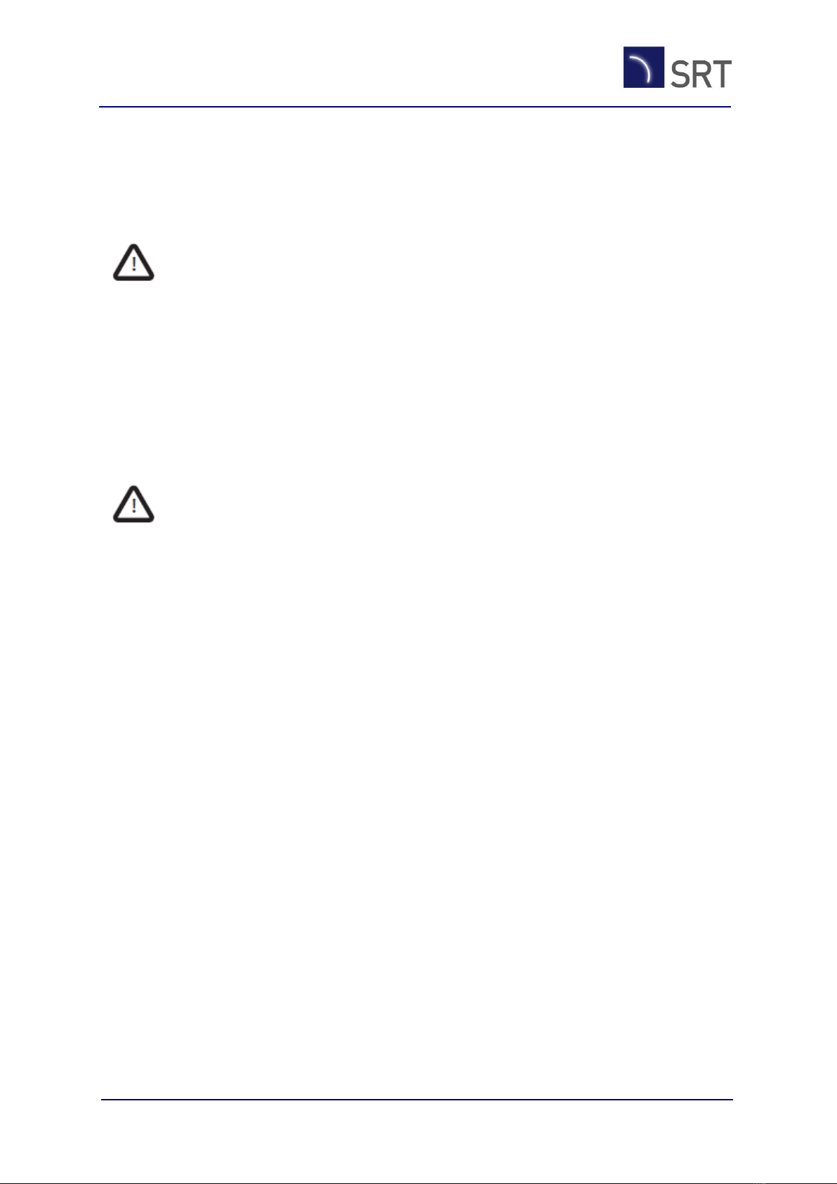
Trips
Messages
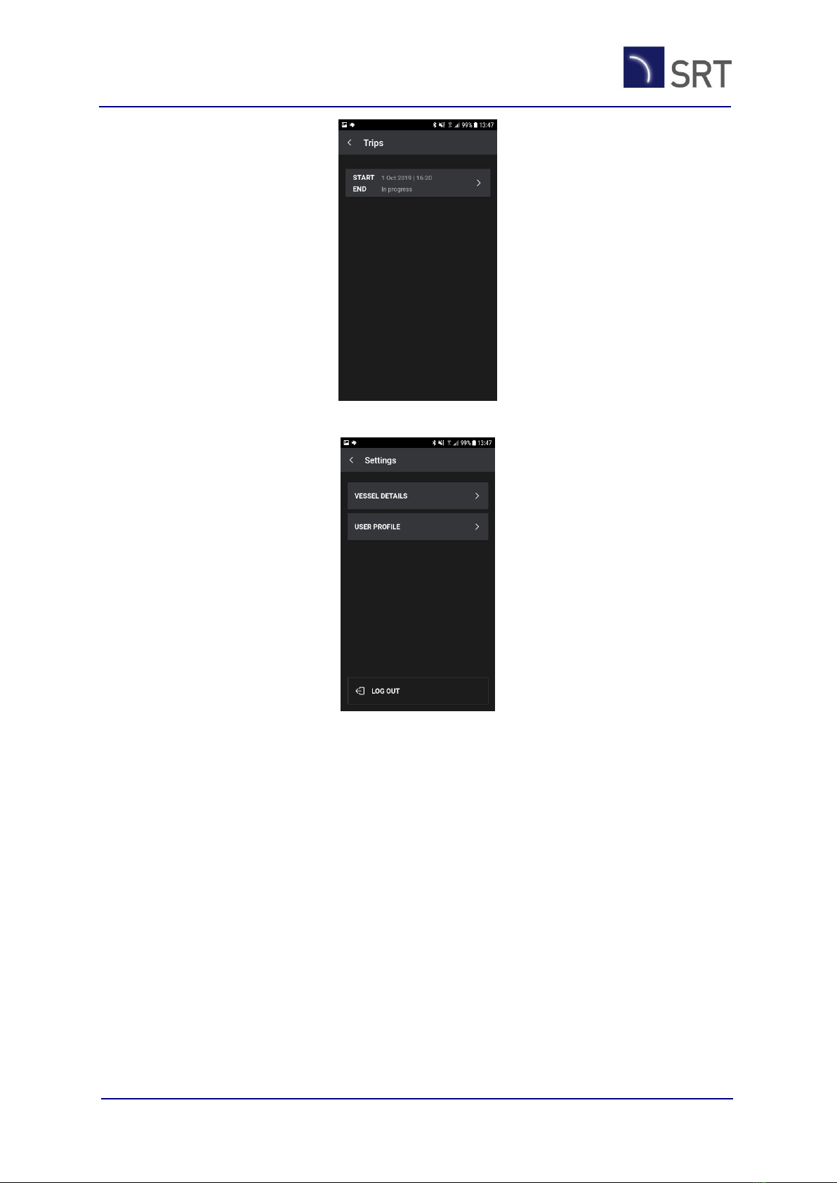
Settings

Document title: VMS-100 User Manual
Document number: VMSC-82
Company Confidential ©2019 SRT Marine Systems plc Page 17 of 21
The Messages menu allows for manual creation of a number of user triggered messages.
These could be required by a local authority. For example, a pre-departure message is
required when authorisation to leave port is required. This menu allows for creation of
these types of messages in addition to a general free-text message for non-specific
communication.
The Trips menu provides details of the current trip or historic trip data.
Document title: VMS-100 User Manual
Document number: VMSC-82
Company Confidential ©2019 SRT Marine Systems plc Page 18 of 21
The Settings menu shows the user and vessel information.
5.2 Basic+ Configuration
If the transceiver has been configured in the Basic+ configuration, an ERS1 device will be
provided as part of the product.
In this configuration, the ERS1 can be used to change the state of the transceiver from Port
to Transit to Fishing, rather than using the buttons on the top of the transceiver. Figure 3
shows how these state changes are displayed on the ERS1.

Document title: VMS-100 User Manual
Document number: VMSC-82
Company Confidential ©2019 SRT Marine Systems plc Page 19 of 21
Figure 3 –Basic+ ERS1 State Changes
The ERS1 can be used on the vessel during the fishing voyage, or for its main purpose in this
configuration which is to report the vessels catch.
The ERS1 provides a screen where the catch can be entered and declared as a Landing
Report. This can only be carried out when the vessel has returned to Port and the ERS1 has
detected a number of Fishing events (from the Fishing button).
When the Port button has been pressed for the final time to determine that the voyage is
complete, the system will require a Landing Report from the ERS1. This will be indicated on
the ERS1 screen as a red badge above the To-Do list on the ERS1.
When the Landing Report has been completed on the ERS1, the transceiver will officially
declare the vessel back in Port, the Port button will stop flashing, and the landing report will
be sent to the control centre.
The Port screen also shows an End Trip button which can be used to inform the control
centre that the current fishing trip is over.
Figure 4 shows example Landing Report screens.
Figure 4 - Landing Report

Document title: VMS-100 User Manual
Document number: VMSC-82
Company Confidential ©2019 SRT Marine Systems plc Page 20 of 21
5.3 Advanced Configuration
In this configuration, an ERS1 will be supplied with the product. This configuration tends to
be for larger vessels.
There are a number of operational differences in the way the ERS1 and transceiver work for
the advanced configuration and these are all controlled from the ERS1.
The ERS1 is essential for the vessel to operate in this configuration and the fishing voyage
will be severely compromised if the ERS1 is unavailable.
The states that the vessel can be in are increased for the advanced configuration. Using the
ERS1, the vessel can move from Port to Transit, but the Fishing state has been replaced by
two new states; Searching and Set/Catch. When actively searching for fish the Searching
mode should be selected from the ERS1 screen. From this screen the transceiver can return
to Transit or move into the Set/Catch state which acknowledges the act of fishing. All states
have the ability to return to the Transit state, and when each one exits an empty report will
be created in the ERS1 To-Do list. These reports must be filled in on the ERS1 prior to
returning to port, and they will be automatically transmitted to the control centre by the
transceiver.
Figure x shows how these state changes are carried out on the ERS1.
Advanced ERS1 State Changes
As with the Basic+ configuration, the ERS1 must create a landing record (or a number of
landing records) when the vessel is landing its catch back in Port.
In the advanced configuration, the ERS1 will also allow a Transhipment report to be created,
if a catch has been transferred to another vessel at sea.
The ERS1 also allows for the bunkering or crew change report to be created.
In the advanced configuration, the transition from Port to Transit and back again is carried
out automatically. It can be done using the ERS1 or buttons on the transceiver, but the
technology in the transceiver is intelligent enough to know when a port boundary has been
crossed.
Table of contents
Other SRT Transceiver manuals


