3
Siedle In-Home: Audio
„Single line“
Configuration
The In-Home bus: The Audio system
comprises a bus installation with a
two-core line permitting the
connection of up to 31 users, e.g.
bus telephones, door stations or
devices for switching and control
functions. Technically speaking, one
device can occupy more than one
user.
The line has its own bus line rectifier
for central functions such as speech,
door release or light switching. The
two cores assume the dual functions
of power supply and also
transmission of audio, switching and
control signals. Junction points and
branches are admissible at any
optional position in the line. In order
to connect more than 31 users,
several Siedle In-Home: Audio lines
can be interconnected.
Installation and programming
In their as-delivered status, the
devices are initially unprogrammed.
After the bus line rectifier is
switched on for the first time, each
of the connected devices is assigned
to a unique address on the line.
Once installation is complete, a
mutual "teach-in" process between
all the devices must be performed to
ensure that functions are correctly
executed (e.g. the bus telephone
rings as soon as the call button is
pressed).
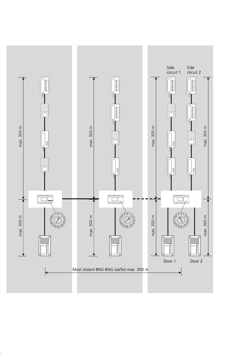
Siedle In-Home: Audio
„Multiple line“
Configuration
In-Home: Audio „Single line“ is
restricted to 31 users; In order to
connect more than 31 users, up to
15 lines can be coupled together.
Each line requires its own bus line
rectifier. Junction points and
branches are admissible at any
optional position in the line.
Installation and programming
To couple lines together, the bus line
rectifiers are linked by means of two
separate cores. Different addresses
must be set at the bus line rectifiers
using the “Adr.” rotary switch. The
bus supply unit accessory
ZBVG 650-... must be plugged into
one of the bus line rectifiers within
the system.
Then proceed using the same
method as for the In-Home: Audio
single line system.
Mounting, installation and
servicing work on electrical
devices may only be performed
by a suitably qualified electrician.
Failure to observe this regulation
could result in the risk of serious
damage to health or fatal injury
due to electric shocks.
• When working at the device,
observe the remarks relating to
mains cut-off.
• Observe the standard DIN EN
60065!
When establishing the electronic
connection, observe the
requirements of VDE 0805 /
EN 60950.
• The building installation must
include an all-pole mains switch with
a contact separation of at least
3 mm.
• Ensure that the connection point
in the building installation is fused
with max. 16 A.
• When planning large-scale
(complex) systems, the distributor
space required for the switch panel
mounting devices must be taken
into consideration in the distributor
planning process.
• No external voltages >30 V AC /
DC may be applied to bus users.
Devices with 230 V connection
In accordance with DIN VDE 0100
part 410, section 411.1.3 attention
must be paid to ensuring a safe
separation between bus lines and
the mains voltage; i.e. bus and
mains cores must not be permitted
to touch! The bus line cable (extra-
low safety voltage) must be stripped
back by the minimum possible.
1 In-Home bus: Audio
System description
2 Safety remarks
Danger