SST SST-ASI-SLC User manual

Scanner Quick Start
i
50 Northland Road
Waterloo, Ontario, CANADA
N2V 1N3
Tel: (519) 725-5136 Fax: (519) 725-1515
www.sstech.on.ca
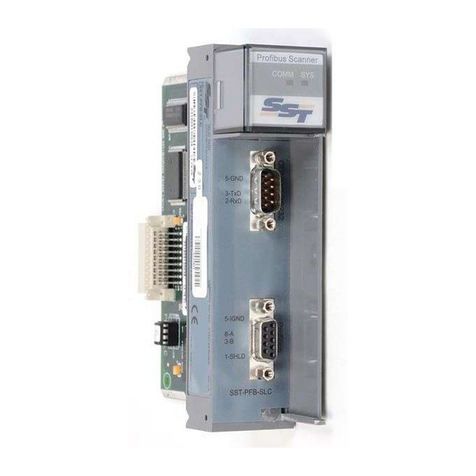
SST-ASI-SLC
User’s Guide
Version 1.30

SST-ASI-SLC User’s Guide
ii
Publication Revision: 1.30
Publication Date: November 3, 1999
This document applies to the SST-ASI-SLC scanner module.
Copyright © 1999 SST, a division of Woodhead Canada Limited
All rights reserved. No portion of the document may be reproduced in any
form without the prior written permission of Woodhead Canada Limited.
SST-ASI-SLC is a trademark of Woodhead Canada Limited. SST is a
trademark of Woodhead Industries, Inc. All other trade names are trademarks
or registered trademarks of their respective companies.
SST strives to ensure accuracy in our documentation. However, due to
rapidly evolving products, on occasion software or hardware changes may
not have been reflected in the documentation. If you notice any inaccuracies,
please contact SST.
Written and designed at SST, 50 Northland Road, Waterloo, Ontario, Canada
N2V 1N3.

iii
Preface .......................................................................... 1
1.1 Who should use this manual? ...................... 2
1.2 Purpose of this manual ................................. 2
1.3 Related Documentation ................................ 3
1.4 Conventions used in this manual .................. 4
1.5 Warranty ....................................................... 5
1.6 Technical Support ......................................... 6
Overview ....................................................................... 7
2.1 System Overview .......................................... 8
2.2 Hardware Features ....................................... 9
2.2.1 LEDs ................................................... 10
2.2.2 4-pin Phoenix Connectors ................... 10
2.2.3 Configuration Port ............................... 10
Scanner Quick Start .................................................... 11
3.1 Equipment and Tools .................................. 12
3.2 Procedures ................................................. 12
Contents
1
2
3

SST-ASI-SLC User’s Guide
iv
Theory of Operation ..................................................... 15
4.1 The AS-Interface ......................................... 16
4.2 Scanner Overview .......................................16
4.3 Configuring the AS-i Scanner ..................... 17
4.3.1 G File vs. Serial Port Configuration ..... 17
4.3.2 G File Configuration ............................ 17
4.3.3 Serial Port Configuration ..................... 18
4.3.4 Saving to EEPROM ............................. 18
4.4 Configuring Slaves ......................................18
4.4.1 Programming Slaves ...........................18
4.4.2 Replacing Slaves ................................19
4.4.3 Slave Parameters ................................19
4.5 LPS/LAS/LDS/SDL ..................................... 20
4.6 AS-i Modes .................................................21
4.6.1 Configuration Mode ............................. 21
4.6.2 Protected Mode ................................... 21
4.7 Powerup Sequence ..................................... 22
4.8 AS-i Faults .................................................. 22
4.9 Clearing Faults ............................................23
Installing and Wiring the Scanner Module ................... 25
5.1 Installing the Scanner Module .....................26
5.1.1 Removing the Scanner Module ........... 27
5.2 Wiring ..........................................................28
5.2.1 AS-i Wiring .......................................... 28
5.2.2 Serial Port Wiring ................................28
Configuring the Master and Slaves ............................. 29
6.1 Configuring the Scanner in APS ................. 30
6.2 Configuring the Scanner Using PLC-500
Ladder Logistics ...................................................31
6.3 Configuring the Scanner with RSLogix 500 32
6.4 Using Windows 95 Hyperterminal to Access
the Scanner via the Serial Port ............................33
6.5 Example of Slave Configuration .................. 34
6.6 Running the Scanner ..................................37
6.6.1 SLC Modes .........................................37
6.6.2 SLC Fault Codes ................................. 37
4
5
6

Contents
v
SLC File Reference ..................................................... 39
7.1 G File ..........................................................40
7.1.1 G File Examples .................................. 42
7.2 Input and Output Files ................................. 44
7.3 M0 and M1 Files ......................................... 46
7.3.1 Status Flag Bytes - Byte 1 (Low byte of
word 26) .............................................. 48
7.3.2 Status Flag Bytes - Byte 2 (High byte of
word 26) .............................................. 48
Upgrading the Scanner Firmware ................................ 49
8.1 LED Status and SLC Fault Codes .............. 51
Troubleshooting ........................................................... 51
9.1 AS-i Power Failure ......................................53
9.2 Slave Failure ............................................... 54
9.2.1 Single Slave Failure ............................54
9.2.2 Multiple Slave Failure ..........................54
9.3 An Important Note on AS-i Faults ............... 54
9.4 Other Troubleshooting Tips ........................55
9.4.1 Nothing shows up in a List Command . 55
9.4.2 Finding Failed Slaves .......................... 55
9.4.3 Unable to go Online ............................ 55
9.4.4 Unplugged Phoenix Connector ...........55
9.4.5 Scanner and Hand-held Programmers 55
9.4.6 Error Message: “Error during
transmission via AS-i bus” ...................56
9.4.7 Replaced Slave Didn’t Auto Address ..56
M0 and M1 Files .......................................................... 57
Specifications .............................................................. 61
7
8
B
A
9

1
Read this chapter to familiarize yourself with the rest of the manual. This
preface covers:
• who should use this manual
• the purpose of this manual
• related documentation
• conventions used in this manual
• warranty information
• obtaining technical support
1
Preface

SST-ASI-SLC User’s Guide
2
1.1 Who should use this manual?
Use this manual if you are responsible for designing, installing, programming
or troubleshooting control systems that use Allen-Bradley SLC processors
and the SST-ASI-SLC scanner.
You should have a basic understanding of SLC products and should
understand PLCs. Familiarity with AS-Interface (AS-i) modules and the AS-i
network is an asset.
Review The Getting Started Guide for APS, Allen-Bradley publication
1747-6.3, before using the APS software. Refer to your RS Logix 500
documentation for help on that software. For information on Ladder
Logistics, refer to your Ladder Logistics documentation.
1.2 Purpose of this manual
This manual explains how to install, configure, and operate the
SST-ASI-SLC scanner.

Preface
3
1.3 Related Documentation
For... Read this Document... Document
Number
An overview of SLC
products
SLC 500 System Overview A-B 1747-2.30
A description of how to
install and use the SLC 500
PLC
Installation and Operation
Manual for Modular Hardware
Style Programmable Controllers
A-B 1747-6.2
A procedural manual for
technical personnel who use
APS
Allen-Bradley Advanced
Programming Software (APS)
User Manual
A-B 1747-6.4
A reference manual for APS Allen-Bradley Advanced
Programming Software (APS)
Reference Manual
A-B 1747-6.11
An introduction to APS for
first time users
Getting Started Guide for APS A-B 1747-6.3
A training and quick
reference guide to APS
SLC 500 Software Programmer’s
Quick Reference Guide
A-B ABT-1747-
TSG001
An index of Allen-Bradley
publications
Allen-Bradley Publication Index A-B SD499
RSLogix information Getting Results with RSLogix 500 9399-RL50GR
Hardware Configuration
Reference Guide
9399-
HDWAREREF
RSLinx Lite User's Guide 9399-
WAB32LUG
AS-i information ASI: The Actuator-Sensor
Interface for Automation
Eds. Kriesel and Madelung
ISBN #
3-446-18265-9

SST-ASI-SLC User’s Guide
4
1.4 Conventions used in this manual
The following conventions are used throughout this manual:
• bulleted lists, such as this one, provide information, not procedural
steps
• numbered lists provide sequential steps
• italic type is used for command names
• courier font is used for text you should type
• hexadecimal numbers are shown with a trailing h. For example, 22h

Preface
5
1.5 Warranty
SST warrants all new products to be free of defects in material and
workmanship when applied in the manner for which they were intended and
according to SST’s published information on proper installation.
The Warranty period for the SST-ASI-SLC is one year from the date of
shipment.
SST will repair or replace, at its option, all products returned to it freight
prepaid, which prove upon examination to be within the Warranty definitions
and time period.
The Warranty does not cover costs of installation, removal or damage to
user’s property or any contingent expenses or consequential damages.
Maximum liability of SST is the cost of the product(s).
If it should be necessary to return or exchange items, please contact SST for a
Return Authorization number.
SST, a division of Woodhead Canada Limited
50 Northland Road
Waterloo, Ontario
N2V 1N3
CANADA
Voice: (519) 725-5136
Fax: (519) 725-1515
Email: [email protected]
Extended Warranty
24 month and 36 month extended warranties are available for an extra charge.
Contact SST for more information.

SST-ASI-SLC User’s Guide
6
1.6 Technical Support
Technical support is available during regular business hours by telephone, fax
or email from any SST office, or from the company Web site at
www.sstech.on.ca.
Documentation and software updates are available on our Web site.
North America
Telephone: 519-725-5136, Fax: 519-725-1515
Email: [email protected]
Europe
Telephone: +49/(0)7252/9496-30, Fax: +49/(0)7252/9496-39
Email: sst@woodhead.de
Asia
Telephone: +81-4-5224-3560, Fax: +81-4-5224-3561
Email: [email protected]

7
This chapter contains:
• a system overview
• information on hardware features
2
Overview

SST-ASI-SLC User’s Guide
8
2.1 System Overview
The SST-ASI-SLC is the AS-Interface (AS-i) scanner for the SLC 500. It
enables communication between an SLC processor (SLC 5/02 or later) and
AS-i modules on the AS-i network. The scanner supports 2 AS-i channels.
You can configure the AS-i network with the SLC G file or with the scanner’s
Config RS-232 port.
The scanner can occupy any slot in the local SLC chassis except slot 0, which
is reserved for the SLC processor. You can have multiple scanners in the
same rack.
The input and output data for the slaves is mapped into SLC I and O files. The
mapping of the I and O files is a fixed image of the network. SLC M0 and M1
files store network status information and the firmware version number.

Overview
9
2.2 Hardware Features
Front of AS-i Scanner
The following table describes the parts of the scanner. The side label of the
scanner provides module information.
Feature Description
COMM 1 and COMM 2 LEDs Display the communication status for each channel
FAULT LED Displays the fault status
4 pin Phoenix connectors
(AS-i Ch 1 and AS-i Ch 2)
Connections to AS-i networks
Config RS232 port For configuring I/O

SST-ASI-SLC User’s Guide
10
2.2.1 LEDs
There are 3 LEDs on the scanner, the FAULT LED and one COMM LED for
each AS-i network. Refer to section 9.1 for detailed information on what
these LEDs indicate.
When the SLC is in program mode, all the LEDs are off.
FAULT LED
The FAULT LED indicates the overall status of scanner operations.
At power up, the FAULT LED flashes for 2 seconds. While it flashes, you can
enter system configuration mode to download new firmware to the scanner.
Refer to chapter 8 for detailed information on how to update the scanner
firmware.
COMM LEDs
The COMM LED for each channel displays the status of that channel.
If there are no network errors and the SLC is in run mode, the COMM LEDs
are green.
2.2.2 4-pin Phoenix Connectors
Each 4-pin Phoenix Combicon connector allows you to connect the scanner
to one AS-i network. Each 4-pin connector consists of 2 sets of 2 pins for user
convenience. Pin 1 and pin 3 are internally connected, as are pins 2 and 4.
You can connect AS-i power to one set of pins and the AS-i network to the
other.
2.2.3 Configuration Port
The configuration port is a standard RS-232, DB9 style connector. It is used
for field upgrades of module firmware and for configuration of AS-i slave
addresses and information.

11
This chapter provides all the necessary information to get you up and
running quickly. It:
• tells you what tools and equipment you need
• describes how to configure and program the scanner module
• explains how to install the scanner module
• discusses system power-up procedures
Detailed explanations about the procedures listed are not included in this
quick start guide. References are provided to additional information in later
chapters. If you have any questions or are unfamiliar with the terms used or
concepts presented, read the referenced chapters and other documentation
before you proceed.
3
Scanner Quick Start

SST-ASI-SLC User’s Guide
12
3.1 Equipment and Tools
Have the following tools and equipment ready:
• SLC programming equipment
• terminal emulation software
• null modem cable, 9-pin female to female (provided by SST)
• AS-i cable to connect the scanner to the AS-i network
• AS-i power supply
3.2 Procedures
1. Unpack the module. Make sure you received the AS-i scanner and a
serial null modem cable for configuring I/O.
2. Review the power requirements of your system to verify that your
chassis supports placement of the scanner module. The scanner
consumes 500 mA at 5 VDC.
Calculate the total load on the system power supply using the
procedure described in the SLC 500 Modular Style Installation &
Operation Manual, Allen-Bradley Publication 1747-6.2 or the SLC
500 Family System Overview, Publication 1747-2.30.
3. Make sure system power is off. Insert the scanner module into your
1746 chassis. Connect AS-i power to the scanner. The slaves require
AS-i power to be able to communicate with the scanner.
Refer to chapter 5 in this guide if you need help installing or wiring
the module.
4. Set up your system I/O configuration for the particular slot where
you installed the scanner. Using APS or RSLogix 500 software,
configure the scanner as Other and enter the scanner module ID
(13635).
Refer to chapter 6 for details on configuring the scanner with several
popular programming packages. RSLogix 500 users should refer to
section 6.3 for important information on dealing with a G file
problem in RSLogix.
5. Set the M1 and M0 file sizes to 40 words.
6. Set scanned inputs and outputs to 32 words.
7. Set the G file size to 64 words.

Scanner Quick Start
13
8. Modify the G file.
For details on the G file layout and how to configure the G file, refer
to section 7.1.
For this quick start, set the following words:
Word 1 - 8000h
Word 63 - 3543h (13635 decimal) (scanner module ID)
All other words can be set to 0000h.
Once you verify your system is operating correctly, you can
configure the rest of the network in the G file.
9. Use the provided serial cable to connect the scanner to your
configuration computer via the Config RS232 port.
10. Run your terminal emulation software. Set the baud rate to 38400
and the parameters to No parity, 8 data bits and one Stop bit. Press
the [*] key to get the scanner’s attention. Choose the network to
configure.
11. Hook up AS-i power and add an AS-i slave.
12. In your terminal software, perform a List command and verify the
slave appears on the network.
If the slave is listed at address 0, use the Address command to
change it to the desired address. Refer to section 6.5 for an example
of configuring a slave.
Continue adding slaves and setting their addresses.
13. Save the configuration and exit Config mode.
14. Put the SLC in run mode. This starts the scanner module scanning
I/O. Verify that you can read inputs and write outputs.

SST-ASI-SLC User’s Guide
14
Table of contents
Other SST Scanner manuals

