SST SST-PFB-SLC User manual

i
50 Northland Road
Waterloo, Ontario, CANADA
N2V 1N3
Tel: (519) 725-5136 Fax: (519) 725-1515
www.sstech.on.ca
SST-PFB-SLC
User’s Guide
Version 2.04

SST-PFB-SLC User’s Guide
ii
Publication Revision: 2.04
Publication Date: October 11, 2000
This document applies to the SST-PFB-SLC ProfiBus Scanner.
Copyright © 2000 SST, a division of Woodhead Canada Limited
All rights reserved. No portion of this document may be reproduced in any
form without the prior written permission ofWoodhead Canada Limited.
Siemens is a trademark of Siemens AG. PLC, SLC and APS are registered
trademarks of Allen-Bradley. RS Logix 500 and PLC-500 Ladder Logistics
are trademarks of Rockwell Software. All other trade names referenced are
trademarks or registered trademarks of their respective companies.
SST strives to ensure accuracy in our documentation. However, due to
rapidly evolving products, on occasion software or hardware changes may
not have been reflected in the documentation. If you notice any inaccuracies,
please contact SST.
Written and designed at SST, 50 Northland Road,Waterloo, Ontario, Canada
N2V 1N3.

iii
Introduction ....................................................................1
1.1 Purpose of this manual .................................2
1.2 Related Documentation ................................2
1.3 Conventions used in this manual ..................3
1.3.1 Special Notation ....................................3
1.4 Warranty .......................................................4
1.5 Technical Support .........................................5
1.5.1 Before you call for help .........................5
1.5.2 Getting help ...........................................5
Overview .......................................................................7
2.1 System Overview ..........................................8
2.2 Hardware Features .....................................10
2.2.1 LEDs ...................................................11
2.2.2 9-pin ProfiBus connector .....................11
2.2.3 Configuration port ...............................11
Contents
1
2

SST-PFB-SLC User’s Guide
iv
Quick Start ...................................................................13
3.1 Equipment and tools ...................................14
3.2 Package Contents .......................................14
3.3 Power Requirements ..................................15
3.4 Procedures ..................................................16
3.4.1 Setting up the Scanner ........................16
3.4.2 Getting the Scanner Running ..............17
Installation and Wiring .................................................19
4.1 Installing the Scanner Module .....................20
4.1.1 Installation ...........................................21
4.1.2 Removal ..............................................21
4.2 Wiring ..........................................................22
4.2.1 ProfiBus Wiring ...................................22
4.2.2 Serial Port Wiring ................................23
4.3 Status LEDs ................................................24
4.3.1 SYS LED .............................................24
4.3.2 COMM LED .........................................25
DP Master Configuration and Programming ................27
5.1 Configuring the Scanner .............................28
5.1.1 APS .....................................................28
5.1.2 PLC-500 Ladder Logistics ...................29
5.1.3 RS Logix 500 .......................................30
5.2 Creating an I/O Configuration in the SST
ProfiBus Configuration Tool .................................31
5.3 Creating an I/O Configuration in COM
PROFIBUS. ..........................................................33
5.3.1 Mapping the Addresses ......................35
5.4 Uploading the I/O Configuration to the
Scanner ................................................................37
5.4.1 Network Parameter Errors ..................40
5.4.2 Binary File Configuration Errors ..........40
5.4.3 Flash Programming Errors ..................41
5.4.4 COM PROFIBUS Address Assignment
Errors ..................................................41
5.4.5 Fatal Errors .........................................42
5.5 Running the Scanner ..................................43
5.6 Using the Watch-Dog Timer .......................44
5.6.1 How the Host Watch Dog works .........44
4
3
5

Contents
v
DP Master Application Examples ................................45
6.1 Addressing ..................................................46
6.2 32 Discrete Output Module .........................46
6.3 32 Discrete Input Module ............................47
6.4 Example: M0/M1 Addressing ......................47
6.5 Example: Accessing Data ...........................47
6.6 Example: Using Flex I/O .............................50
Using the Scanner Module as a DP Slave ..................53
7.1 Slave Received Data ..................................54
7.2 Slave Transmit Data ...................................55
7.3 Displaying the DP Slave Configuration .......56
7.4 Disabling DP Slave Operation ....................56
7.5 Using the Module Only as a DP Slave ........56
7.5.1 Local Station .......................................57
7.5.2 Active/Passive .....................................57
7.5.3 Baud Rate ...........................................57
7.5.4 Other Network Options ........................57
7.5.5 Displaying Network Settings ...............57
7.6 Configuring the Module as a Slave Using
COM Profibus ......................................................57
Using FDL ....................................................................59
8.1 FDL (Layer 2) Messaging ...........................60
8.1.1 Input Table I:31 ...................................60
8.2 FDL Messages ............................................62
8.3 FDL SAPs ...................................................69
8.3.1 SAP Receive Buffers ...........................70
8.3.2 SAP Transmit Buffers ..........................71
8.3.3 Receiving Broadcast/Multicast
Messages ............................................71
8.4 FDL Diagnostic Counters ............................74
8.5 FDL Network Parameters ...........................75
8
7
6

SST-PFB-SLC User’s Guide
vi
Diagnostics ..................................................................79
9.1 Status Register ...........................................80
9.2 Scanner Firmware Version Number ............80
9.3 DP Master Slave Status Table ....................81
9.4 DP Master Slave Error Table ......................82
9.5 DP Master Slave Extended Status Table ....82
9.5.1 Reading the Extended Status .............83
9.6 DP Master Error Information Table .............83
9.7 DP Slave Status Register ...........................87
9.8 DP Slave Error Register ..............................88
9.9 Diagnostic Counters ....................................89
9.9.1 General Statistics ................................91
9.9.2 DP Master Statistics ............................91
9.9.3 DP Slave Statistics ..............................92
9.9.4 ASPC2 PROFIBUS Controller
Statistics ..............................................92
9.10 Summary of Diagnostic Locations ..............94
9.10.1 M1 File ................................................94
9.10.2 M0 File ................................................94
Upgrading the Scanner Firmware ................................95
Network Parameter Defaults .......................................97
M0 and M1 Files ........................................................101
12. Addressing M0 and M1 Files ....................103
1.2.1 Restrictions on Using M0-M1 Data
File Addresses ..................................103
1.2.2 Monitoring Bit Addresses ..................104
1.2.3 Transferring Data between Processor
Files and M0/M1 Files .......................104
11
10
9
12

Contents
vii
Technical Data ...........................................................105
Index ..........................................................................107
A

SST-PFB-SLC User’s Guide
viii

1
1
Introduction
Revision Notes and Exceptions
This chapter describes:
• the purpose of this manual
• related documentation
• style conventions used in this manual
• warranty and technical support information
As of Publication Date Exception Note

SST-PFB-SLC User’s Guide
2
1.1 Purpose of this manual
This manual explains how to install and use the SST-PFB-SLC scanner. It
describes the procedures you use to install, configure, and operate the
SST-PFB-SLC scanner.
1.2 Related Documentation
For information on ProfiBus, refer to one of the following:
• ProfiBus standard DIN 19 245 parts 1 and 3. Part1 describes the low
level protocol and electrical characteristics. Part 3 describes the DP
protocol.
• European standard EN 50170
• ET 200 Distributed I/O System Manual, 6ES5 998-3ES22
• IEEE 518 Guide for the Installation of Electrical Equipment to
Minimize Electrical Noise Input to Controllers
For... Read this Document... A-B
Document
Number
An overview of SLC products SLC 500 System Overview 1747-2.30
A description of how to install
and use the SLC 500 PLC Installation and Operation
Manual for Modular Hardware
Style Programmable Controllers
1747-6.2
A procedural manual for
technical personnel who use
APS
Allen-Bradley Advanced
Programming Software (APS)
User Manual
1747-6.4
A reference manual for APS Allen-Bradley Advanced
Programming Software (APS)
Reference Manual
1747-6.11
An introduction to APS for first
time users Getting Started Guide for APS 1747-6.3
A training and quick reference
guide to APS SLC 500 Software
Programmer’s Quick Reference
Guide
ABT-1747-T
SG001
An index of Allen-Bradley
publications Allen-Bradley Publication index SD499

Introduction
3
1.3 Conventions used in this manual
The following conventions are used throughout the manual:
• Listed items, where order is of no significance, are preceded by
bullets.
• Listed items, to be performed in the order in which they appear, are
preceded by a number.
• References to commands, or dialog boxes areitalicized.
• User entry text is in Courier 9 pt font
• Buttons that the user may press are in SMALL CAPS.
1.3.1 Special Notation
The following special notations are used throughout the manual:
Warning messages alert the reader to situations where
personal injury may result. Warnings are accompanied by the
symbol shown, and precede the topic to which they refer.
Caution messages alert the reader to situations where
equipment damage may result. Cautions are accompanied by
the symbol shown, and precede the topic to which they refer.
A note provides additional information, emphasizes a point,
or gives a tip for easier operation. Notes are accompanied by
the symbol shown, and follow the text to which they refer.

SST-PFB-SLC User’s Guide
4
1.4 Warranty
ST guarantees that all new products are free of defects in material and
workmanship when applied in the manner for which they were intended and
according to SST’s published information on proper installation. The
Warranty period for the SST-PFB-SLC is 1 year from the date of shipment.
SST will repair or replace, at our option, all products returned freight prepaid,
which prove upon examination to be within the Warranty definitions and time
period.
The Warranty does not cover costs of installation, removal or damage to user
property or any contingent expenses or consequential damages. Maximum
liability of SST is the cost of the product(s).
Product Returns
If it should be necessary to return or exchange items, please contact SST for a
Return Authorization number.
SST
50 Northland Road
Waterloo, Ontario, N2V 1N3
Voice: (519) 725-5136
Fax: (519) 725-1515

SST-PFB-SLC User’s Guide
5
1.5 Technical Support
1.5.1 Before you call for help
Before calling for technical support, ensure that you have the following
information readily available:
• SLC module name and serial number
• module revision and series, firmware revision, other modules
installed
• operating system type and version
• details of the problem - application module type and version, target
network, circumstances that caused the problem
1.5.2 Getting help
For questions or problems that the manual does not address, contact Profibus
Technical Support by mail, fax or email, or by phone during regular business
hours (Eastern Standard Time).
Profibus Technical Support
SST
50 Northland Road
Waterloo, Ontario
N2V 1N3
CANADA
Voice: (519) 725-5136
Fax: (519) 725-1515
Email: techsupport@sstech.on.ca
Web site: www.sstech.on.ca
Documentation and software updates are available on ourWeb site.

SST-PFB-SLC User’s Guide
6

7
2
Overview
This chapter describes the following:
• system overview
• how the scanner interacts with the SLC processor
• how the scanner interacts with ProfiBus DP I/O modules

SST-PFB-SLC User’s Guide
8
2.1 System Overview
The SST-PFB-SLC is the ProfiBus scanner for the SLC 500. It enables
communication between a SLC processor (SLC 5/03 or later) and DP remote
I/O devices on a ProfiBus network. It acts as a ProfiBus DP remote I/O
scanner to scan up to 96 slaves. The scanner supports up to 244 bytes of input
data and 244 bytes of output data per slave.
If you use the SST ProfiBus Configuration Tool to configure the scanner, you
can have up to 1000 words of input data and 1000 words of output data.
If you use Siemens COM PROFIBUS to configure the scanner, it supports up
to 160 words of input data and 160 words of output datain total.
The scanner can reside in any slot in the local SLC chassis except slot 0
(reserved for the SLC processor). You can havemultiple scanners in the same
rack.
The scanner supports all standard ProfiBus baud rates (9600, 19200, 93.75k,
187.5k, 500k, 750k, 1.5M, 3M, 6M, 12M)
You configure the I/O on the DP network using either the SST ProfiBus
Configuration Tool or Siemens COM PROFIBUS configuration software.
The SST configuration tool exports the configuration to a*.bss file (binary),
while COM PROFIBUS exports the configuration to a *.2bf file (binary).
You upload the configuration to the scanner via the serial port on the scanner,
using an Xmodem transfer from any serial communications software.
The scanner stores this configuration in flash memory on the scanner so you
don’t need to upload the configuration every time you start the SLC.
The input and output data for the slaves is mapped into SLC I, O, M0 and M1
files. The mapping depends on the addresses you assign in the configuration
you create with either configuration tool.
The scanner does not require setting up a G file in the SLC. All the
configuration is done with the SST configuration tool or COM PROFIBUS.
The scanner maintains the following status information about the network
and the I/O modules on the network:
• slave status for each slave
• network diagnostic counters
• DP master diagnostic counters
• FDL diagnostic counters

Overview
9
The SLC processor scan and the scanner I/O scan are independent
(asynchronous) of each other.
The SLC processor reads the scanner input data during its input scan and
writes the output data during its output scan. The scanner continues reading
input data from the slaves and writing output data to the slaves independent of
what the SLC is doing.
The scanner module can also act as a DP slave to another DP master on the
same network. It supports up to 122 words of input data and 122 words of
output data as a slave. Up to 32 words of data can be configured to be in the
input and output files. With the SST ProfiBus Configuration Tool, up to 1000
words of data can be configured in the M0 and M1 files. With COM
PROFIBUS, up to 122 words of data can be configured in the M0 and M1
files.
The scanner supports up to four FDL SAPs and up to four FDL message
blocks.
Caution
this equipment is neither designed for, nor intended for use in
installations where it is subject to hazardous voltages and
hazardous currents.

SST-PFB-SLC User’s Guide
10
2.2 Hardware Features
The scanner's features are shown here. LED information is in section 4.3.
Feature Description
status LEDs display the communication and system status
front label identifies the scanner
9-pin ProfiBus connector for connection to the ProfiBus network
self locking tabs secure the scanner in the chassis slot
side label (nameplate) provides module information
configuration port for uploading I/O configuration data

Overview
11
2.2.1 LEDs
There are two LEDs on the scanner, the SYS LED and the COMM LED.
The SYS LED indicates overall status of scanner operations.
The COMM LED indicates communication status.
Refer to section 4.3, Status LEDs, in this manual for more detailed
information.
2.2.2 9-pin ProfiBus connector
The 9-pin ProfiBus connector connects the scanner to the ProfiBus network.
2.2.3 Configuration port
Use the configuration port to upload I/O configurationsexported from the
SST ProfiBus Configuration Tool or Siemens COM PROFIBUS to the
scanner.

SST-PFB-SLC User’s Guide
12
Table of contents
Other SST Scanner manuals
Popular Scanner manuals by other brands

Plustek
Plustek SecureScan X50 user guide

Creo
Creo iqsmar series Installation and maintenance guide
AGFA
AGFA DuoScan HiD owner's guide

Wenglor
Wenglor BLN0x1R10 operating instructions
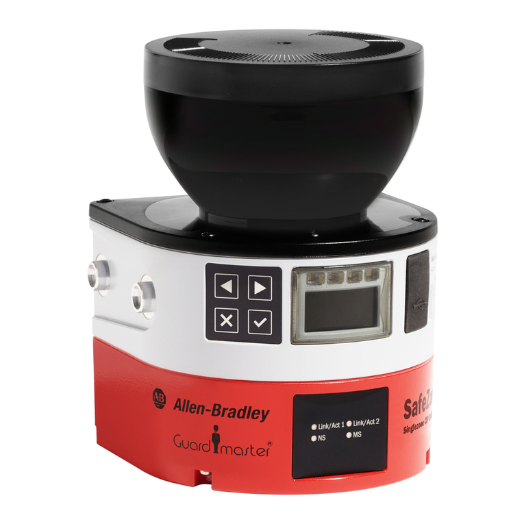
Allen-Bradley
Allen-Bradley Guardmaster SafeZone 3 installation instructions
Canon
Canon Colortrac imagePROGRAF MFP Z36 Service Support Guide

