SSV MLS/160A User guide
MLS/160A
Soft Sensor
System Reference
SSV Software Systems GmbH
Dünenweg 5
D-30419 Hannover
Phone: +49 (0)511/40 000-0
Fax: +49 (0)511/40 000-40
Document Revision: 1.1
Date: 2020-11-18

MLS/160A – System Reference
2
D oc u m e n t R e v i s i o n 1 . 1
CONTENT
1
INTRODUCTION ............................................................................................................... 3
1.1
Safety Guidelines ................................................................................................................... 3
1.2
Conventions .......................................................................................................................... 3
1.3
Block Diagram ....................................................................................................................... 4
1.4
Nameplate ............................................................................................................................. 4
1.
Features and Technical Data .................................................................................................
2
OVERVIEW ....................................................................................................................... 6
3
INTER ACES ................................................................................................................... 7
3.1
JTAG/Debug – J1.................................................................................................................... 7
3.2
Primary RS48 Screw Terminal – J2 ...................................................................................... 8
3.3
Power Connector – J4 ........................................................................................................... 8
3.4
Power/Status LED – D1 ......................................................................................................... 8
4
OPERATING SYSTEM ..................................................................................................... 9
4.1
A/B Boot Concept ................................................................................................................ 10
4.2
Secure Device Update (SDU) ............................................................................................... 11
5
PROTOCOL SPECI ICATION........................................................................................ 12
.1
Interface .............................................................................................................................. 12
.2
Operating states .................................................................................................................. 12
.3
Datagrams ........................................................................................................................... 13
6
MECHANICAL DIMENSIONS ......................................................................................... 19
7
CONNECTING TO AN RMG/941 .................................................................................... 20
8
HELP UL LITERATURE ................................................................................................ 21
CONTACT ............................................................................................................................. 21
DOCUMENT HISTORY ......................................................................................................... 21

MLS/160A – System Reference
D o c u m e n t R e v i s i o n 1 . 1
3
1 INTRODUCTION
This document describes the basic hardware and software components of the soft sensor
MLS/160A.
1.1 Safety Guidelines
Please read the following safety guidelines carefully! In case of property or personal
damage by not paying attention to this document and/or by incorrect handling, we do
not assume liability. In such cases any warranty claim expires.
ATTE TIO !
Observe precautions for handling – electrostatic sensitive device!
• Please pay attention that the power cord or other cables are not s ueezed or dam-
aged in any way when you set up the device.
• Do NOT turn on the power supply while connecting any cables, especially the pow-
er cables. This could cause damaged device components! First connect the cables
and THEN turn the power supply on.
• The installation of the device should be done only by ualified personnel.
• Discharge yourself electrostatic before you work with the device, e.g. by touching a
heater of metal, to avoid damages.
• Stay grounded while working with the device to avoid damage through electrostat-
ic discharge.
• The case of the device should be opened only by ualified personnel.
1.2 Conventions
Convention
Usage
bold
Important terms
monospace
Pathnames, internet addresses and program code
Table 1: Conventions used in this document

MLS/160A – System Reference
4
D o c u m e n t R e v i s i o n 1 . 1
1.3 Block Diagram
Figure 1: Block diagram MLS/160A
1.4 Nameplate
Figure 2: ameplate MLS/160A
MLS/160A – System Reference
D o c u m e n t R e v i s i o n 1 . 1
5
1. Features and Technical Data
Processor
Manufacturer/Type
STM32 micro controller
with ARM 32
-
bit Cortex
-
M3 Core
Clock speed
max. 72
MHz
Memory
RAM
20
KB SRAM
Flash
64
KB
Interfaces
Serial I/Os
1x RS485 half duplex, 115200
bps
JTAG/Debug
1x 18
-
pin connector (internal)
Inertial Measurement Unit osch MI160
3
-
Axis Acceler
ometer
max. sampling rate: 1600
Hz
max. analog band width:
684 Hz for x- and y-axis; 353 Hz for z-axis
Range: ±2 g (g = 9.81 m/s²)
Resolution: signed 16-bit integer
3
-
Axis Gyroscope
max. sampling rate: 1600
Hz
max. analog band width: 523.9 Hz
Range: ±2000°/s
Resolution: signed 16-bit integer
Environmental Sensor osch ME280
Humidity
Operating range 0 .. 100% rel. humidity
Pressure
Operating range 300 .. 1100
hPa
Temperature
Operating range
-
40 ..
85
°C
Software
Operating system
RIOT
2019.04
Protocol
s
RS48
5
to t
ransfer
the
measurement data
in a special
Data
Streaming Mode
Configuration
Via Datagram
s
Miscellaneous
Firmware upgrade via Secure Device Update app (A/B boot)
Displays/Control Elements
LEDs
1x Power/status
Electr
ical Characteristics
Power sup
ply
12 .. 24
VDC from external power supply
Current consumption
typ. 20
mA @12
V / typ. 10
mA @24
V
Mechanical Characteristics
Protection class
IP40/IP65
Mass
<
5
0
g
Dimensions
91.2
mm x 43.2
mm x 26
mm (without cable)
Operating temperature
-
2
0 ..
7
0
°C
Standards and Certifications
EMC
CE
Environmental
standards
RoHS, WEEE
Table 2: Features MLS/160A
MLS/160A – System Reference
6
D o c u m e n t R e v i s i o n 1 . 1
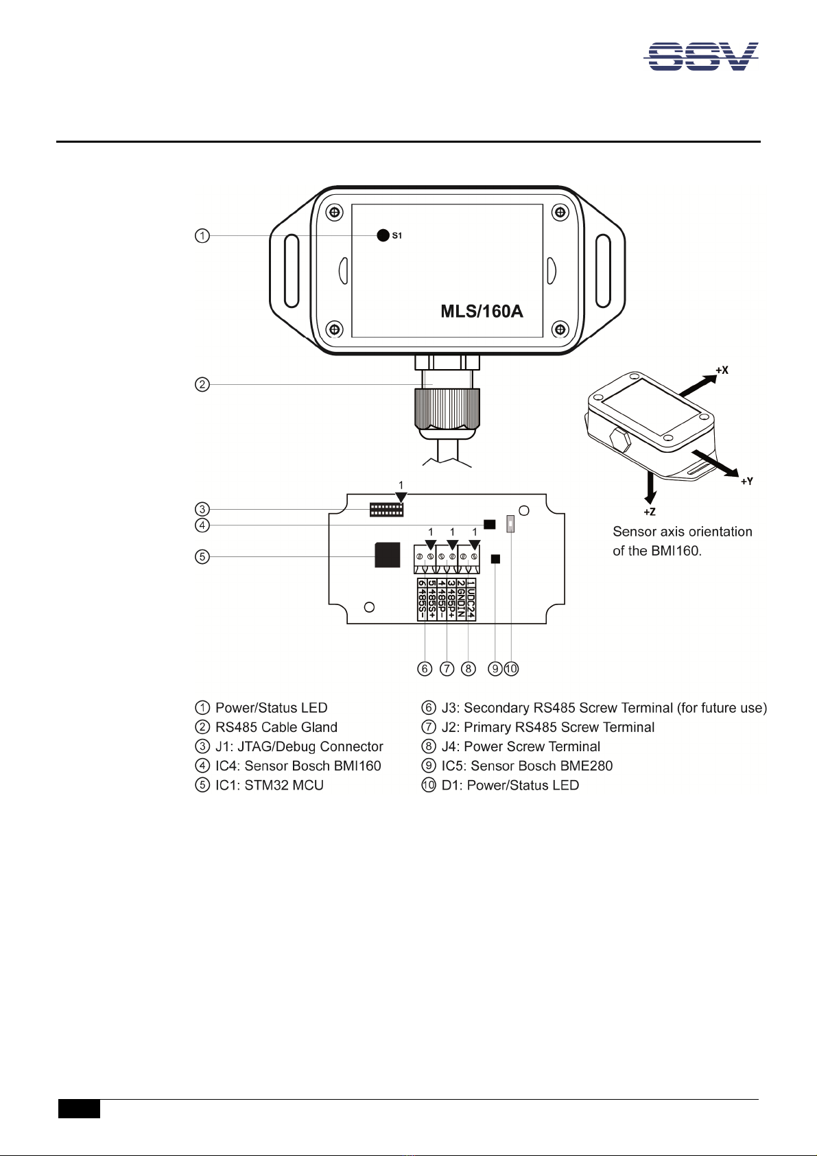
2 OVERVIEW
Figure 3: Overview MLS/160A
MLS/160A – System Reference
D o c u m e n t R e v i s i o n 1 . 1
7
3 INTERFACES
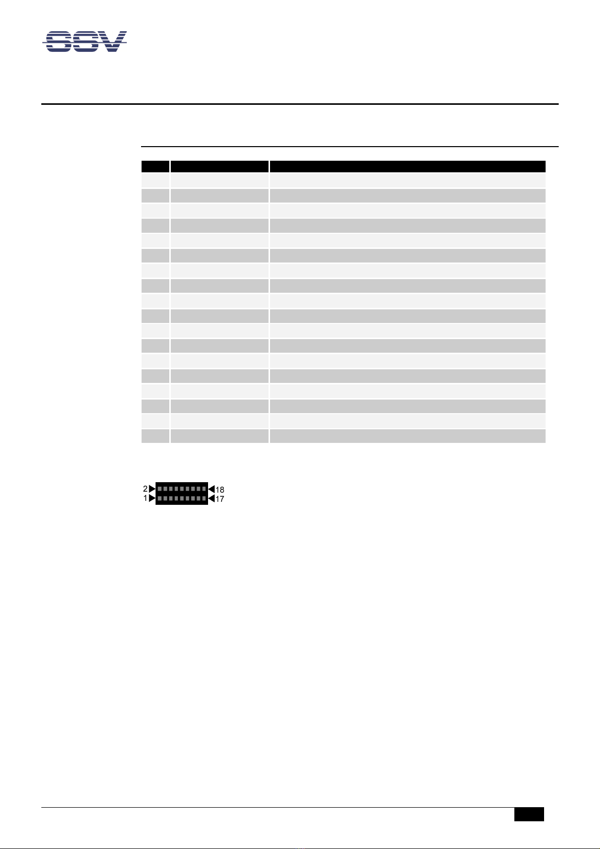
3.1 JTAG/Debug – J1
Pin
Name
Func
tion
1
VCC3
3.3 VDC
2
G D
Ground
3
TRST#
Test Reset
4
BOOT0
Boot0 Pin (please refer to STM32 datasheet)
5
TDI
Test Data In
6
TXD
1
Debug Port TXD
1
Pin
7
TMS
Test Mode Select
8
RXD
1
Debug Port RXD
1
Pin
9
TCK
Test Clock
10
G D
Ground
11
---
Reserv
ed. Do not use.
12
---
Reserved. Do not use.
13
TDO
Test Data Out
14
---
Reserved. Do not use.
15
RESET#
Reset
16
---
Reserved. Do not use.
17
G D
Ground
18
---
Reserved. Do not use.
Table 3: Pinout JTAG/Debug connector
MLS/160A – System Reference
8
D o c u m e n t R e v i s i o n 1 . 1
3.2 Primary RS48 Screw Terminal – J2
Pin
Name
Function
Wire color
3
RS485P+
COM2 Serial Port:
primary
RS485 RX /TX+
Green
4
RS485P
-
COM2 Serial Port:
primary RS485 RX /TX
-
Yellow
Table 4: Pinout primary RS485 screw terminal
3.3 Power Connector – J4
Pin
Name
Function
Wire color
1
VCC24
12
..
24
Volt
power input
White
2
G D
Ground
Brown
Table 5: Pinout power connector
CAUTIO !
Providing the MLS/160A with a higher voltage than the regular 12 .. 24 VDC ±10% could
cause damaged device components!
Do OT turn on the power supply while connecting any cables, especially the power ca-
bles. This could cause damaged device components! First connect the (power) cables and
THE turn the power supply on.
3.4 Power/Status LED – D1
Table 10 shows the two modes of the LED D1 on the MLS/160A’s front.
Mode
Function
On
O.K./Sampling
Blink
Waiting on
c
onfiguration/IDLE
Table 6: LED D1 modes
MLS/160A – System Reference
D o c u m e n t R e v i s i o n 1 . 1
9
4 OPERATING SYSTEM
The MLS/160A’s firmware is built with the lightweight real time operating system RIOT.
RIOT is a free, open source operating system and is designed for the particular re uire-
ments of Internet of Things (IoT) scenarios. For more information please see:
https://riot-os.org/
RIOT offers a low memory footprint, high energy efficiency, real-time capabilities and a
modular and configurable communication stack. It provides a microkernel, utilities like
cryptographic libraries, data structures (bloom filters, hash tables, priority ueues), a shell,
various network stacks, and support for various microcontrollers, radio drivers, sensors,
and configurations for entire platforms, e.g. the STM32 MCU family.
The microkernel itself comprises thread management, a priority-based scheduler, a power-
ful API for inter-process communication (IPC), a system timer, and mutexes.
All this makes it an ideal OS for the MLS/160A and opens up versatile options for own de-
velopments, as well as benefiting from community driven enhancements.
In order to build an application or library with RIOT, you first need to download the source
code. You can obtain the latest firmware code from the SSV Github account:
https://github.com/SSV-embedded/fw-mls160a
To compile RIOT for the MLS/160A, you need to install the corresponding toolchain for
STM32 MCUs (ARM 32-bit Cortex-M3).
On a Linux host you may use the default GNU cross compiler for ARM architecture of your
Linux distribution. Please refer to the RIOT webpage to see how to set up a cross compiler
environment for a different operating system like Windows10.
Table 7 shows the STM32 GPIO mapping of the MLS/160A:
RIOT OS
STM32
GPIO line in use
MLS/160A
I2C
I2C1
PB6/7
BMI160/BME280
UART0
USART1
PA9/10
Debug Connector
UART1
USART2
PA2/3
J2 RS458P
Direction1
PortA1
PA1
IC2 RS485 Transceiver
UART2
USART3
PB10/11
J3 RS458S
Direction2
PortB14
PB14
IC3 RS485 Transceiver
LED0
PortC13
PC13
Power/Status
LED
Table 7: STM32 GPIO mapping of MLS/160A
MLS/160A – System Reference
10
D o c u m e n t R e v i s i o n 1 . 1
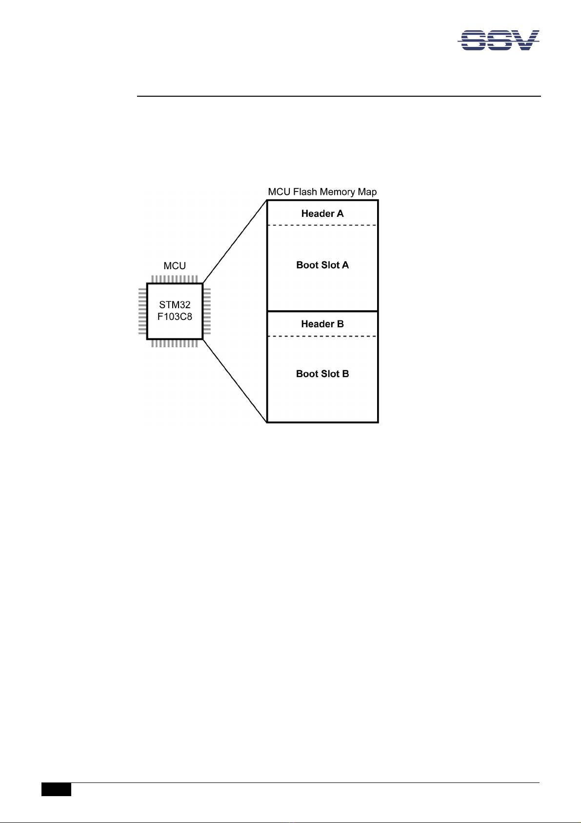
4.1 A/B Boot Concept
The MLS/160A has an A/B boot concept is based on the RIOTBOOT bootloader. It enables,
for instance, the Secure Device Update (SDU) function (please see chapter 4.2).
The Flash memory of the STM32 MCU is divided in two so-called boot slots ("A" and "B")
like shown in figure 4. Each of them may store the MLS/160A’s firmware.
Figure 4: Division of the MCU Flash memory
Header
Each boot slot has a header containing following information as 32-bit unsigned integer
(uint32):
• magic_number: header magic number ("RIOT")
• version: partition/boot slot version
• start_addr: memory address after the allocated space
• chksum: checksum of the header
Boot Process
First the boot loader checks the header checksum of each slot.
If both slots have a valid checksum, the boot loader uses the slot with the higher version
number to continue the boot process.

MLS/160A – System Reference
D o c u m e n t R e v i s i o n 1 . 1
11
4.2 Secure Device Update (SDU)
The secure device update function allows the secure remote update of the MLS/160A’s
firmware. Therefore it uses the A/B boot concept (please see chapter 4.1).
To run a secure device update the SDU app must be installed on the remote station, e.g.
the remote maintenance gateway RMG/941. The SDU app contains an SDU agent, which
connects with the SDU device driver of the MLS/160A.
Figure 5: Diagram of the Secure Device Update
Update Process
The update process follows these steps:
• Invalidating the inactive slot by setting its magic number from "RIOT" to "0000".
• Writing the new header and firmware excluding the magic number into the inactive
slot. The slot remains invalid because its magic number is still "0000".
• Verifying the written slot by an SHA256 HMAC (Keyed-Hash Message Authentica-
tion Code).
If the HMAC is valid, the magic number is set back to "RIOT" and the slot is valid
again and ready to boot.
If the HMAC is invalid, the magic number is not changed and the slot remains inva-
lid.
• Resetting the MLS/160A and checking if the slots are valid. If both slots are valid,
the slot with the higher version number is used, which should be the updated one.
Please refer to chapter 5.3 for a detailed description of the update process.
MLS/160A – System Reference
12
D o c u m e n t R e v i s i o n 1 . 1
5 PROTOCOL SPECIFICATION
.1 Interface
The MLS/160A communicates via RS485 in half duplex mode with its remote station and
uses the following serial interface settings:
EIA/485, 115200 Baud, 8 data bits, 1 stop bit, no parity (8 1).
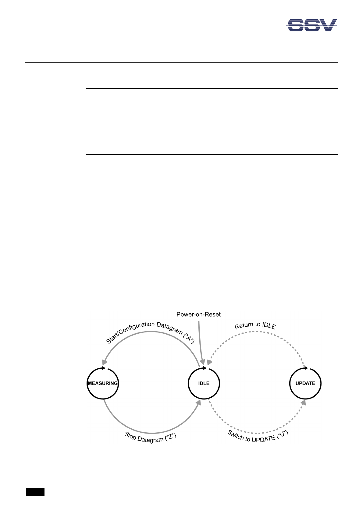
.2 Operating states
IDLE
This is the reset state of the MLS/160A. The MLS/160A waits for a configuration datagram
from the remote station. After receiving a valid configuration datagram the MLS/160A
switches to the MEASURING state. Invalid datagrams will be ignored.
MEASURING
The sensors of the MLS/160A are cyclically polled with the configured sample rate. The
measuring data is sent within a measuring datagram to the remote station. If the
MLS/160A receives a stop datagram during the time with no transmission it returns to the
IDLE state.
UPDATE
If the MLS/160A is in the IDLE state and receives the start update datagram from the re-
mote station, it switches to the UPDATE state and the update process begins. After the up-
date the MLS/160A returns to the IDLE state. Please refer to chapter 5.3 for a detailed de-
scription of the update process.
Figure 6: State machine diagram

MLS/160A – System Reference
D o c u m e n t R e v i s i o n 1 . 1
13
.3 Datagrams
Configuration
This datagram has a fixed length of 5 bytes and is transferred at the beginning of the meas-
uring from the remote station to the MLS/160A.
Bit
7
6
5
4
3
2
1
0
Byte
0x41: A
0
HUM
TEMP
G
YRZ
GYRY
GYRX
ACCZ
ACCY
ACCX
1
SAMPLE RATE
2
…
3
CRC
4
Table 8: Configuration datagram
• A: The ASCII character A (0x41) is the identifier of the configuration datagram.
• ACCX .. Z, GYRX .. Z, TEMP, HUM: These enable bits define which measurement
values of the sensors are used. At least one value must be activated, otherwise the
configuration is invalid and will be ignored.
• SAMPLE RATE: Desired sample rate in Hz as 16-bit unsigned integer (uint16) in lit-
tle endian mode. The maximum rate is calculated with the following formula:
f
max
= 115200/2 +3 (N = number of active channels)
If the desired sample rate is higher than the maximum rate, the configuration is in-
valid and will be ignored.
• CRC: CRC8 checksum over all preceding bytes.
Polynom:
f(x) = x
8
+ x
2
+ x + 1 (The bits are processed from MSB to LSB)
Example: CRC8('A') = 0xC0.

MLS/160A – System Reference
14
D o c u m e n t R e v i s i o n 1 . 1
Measuring
This datagram is sent from the MLS/160A to the remote station after each measurement. It
has a variable length depending on the configuration. If the respective measurement value
is configured to be polled, the value will be transferred, otherwise the field is left out.
Bit
7
6
5
4
3
2
1
0
Byte
0x4D: M
0
READI G ACCX (opt. BMI160)
?
?
READI G ACCY (opt. BM
I160)
?
?
READI G ACCZ (opt. BMI160)
?
?
READI G GYRX (opt. BMI160)
?
?
READI G GYRY (opt. BMI160)
?
?
READI G GYRZ (opt. BMI160)
?
?
READI G TEMP (opt. BME280)
?
?
READI G HUM (opt. BME280)
?
?
CRC
?
Table 9: Measuring datagram
• M: The ASCII character M (0x4D) is the identifier of the measuring datagram.
• READI G ACCX .. Z, READI G GYRX .. Z: Measured value of the BMI160 sensor as
16-bit unsigned integer (uint16) in little endian format.
• READI G TEMP, READI G HUM: Measured value of the BME280 sensor as 16-bit
unsigned integer (uint16) in little endian format.
• CRC: CRC8 checksum over all preceding bytes. Polynom: see above.
Stop
This datagram with the ASCII character Z (0x5A) is sent from the remote station to stop the
measurement and has a length of 1 byte. Because the MLS/160A‘s RS485 interface works in
half duplex mode it receives incoming messages only during intermissions. Therefore the
stop datagram is sent sufficiently fre uent. The stop datagram has no effect in the IDLE
state and will be ignored.
Bit
7
6
5
4
3
2
1
0
Byte
0x5A: Z
0
Table 10: Stop datagram
MLS/160A – System Reference
D o c u m e n t R e v i s i o n 1 . 1
15
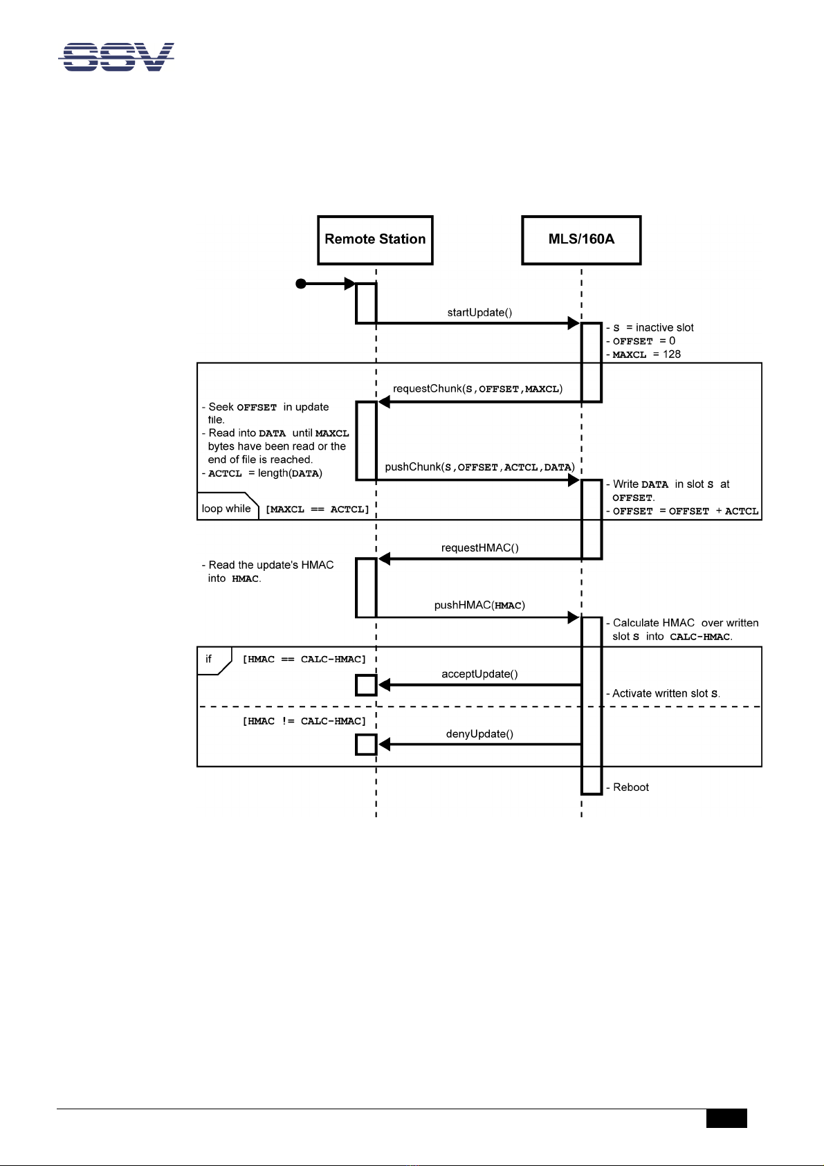
Update
During the update process several datagrams are sent between the remote station and the
MLS/160A. Figure 7 shows the update process in a diagram.
Figure 7: Diagram of the update process

MLS/160A – System Reference
16
D o c u m e n t R e v i s i o n 1 . 1
startUpdate )
To initialize an update the remote station sends a start update datagram of 1 byte length
with the ASCII character U (0x55) to the MLS/160A.
Length in Bytes
1
0x55
:
U
Table 11: Start update datagram from the remote station
requestChunk )
The MLS/160A switches from the IDLE in the UPDATE state and answers with a request
datagram of 9 bytes length.
Length in Bytes
1
1
4
2
1
R
S
OFFSET
M
AX
C
L
CRC
Table 12: Request datagram from the MLS/160A
• R: The ASCII character R (0x52) is the identifier of the re uest datagram.
• S: This byte defines the boot slot to be updated.
• OFFSET: These 4 bytes define the offset of the firmware binary file in bytes (little
endian).
• MAXCL: These 2 bytes define the maximum chunk length of the firmware binary
file in bytes (little endian); in this case 128 bytes.
• CRC: This byte contains the CRC8 checksum over all preceding bytes.
pushChunk )
The remote station answers with a page datagram which contains the first chunk of the
new firmware binary file.
Length in
Byte
s
1
1
4
2
<
=
128
1
P
S
OFFSET
A
CT
C
L
DATA
CRC
Table 13: Page datagram from the remote station
• P: The ASCII character P (0x50) is the identifier of the page datagram.
• S: This byte defines the boot slot to be updated.
• OFFSET: These 4 bytes define the offset of the firmware binary file in bytes (little
endian).
• ACTCL: These 2 bytes contain the actual chunk length of the firmware binary file in
bytes (little endian).
MLS/160A – System Reference
D o c u m e n t R e v i s i o n 1 . 1
17
• DATA: This part has a variable length and contains the chunk of the firmware bina-
ry file. Its maximum length is defined by the preceding re uest datagram.
• CRC: CRC8 checksum over all preceding bytes.
After receiving the page datagram the MLS/160A compares the MAXCL with the ACTCL. If
both lengths are e ual the MLS/160A sends a new re uest datagram with an adjusted OFF-
SET and the remote station sends a new page datagram with the next chunk of the firm-
ware binary file.
This loop runs until ACTCL is smaller than MAXCL which means that the firmware binary
file was transferred completely.
requestHMAC )
In this case the MLS/160A sends a verification datagram of 1 byte length with the ASCII
character V (0x56) to the remote station.
Length in Bytes
1
0x5
6
:
V
Table 14: Verification datagram from the MLS/160A
pushHMAC )
The remote station answers with the SHA256 HMAC (Keyed-Hash Message Authentication
Code) of the new firmware binary file.
Length in Bytes
1
256
1
H
HMAC
CRC
Table 15: HMAC datagram from the remote station
• H: The ASCII character H (0x48) is the identifier of the HMAC datagram.
• HMAC: This part contains the SHA256 HMAC of the new firmware binary file.
• CRC: CRC8 checksum over all preceding bytes.
The MLS/160A calculates the SHA256 HMAC of the new firmware (“CALC-HMAC”) and
compares it with the HMAC received from the remote station. The CALC-HMAC must be
identical with the received one in order to be valid.

MLS/160A – System Reference
18
D o c u m e n t R e v i s i o n 1 . 1
acceptUpdate )
If the HMAC is valid, the magic number of the updated slot is set back to "RIOT" and the
slot is valid again and ready to boot. The MLS/160A sends an okay datagram of 1 byte
length with the ASCII character Y (0x59) to the remote station.
Length in Bytes
1
0x59
: Y
Table 16: Okay datagram from the MLS/160A
denyUpdate )
If the HMAC is invalid, the magic number of the updated slot is not changed and the slot
remains invalid. The MLS/160A sends an error datagram of 1 byte length with the ASCII
character N (0x4E) to the remote station.
Length in Bytes
1
0x4E
:
Table 17: Error datagram from the MLS/160A
Reboot
The update process is finished and the state machine of the MLS/160A reboots and returns
to the IDLE mode.

MLS/160A – System Reference
D o c u m e n t R e v i s i o n 1 . 1
19
6 MECHANICAL DIMENSIONS
All length dimensions have a tolerance of 0.5 mm.
Figure 8: Mechanical dimensions of MLS/160A

MLS/160A – System Reference
20
D o c u m e n t R e v i s i o n 1 . 1
7 CONNECTING TO AN RMG/941
Connect the MLS/160A to an RMG/941 gateway like shown in figure 9.
Figure 9: Wiring diagram for the connection of the MLS/160A to an RMG/941
Wire color
Pin
MLS/160A
Pin
RMG/941
White
1 (Vin 24 VDC)
A3 (
Vin 24 VDC
)
Brown
2 (G Din)
A4 (Ground)
Green
3 (
485P+
)
A1 (
COM2 Serial Port: RS485 RX /TX+
)
Yellow
4 (
485P
-
)
A2 (
COM2 Serial Port: RS485 RX /TX
-
)
Table 18: Signal assignment of the wires
Table of contents


