SSZN SR Series User manual

SR Series 3D Camera
——Quick Start Guide

Shenzhen Sincevision Technology Co.Ltd
www.cnsszn.com
2/43
Quick Start Guide of SR Series ©2021 SSZN All Right Reserved
Catalogue
SR6000/SR7000/SR8000 Series 3D Camera...........................................................................................................1
——Quick Start Guide.....................................................................................................................................1
1 Preparation before Installation......................................................................................................................... 3
2 Camera Description..........................................................................................................................................4
2.1 Description of Camera SR6000........................................................................................................... 4
2.2 Description of Camera SR7000........................................................................................................... 5
2.3 Description of Camera SR8000........................................................................................................... 6
3 Controller Description......................................................................................................................................6
4 Precautions for Mounting the Camera............................................................................................................. 7
5 Precautions for cable use..................................................................................................................................8
6 Hardware Connection.....................................................................................................................................10
6.1 System Connecting Diagram............................................................................................................. 10
6.1.1 Connection method for continuous trigger mode.......................................................................... 12
6.1.2 Connection method for external trigger mode...............................................................................13
6.1.3 Connection method for encoder trigger mode............................................................................... 14
6.1.4 Cautions for wiring........................................................................................................................ 15
6.2 Connecting the controller and the Camera........................................................................................ 17
6.3 Connecting the Power Supply to the Controller................................................................................ 17
6.4 How to Use the Terminal Block.........................................................................................................18
7 Software Connection...................................................................................................................................... 20
7.1 Install EdgeImaging software............................................................................................................ 20
7.2 Connecting the controller and the PC................................................................................................ 21
8 Product Selection............................................................................................................................................23
9 Dimensions.....................................................................................................................................................27

Shenzhen Sincevision Technology Co.Ltd
www.cnsszn.com
3/43
Quick Start Guide of SR Series ©2021 SSZN All Right Reserved
Be sure to read this guide before use.
This guide aims to provide instructions for user to use the SR series 3D cameras quickly.
For detailed user’s guide, you can download the Hardware Manual of SR Series 3D Camera from
SSZN official home page website at http://www.cnsszn.com.
Please read the detailed user’s guide to understand the SR series 3D camera fully.
This guide is subject to change without individual notice.
Do not tear up the label, otherwise,we are not responsible for warranty repair.
Do not disassemble the camera, or it will damage the camera, and cause the factory
calibration data error, must be returned to the manufacturer for repair.
Be sure to read this guide carefully, incorrect operation may cause damage to the
camera.
Environmental Requirements
Keep away from the strong electromagnetic noise source such as a high-power equipment and
high-voltage line.
Avoid sharing power source with the high-power equipment.
Avoid laying the Camera cable and the Ethernet cable in parallel with the power lines.
1 Preparation before Installation
Before installation, first, please prepare the following items:
Ethernet Cable (category 6 or higher or compatible with 10GBase-T)
Multimeter
Wire Stripping Plier
Wire Crimping plier
Flat Gasket, M4 x4
A set of Flathead Screwdrivers
A set of Cross Screwdrivers
A set of Hex Key Allen Wrench

Shenzhen Sincevision Technology Co.Ltd
www.cnsszn.com
4/43
Quick Start Guide of SR Series ©2021 SSZN All Right Reserved
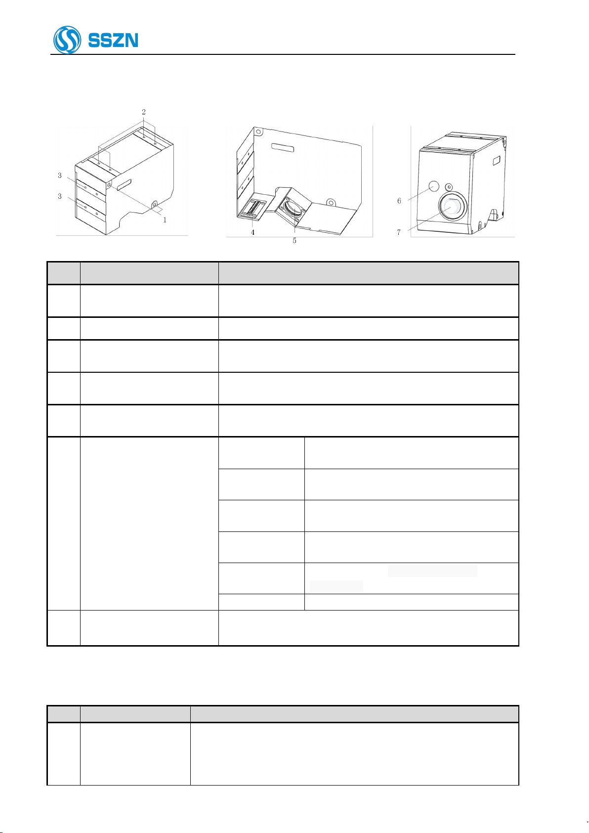
2 Camera Description
2.1 Description of Camera SR6000
Item
Name
Description
1
Laser-emitting LED
Lights green
The target object is at around the center of the Z
axis measurement area.
Lights orange
The target object is in the Z axis measurement
area.
Blinks orange
The target object is out of the specified Z axis
measurement area.
Lights green or
orange
The laser is working.
Lights off
Power off, or the power supply is failed
or abnormal.
Lights red
Any system error occurred at the camera.
2
Special mounting holes
The screw holes can be used to mount the camera.
3
Mounting holes
Use the hexagon socket bolt (included) to affix the camera.
Please refer to “4 Precautions for Mounting the Camera”.
4
Mounting holes for the stray
light shield
Use the holes to mount a plate for blocking stray light. Do not use for
mounting the camera.
5
Sensor (receiver)
Receive the laser beam for measurement.
Protected by a glass cover.
6
Sensor (transmitter)
Emit the laser beam for measurement.
Protected by a glass cover.
7
Cable connector
Connected with the camera cable.
Please refer to “6.2 Connecting the controller and the Camera”.

Shenzhen Sincevision Technology Co.Ltd
www.cnsszn.com
5/43
Quick Start Guide of SR Series ©2021 SSZN All Right Reserved
2.2 Description of Camera SR7000
1
2
3
4
4
5
6
7
Item
Name
Description
1
Laser-emitting LED
Lights green
The target object is at around the center of the Z
axis measurement area.
Lights orange
The target object is in the Z axis measurement
area.
Blinks orange
The target object is out of the specified Z axis
measurement area.
Lights green or
orange
The laser is working.
Lights off
Power off, or the power supply is failed
or abnormal.
Lights red
Any system error occurred at the camera.
2
Special mounting holes
The screw holes can be used to mount the camera.
3
Mounting holes
Use the hexagon socket bolt (included) to affix the camera.
Please refer to “4Precautions for Mounting the Camera”.
4
Mounting holes for the stray
light shield
Use the holes to mount a plate for blocking stray light. Do not use for
mounting the camera.
5
Sensor (receiver)
Receive the laser beam for measurement.
Protected by a glass cover.
6
Sensor (transmitter)
Emit the laser beam for measurement.
Protected by a glass cover.
7
Cable connector
Connected with the camera cable.
Please refer to “6.2 Connecting the controller and the Camera”.
Shenzhen Sincevision Technology Co.Ltd
www.cnsszn.com
6/43
Quick Start Guide of SR Series ©2021 SSZN All Right Reserved
2.3 Description of Camera SR8000
Item Name Description
1 Mounting holes Use the hexagon socket bolt (included) to affix the camera.
Please refer to “4Precautions for Mounting the Camera”.
2 Special mounting holes The screw holes can be used to mount the camera.
3Mounting holes for the stray
light shield
Use the holes to mount a plate for blocking stray light. Do not use for
mounting the camera.
4 Sensor (transmitter) Emit the laser beam for measurement.
Protected by a glass cover.
5 Sensor (receiver) Receive the laser beam for measurement.
Protected by a glass cover.
6 Laser-emitting LED
Lights green The target object is at around the center of the Z
axis measurement area.
Lights orange The target object is in the Z axis measurement
area.
Blinks orange The target object is out of the specified Z axis
measurement area.
Lights green or
orange The laser is working.
Lights off Power off, or the power supply is failed
or abnormal.
Lights red Any system error occurred at the camera.
7 Cable connector Connected with the camera cable.
Please refer to “6.2 Connecting the controller and the Camera”.
3 Controller Description
Item Name Description
1 I/O terminal block
Used for controlling signal input or output.
Used for pulse signal input from the encoder.
Used for RS-232 connection;
and used for power supply of I/O insulating part.

Shenzhen Sincevision Technology Co.Ltd
www.cnsszn.com
7/43
Quick Start Guide of SR Series ©2021 SSZN All Right Reserved
Please refer to “Hardware Manual of SR Series 3D Camera”.
2
24V power input
terminal block
Used for supply of the power source (DC24V).
Left: +24V, middle: 0V, right: Shell and GND
3
Ethernet port RJ45
connector
Connect to a personal computer or a switch with the Ethernet cable. (RJ-45
connector)
4
Camera connector
Connect to cameras with the camera cable, including camera-A connector
and camera-B connector.
Please refer to “6.2 Connecting the controller and the Camera”.
5
Reserved
Do not use, or it will damage the controller
6
USB2.0 port
Reserved
7
VGA port
Reserved
8
POWER ON LED
Showing the power
status, blue LED.
ON
The controller is powered on normally
OFF
Power off, or the power supply is
abnormal.
9
RUN LED
Showing the controller
works status, green
LED.
Blink
The controller is in the normal
operation state.
OFF
Power off, or the controller
is abnormal.
10
ERROR LED
Showing the controller
error status, red LED.
ON
Any error occurs.
OFF
The controller is normal.
Controller Model
Description
SR7001
Support SR6000 and SR7000 Camera
SR7002
Only support SR8000 Camera
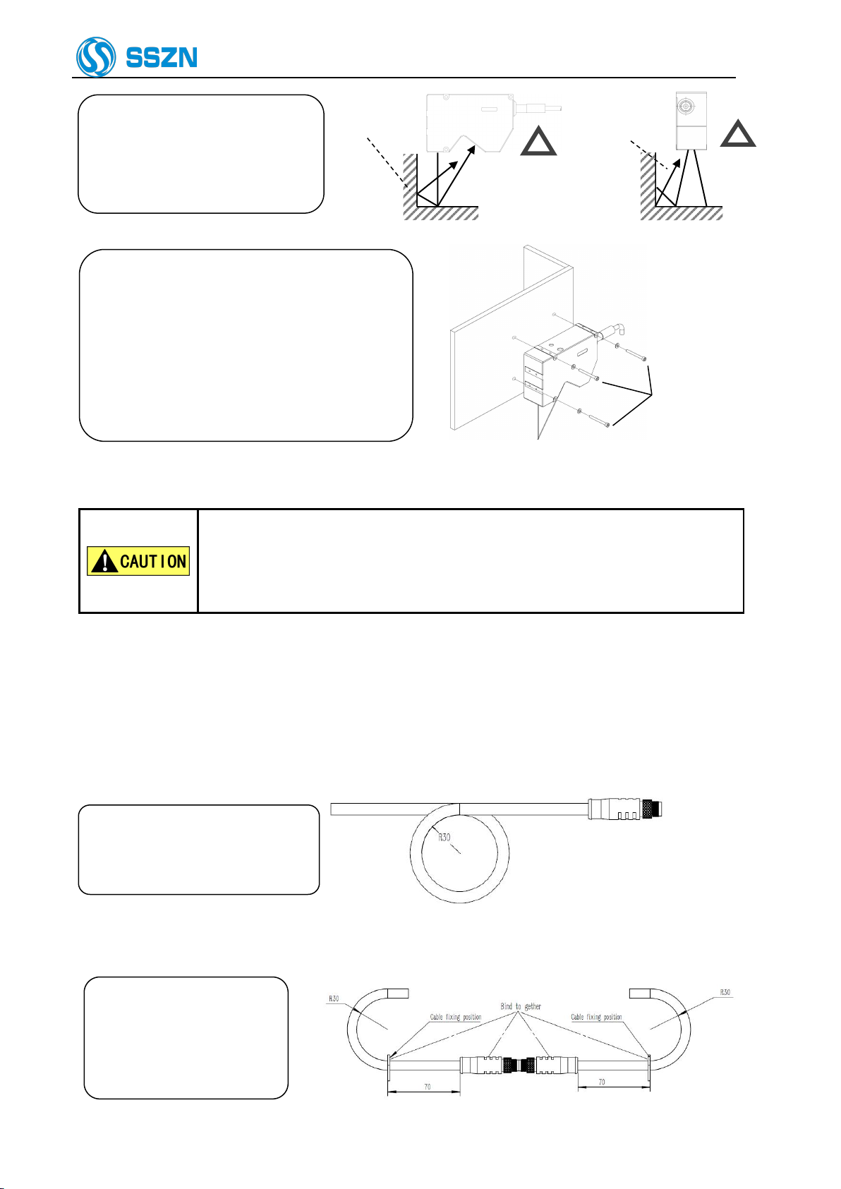
4 Precautions for Mounting the Camera
Figure 4- 1 Dead Zone Arises
When installing the camera, make sure that the laser
beam irradiating the target object and the laser beam
reflected from the target object into the receiver, are
not obstructed by a wall surface, etc.
Figure 4- 2 Laser Beam Optical Path Obstructed
Depending on their shape, some target objects create a
dead zone in the measurement range. Make sure that the
dead zone does not affect the measurement result.
This unit features a fan shaped laser beam and receiver
system. For this reason, the dead zone will be smaller
near the center of the X-axis measurement range.
Shenzhen Sincevision Technology Co.Ltd
www.cnsszn.com
8/43
Quick Start Guide of SR Series ©2021 SSZN All Right Reserved
Stray light
Stray ligh
The laser reflected on the wall
will become stray light. Make
sure that the stray light will
not affect the measurement
Figure 4- 3 Generation of Stray light
Adjust the distance between the camera and
the target object, and then mount the camera
using the provided bolts.
For mounting dimensions, please refer to “9
Dimensions”
The tightening torque of the mounting screws
should be in the following ranges:
M4 screw: 1.2 ~1.8 N · m
Hexagon socket
head bolt
M4x55: 3 bolts
Figure 4- 4 Mounting the Camera
If you mount the camera on a plate made from material having poor heat
dissipation properties (such as resin), the camera surface may become hot, which
may cause a burn hazard.
Be sure to connect the camera to a metallic plate for better heat dissipation.
When using two cameras, pay attention to mutual interference area to prevent mutual interference from each
other. For more information, please refer to “Software Manual of SR Series 3D Camera” provided together
with the product.
5 Precautions for cable use
Please ensure that the minimum
bending radius of the camera cable
is more than 30mm
Figure 5- 1 Schematic diagram of minimum bending radius of cable
When using cable connection,
the connector and the cable
within 70mm at both ends
must be kept relatively
stationary.
Figure 5- 2 Schematic diagram of cable connection
Shenzhen Sincevision Technology Co.Ltd
www.cnsszn.com
9/43
Quick Start Guide of SR Series ©2021 SSZN All Right Reserved
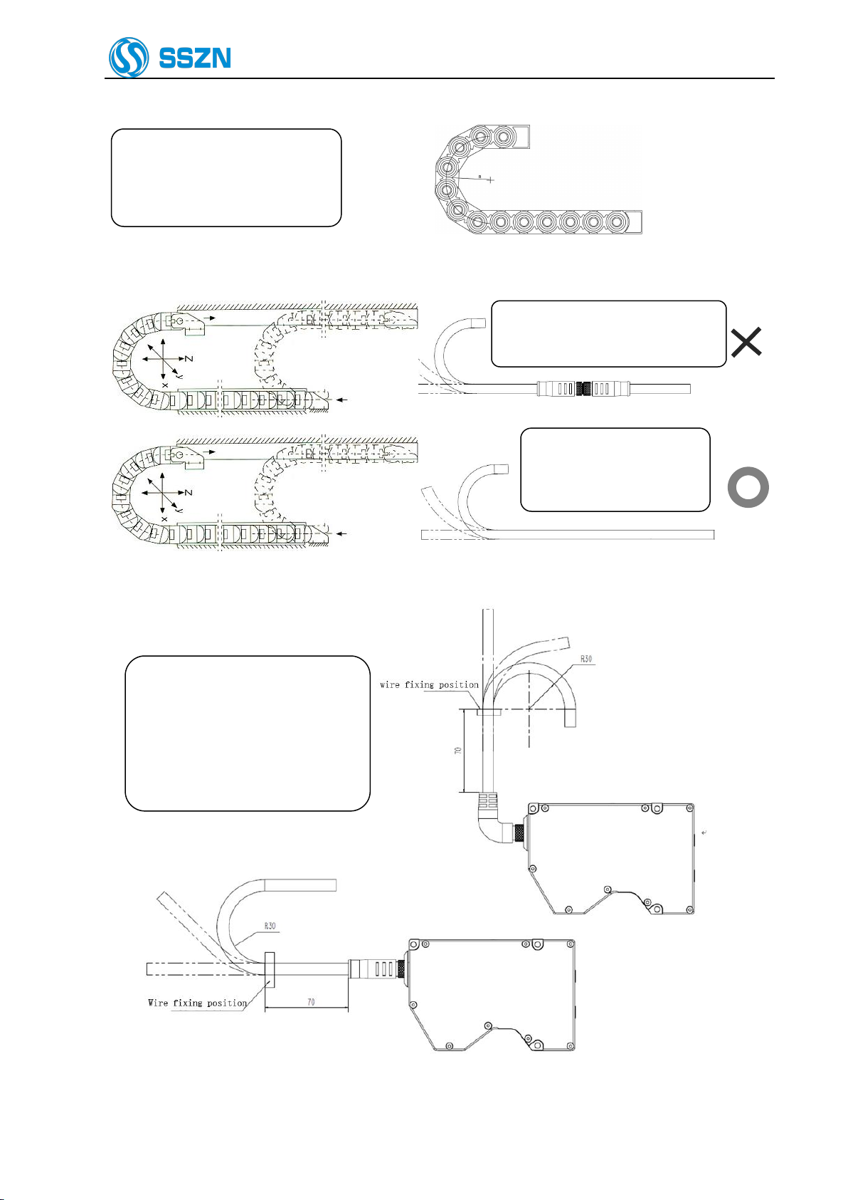
If there is no special specification
when using drag chain, please
select products above R100.
R100
Figure 5- 3 Schematic diagram of minimum bending radius of cable
Cables with connection points shall
not be used on the drag chain.
&
&
When using drag chains,
choose cables without
connection points
Figure 5- 4 Selection Diagram for Cable Drag Application
Figure 5- 5 Fixed Camera and Camera Cable Diagram
The cable must be fixed on the
same bracket as the camera about
70mm from the connector plug to
keep it relatively static with the
camera.

Shenzhen Sincevision Technology Co.Ltd
www.cnsszn.com
10 /43
Quick Start Guide of SR Series ©2021 SSZN All Right Reserved
Make sure that the connector plug and the cable within a minimum of 70mm remain relatively
static with the camera.
6 Hardware Connection
6.1 System Connecting Diagram
Figure 6- 1 System Connecting Diagram
Always make sure to switch OFF the controller before connecting or removing
cables. Connecting or removing cables with the controller switched ON may
result in a malfunction.
Plug in the connector after making sure its orientation is correct. Inserting the
connector in the wrong orientation may break the connector pins and result in
a malfunction.
Only one camera controller can be connected to an encoder output; When

Shenzhen Sincevision Technology Co.Ltd
www.cnsszn.com
11 /43
Quick Start Guide of SR Series ©2021 SSZN All Right Reserved
multiple camera controllers are required to share a single encoder, an Encoder
Pulse Signal Allocator is required to expand the encoder signal to multiple
outputs and then connect the corresponding camera controllers separately.
Different control requirements of the system correspond to different connection modes, select the
corresponding wiring diagram to connect on the basis of “Trigger mode” and “Batch start mode”, please refer
to “Figure 6 2 I/O Terminal Wiring Diagram 1”, “Figure 6 2 I/O Terminal Wiring Diagram 1” and “Figure 6 3
I/O Terminal Wiring Diagram 3”. For the “Trigger mode” Setting in EdgeImaging, please refer to “Software
Manual of SR Series 3D Camera”.

Shenzhen Sincevision Technology Co.Ltd
www.cnsszn.com
12 /43
Quick Start Guide of SR Series ©2021 SSZN All Right Reserved
6.1.1 Connection method for continuous trigger mode
Figure 6- 2 I/O Terminal Wiring Diagram 1
Shenzhen Sincevision Technology Co.Ltd
www.cnsszn.com
13 /43
Quick Start Guide of SR Series ©2021 SSZN All Right Reserved
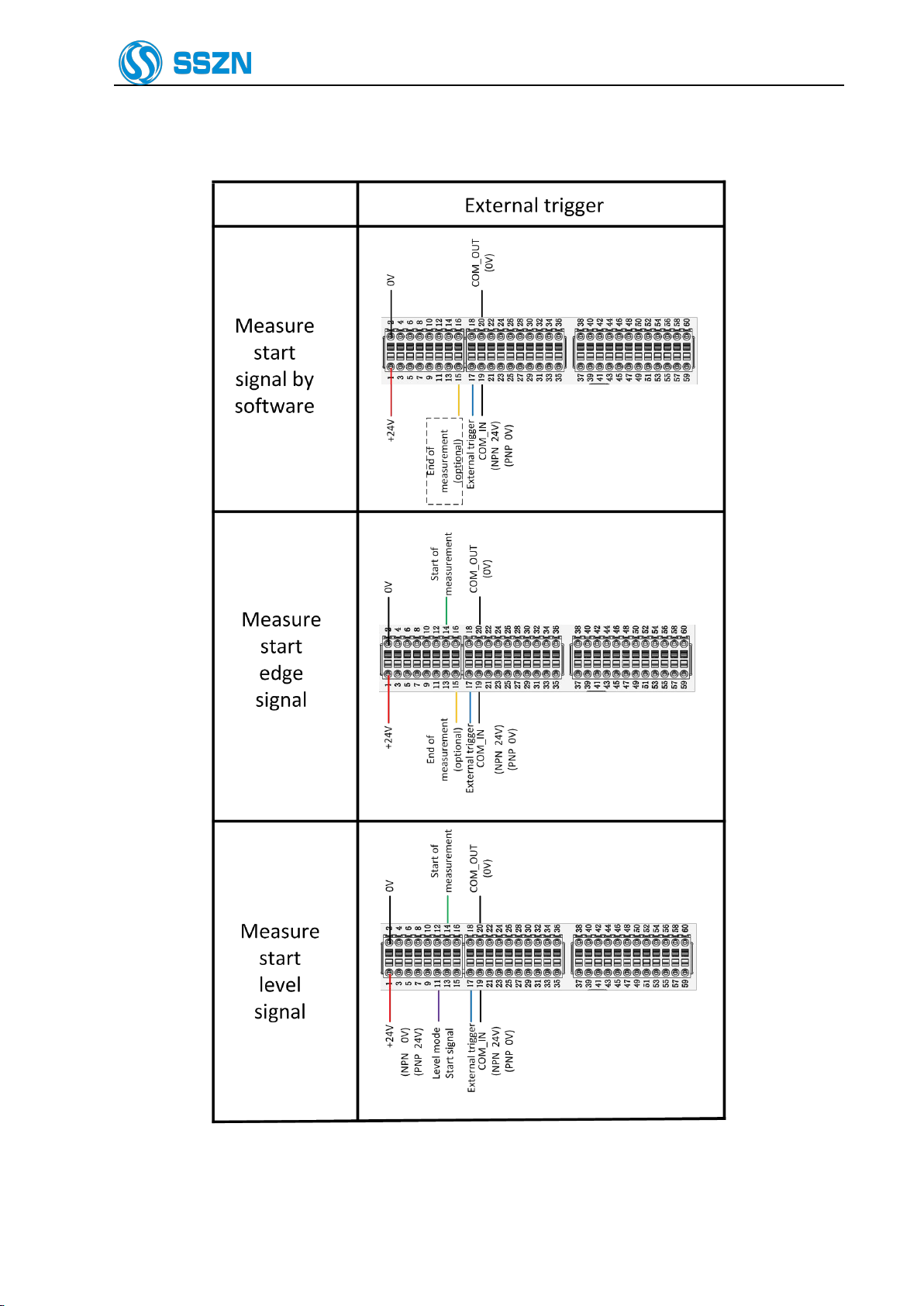
6.1.2 Connection method for external trigger mode
Figure 6- 3 I/O Terminal Wiring Diagram 2
Shenzhen Sincevision Technology Co.Ltd
www.cnsszn.com
14 /43
Quick Start Guide of SR Series ©2021 SSZN All Right Reserved
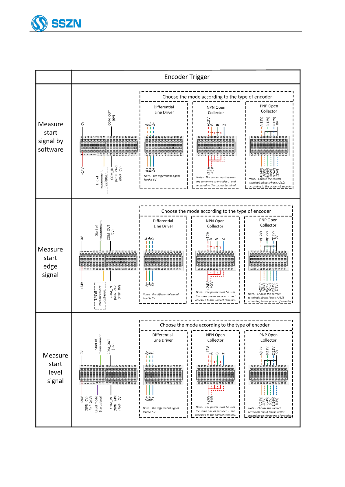
6.1.3 Connection method for encoder trigger mode
Figure 6- 3 I/O Terminal Wiring Diagram 3

Shenzhen Sincevision Technology Co.Ltd
www.cnsszn.com
15 /43
Quick Start Guide of SR Series ©2021 SSZN All Right Reserved
6.1.4 Cautions for wiring
1. Terminal connection must not be live operation, do not supply power to the controller, and ensure that the
PLC, servo driver, etc. are in power off status. Hot plug terminal stage will cause controller damage.
2. 3-17 PIN are input ports, combined with PIN19 "COM_IN"; 21~36 PIN are output ports, combined with
20 feet "COM_OUT".
a) Input port and PIN19 wiring instructions:
PLC Leakage Output (NPN) Local Input Circuit PLC Source Output(PNP) Local Input Circuit
b) Output port and PIN20 connection instructions:
Local Output Circuit PLC Input Circuit(Positive Common End)
3. In the connection method using edge signal, PIN14 and PIN15 need to connect to 0V in order to avoid
triggering by mistake when they are not used.
4. When there is no input in PIN11, the start of measurement (PIN14) and end of measurement (PIN15) work
in edge mode. Figure 65 shows the time sequence diagram for signals.
Figure 6- 5 Time sequence diagram for Edge Mode
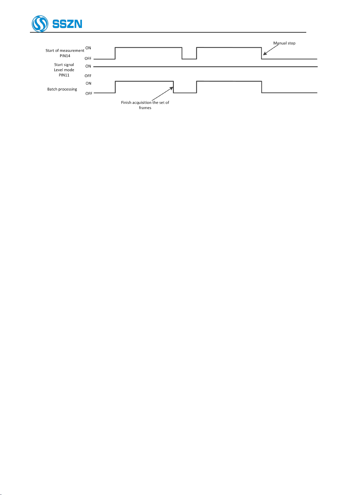
5. When there is a input signal in PIN11 all the time, the start of measurement (PIN14) works in level mode
and the end of measurement (PIN15) is invalid. Figure 6-6 shows the signal sequence diagram.
Shenzhen Sincevision Technology Co.Ltd
www.cnsszn.com
16 /43
Quick Start Guide of SR Series ©2021 SSZN All Right Reserved
Figure 6- 6 Time sequence diagram for Level Mode

Shenzhen Sincevision Technology Co.Ltd
www.cnsszn.com
17 /43
Quick Start Guide of SR Series ©2021 SSZN All Right Reserved
6.2 Connecting the controller and the Camera
This section explains the procedure for connecting the controller and the camera.
Do not supply power to the controller before connecting the camera cable.
Connecting the camera cable while the controller is switched ON may damage
the camera and/or the controller.
Maintain a minimum bend radius of 30 mm or more for the camera cable,
and the connectors at both ends should not be in tension state.
When using a cable tray, select a model with R100 or higher unless specified
otherwise.
Step1 Connect the camera cable to the camera connector of the controller.
Figure 6- 7 Connecting the Camera Cable to the Controller
Step2 Connect the camera cable and the camera.
Check the orientation of the
connector, and then insert it all the
way while slowly rotating it. Tighten
the screw with a tightening torque of
1 to 1.5 N·m.
Figure 6- 8 Connecting the camera cable and the camera
Plug in the connector after making sure its orientation is correct. Inserting the
connector in the wrong orientation may break the connector pins and result in
a malfunction.
Insert the connector without tilting it, and then tighten it firmly. If the
connector is not tightened enough, it may become loose due to vibration, etc.
resulting in poor contact.
Tighten it firmly by hand and then retighten approx. 45° to 60°.
6.3 Connecting the Power Supply to the Controller
This section explains the procedure for connecting the controller and the power supply.
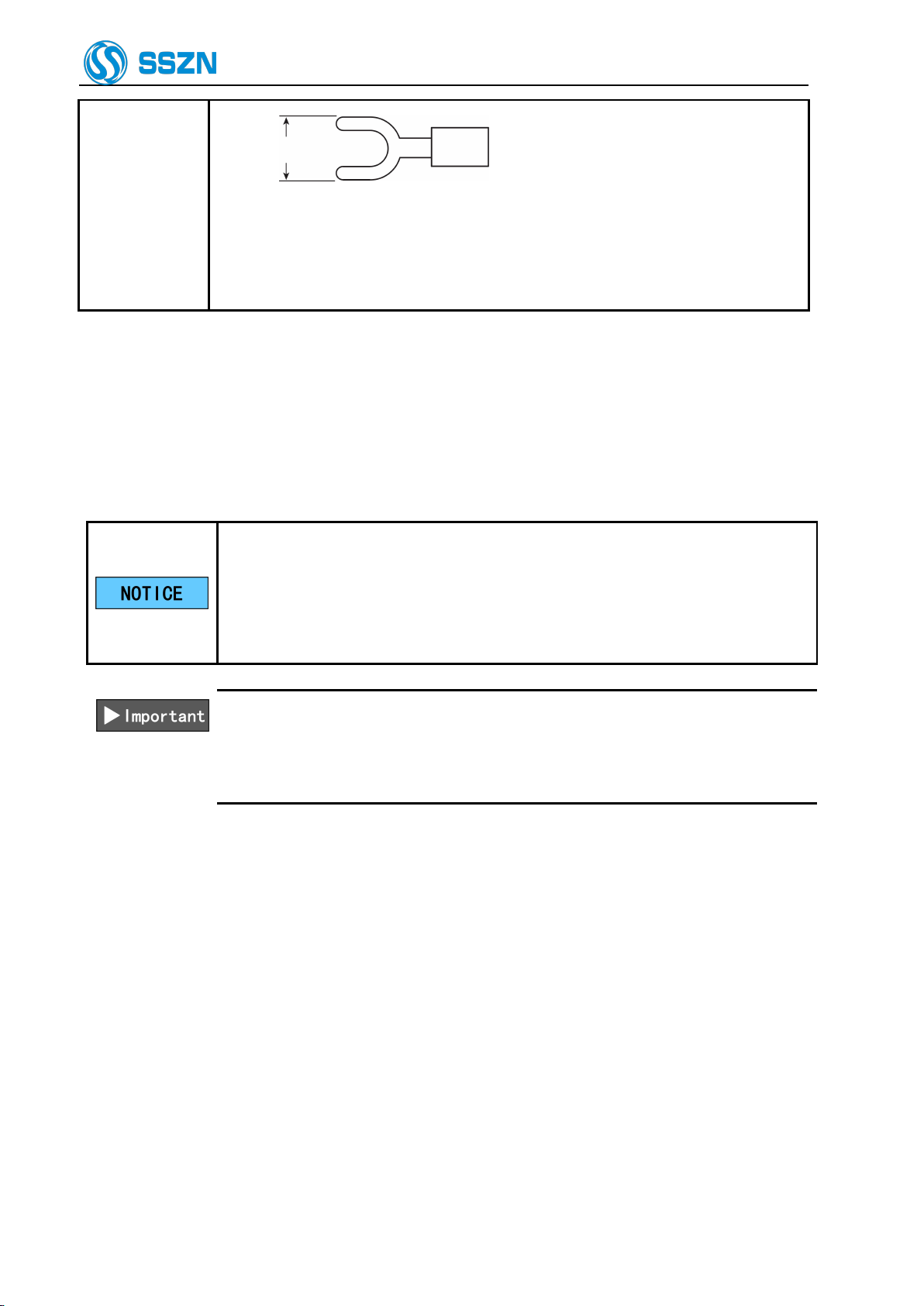
Use a wire between AWG14 and AWG20.
If you are using a solderless terminal, use a terminal that has the following size
and suits the M3 screw:
If only one camera is used, connect it
to the CAM A connector. Tighten the
screws on both sides of the connector
with a flathead screwdriver. Make sure
it is fixed firmly.
Shenzhen Sincevision Technology Co.Ltd
www.cnsszn.com
18 /43
Quick Start Guide of SR Series ©2021 SSZN All Right Reserved
Y terminal
6.4mm or less
Tighten the screw firmly with a tightening torque of 0.5 to 0.75 [N·m].
The DC24V power supply must be 60W or more(include 2 cameras).
(notice :if only have one controller with one camera ,the power supply must be
30W or more ).
Step1 Connect the 24 V DC power supply to the 24 V power supply terminal of the controller.
6.4 How to Use the Terminal Block
This section explains how to use the terminal block.
IO power supply of controller terminal must share power supply with PLC and
servo driver.
Terminal block wiring should not be operated live, please do not supply power
to the controller, and ensure that the PLC, servo driver are in a power-off state.
Hot plug terminal stage will cause controller damage..
Use a wire between AWG16 and AWG28.
The end of the wire should be processed to the length approx. 8 mm.
Do not solder (pre-solder) the processed end of the wire.
The wire should be inserted all the way into the terminal block.
Step1 Insert the wire into “part b” while pushing in “part a” of the terminal block with a flathead
screwdriver.

Shenzhen Sincevision Technology Co.Ltd
www.cnsszn.com
19 /43
Quick Start Guide of SR Series ©2021 SSZN All Right Reserved
When the wire is inserted to
the end of “part b”, remove
the screwdriver. Then lightly
pull the wire to make sure it is
fixed firmly.
b
a
Terminal
block
Figure 6- 10 Terminal Block Wiring Diagram
Step 2 When the wire is inserted to the end, remove the screwdriver. Then lightly pull the wire to make
sure it is fixed firmly.

Shenzhen Sincevision Technology Co.Ltd
www.cnsszn.com
20 /43
Quick Start Guide of SR Series ©2021 SSZN All Right Reserved
7 Software Connection
7.1 Install EdgeImaging software
1. The required computer environment is as follows:
Hardware
requirements
CPU
Core i5 2.3 GHz or higher
Memory Size
8 GB or more
Level 2 cache
2 MB or more
Hard disk space
10GB or more
Interface
Ethernet 1000BASE-T/100BASE-TX
Displayer
XGA(1024*768 pixels)or more,256-color or more
Software
requirements
Operating system
Windows 10 32/64bit Professional/Enterprise
Windows 8.1 32/64bit Professional/Enterprise
Windows7 32/64bit Professional/Ultimate
2. Obtain the installation package of EdgeImaging software from the manufacturer.
3. Enter the windows system,double click the installation package of EdgeImaging.
4. Follow the steps in the installation wizard.
Figure 7- 1
5. On the Finish page, click Finish to exit.Then, the EdgeImaging software is installed successfully.
Figure 7- 2
Other manuals for SR Series
1
This manual suits for next models
16
Table of contents
Other SSZN 3D Camera manuals


