SSZN SR Series User manual
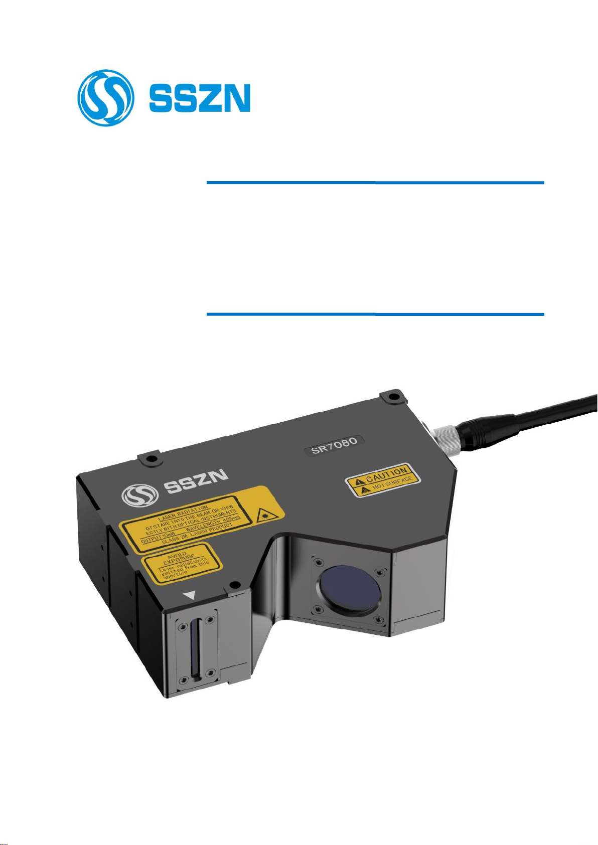
SR Series 3D Camera
——Hardware Manual
V2.3.4
2021.5
www.cnsszn.com

CNSSZN Technology Ltd.
www.cnsszn.com
2/63
Hardware Manual of SR Series © 2021 SSZN All Right Reserved
Copyright Statement
CNSSZN Technology Ltd.
All rights reserved.
CNSSZN Technology Ltd. (hereinafter referred to as SSZN) reserves the right to modify the
products and product specifications described in this manual without prior notice.
SSZN will not be responsible for any direct, indirect, or consequential damage or liability caused
by improper use of this manual or the product.
SSZN owns the patent, copyright or any other intellectual property right of this product and
related software. No individual or organization shall duplicate, reproduce, process or use this
product and its parts, without written authorization from SSZN.
Contact Us
CNSSZN Technology Ltd.
Telephone
: 0755-29655425
Email
:support@cnsszn.com
Website
:http://www.cnsszn.com
Address
East China Office
Industrial Park
: 5th Floor, Building2, Chongwen Industrial Park ,Nanshan Zhiyuan,
Nanshan District, Shenzhen, China.
:Room 1304, Building 7, Xiangyu Liangan Trade Center, 1588
Chuangchuan Road, Kunshan, Jiangsu Province, China.
:Zone B, 1st Floor, Chungu building, Meisheng Zhihuigu, No. 2026,
Songbai Road, Yingrenshi Community, Shiyan Street,Baoan
District, Shenzhen, China.
Postal Code
: 518063
CNSSZN Technology Ltd.
www.cnsszn.com
3/63
Hardware Manual of SR Series © 2021 SSZN All Right Reserved
Introduction
Be sure to read this user's manual before use.
After reading, keep it for future reference.
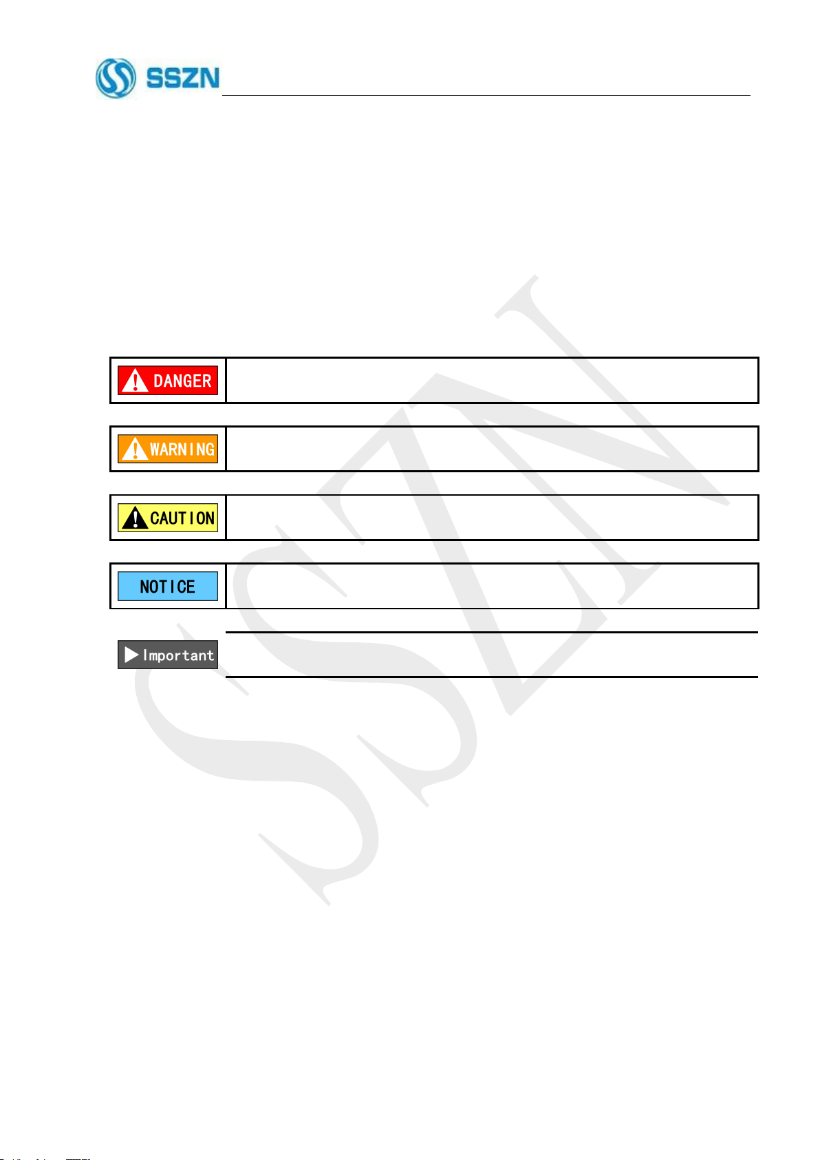
In this manual, the following symbols alert you to important messages.
Be sure to read the messages.
It indicates a hazardous situation which, if not avoided, will result in death or
serious injury.
It indicates a hazardous situation which, if not avoided, could result in death or
serious injury.
It indicates a hazardous situation which, if not avoided, could result in minor or
moderate injury.
It indicates a situation which, if not avoided, could result in product damage as well
as property damage.
It indicates cautions and limitations that must be followed during operation.
An utmost effort has been made to ensure the contents of this manual are as complete as possible. If there
are any mistakes or question, please contact SSZN sales division. Any manuals with missing pages or other paging
faults will be replaced.

CNSSZN Technology Ltd.
www.cnsszn.com
4/63
Hardware Manual of SR Series © 2021 SSZN All Right Reserved
Thank you for choosing SSZN machine vision relevant products
To repay customers, we will help you establish your own machine vision system with our first-class
machine vision products, perfect after-sale service, and high-efficiency technical support.
More information about SSZN products
Please visit our website at http://www.cnsszn.com for more information about our company and
products, including company profile, product introduction, technical support, product latest release and so
on.
You can also dial the telephone (0755-29655425) for more information about our company and
product.
Technical Support and After-sale Service
You may get our technical support and after-sale service through the following approaches:
Email
:support@cnsszn.com
Telephone
: 0755-29655425
Address
: 5th Floor, Building2, Chongwen Industrial Park ,Nanshan
Zhiyuan, Nanshan District, Shenzhen, China.
Postal Code
: 518063
Use of this Hardware User’s Manual
By reading this manual, users can understand the basic architecture of the machine vision product SR
Series 3D Camera, learn how to install the SR Series 3D Camera, wire the machine vision system with the
image processing system, motor control system, and motion control system, and conduct the basic
debugging of the machine vision system.
User of this Hardware Manual
This manual is suitable for those engineering personnel who have the basic knowledge of hardware,
and good understanding of machine vision and mechanical automation.
Main Contents of this Hardware Manual
This manual consists of six chapters. The composition ,installation, wiring, technical parameters and
troubleshooting of SR Series 3D camera are introduced in detail.
Related Documents
For the software debugging of SR Series 3D Camera, please refer to “Software Manual of SR
Series 3D Camera” and “Communication Library Reference Manual of SR Series 3D Camera” provided
together with the product.
CNSSZN Technology Ltd.
www.cnsszn.com
5/63
Hardware Manual of SR Series © 2021 SSZN All Right Reserved
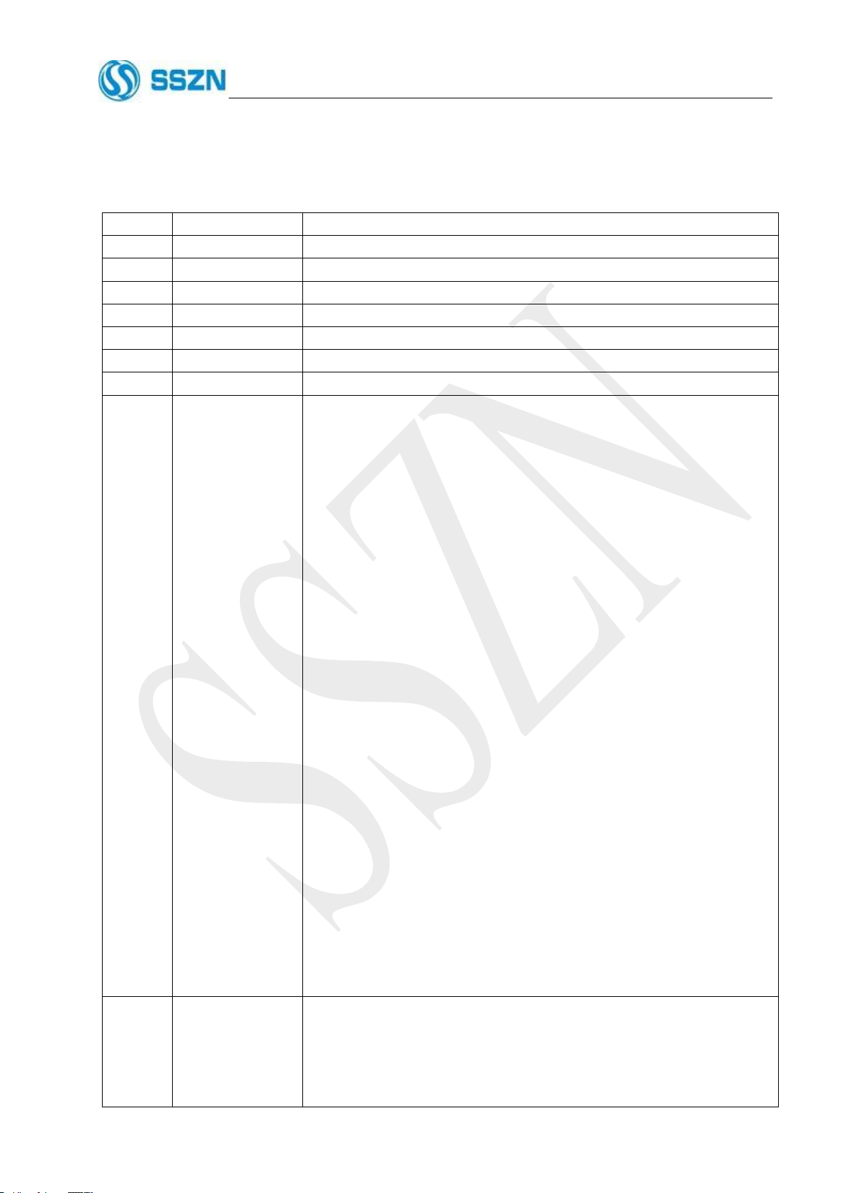
Document Version
Version
Date
Revision
1.0
August 3, 2017
2.0
October 27, 2017
2.1.0
November 15,2017
2.1.1
December 5, 2017
2.1.2
January 8, 2018
2.1.3
January 18, 2018
2.1.4
April 4, 2018
2.2.0
June 8, 2018
The following updates are suitable for the V2.1 and later versions of IO
board of controller.
Section 4.1 System Connecting Diagram :
Updated Figure 4- 2 I/O Terminal Wiring Diagram 1 and Figure 4- 3 I/O
Terminal Wiring Diagram 2.
Section 4.4 How to Use the Terminal Block :
Added notice for terminal block wiring.
Section 4.5 I/O Terminal :
Changed the definitions of terminal block pin 18, 19 and 20 in Table
4- 1 I/O Terminals Arrangement.
Section 6.1 Specifications :
Added the unit of reference distance (CD) in Table 6- 1 SR7000 Series
System Parameters.
Changed the content of Z axis height (FS) of SR7400 in Table 6- 1
SR7000 Series System Parameters.
Updated internal circuit and the wiring example in Table 6- 4
General-Purpose Input Signal Electrical Parameters.
Updated internal circuit and the wiring example in Table 6- 5
High-Speed Input Signal Electrical Parameters.
Updated internal circuit and the wiring example in Table 6- 6
General-Purpose Output Signal Electrical Parameters.
Updated internal circuit and the wiring example in Table 6- 7
High-Speed Output Signal Electrical Parameters.
Updated internal circuit and the wiring example in Table 6- 8 Encoder
(Open collector output) Input Signal Electrical Parameters.
Updated internal circuit and the wiring example in Table 6- 9 Encoder
(Differential Line Driver Output) Input Signal Electrical Parameters.
2.3.0
February 14, 2019
Section 6.1 Specifications :
Added the parameters of SR7300 in Table 6- 1 SR7000 Series System
Parameters.
Added the Table 6- 2 SR6000 Series System Parameters and Table 6- 3
SR8000 Series System Parameters.

CNSSZN Technology Ltd.
www.cnsszn.com
6/63
Hardware Manual of SR Series © 2021 SSZN All Right Reserved
Section 6.2 Dimensions:
Added the Camera SR7300 Dimension、Camera SR6030 Dimension、
Camera SR6070 Dimension、Camera SR6071 Dimension、Camera
SR6130 Dimension、Camera SR6260 Dimension、Camera SR8020
Dimension and Camera SR8060 Dimension.
2.3.1
June 14, 2019
Changed the title and file name from Hardware Manual of SR7000 Series 3D
Camera to Hardware Manual of SR Series 3D Camera.
Changed all figures and tables into the form of caption.
Section 4.5 I/O Terminal :
Changed part content of How to Use the I/O, and added hyperlinks.
Section 6.1 Specifications :
Consolidated Table 6- 4 General-Purpose Input Signal Electrical
Parameters and Table 6- 5 High-Speed Input Signal Electrical
Parameters into section 6.1.2 Input Signal Electrical Parameters.
Updated the PNP wiring example in Table 6- 4 General-Purpose Input
Signal Electrical Parameters.
Updated the PNP wiring example in Table 6- 5 High-Speed Input Signal
Electrical Parameters.
Consolidated Table 6- 6 General-Purpose Output Signal Electrical
Parameters and Table 6- 7 High-Speed Output Signal Electrical
Parameters into section 6.1.3 Output Signal Electrical Parameters.
Consolidated Table 6- 8 Encoder (Open collector output) Input Signal
Electrical Parameters and Table 6- 9 Encoder (Differential Line Driver
Output) Input Signal Electrical Parameters into section 6.1.4 Encoder
Input Signal Electrical Parameters.
Adjusted the typesetting order of section 6.2 Dimensions.
2.3.2
August 27,2020
Changed the 6.1.1 System Parameters .
Updated the Section 6.2 Dimensions.
2.3.3
May 26,2020
Changed the precautions of Section 4.2 Connecting the controller and the
camera.
Changed the linearity in Table 6-1 SR7000 series system parameters to ±
0.05%.
Changed the linearity in Table 6-2 SR6000 series system parameters to ±
0.05%.
Updated the Dimensions of 6.2.2、6.2.3、6.2.4、6.2.5、6.2.6、6.2.7、6.2.8、
6.2.11、6.2.12、6.2.13、6.2.14、6.2.15、6.2.16 and 6.2.17.
2.3.4
November19, 2021
Changed 4.5.1 I/O Terminals Block the definition and function description
about Pin11 and Pin33.

CNSSZN Technology Ltd.
www.cnsszn.com
7/63
Hardware Manual of SR Series © 2021 SSZN All Right Reserved
Contents
SR Series 3D Camera.............................................................................................................................................. 1
——Hardware Manual................................................................................................................................... 1
V2.3.4................................................................................................................................................................ 1
1 Overview...........................................................................................................................................................9
1.1 General Description............................................................................................................................ 9
1.2 Features................................................................................................................................................ 9
1.3 Products Selection Information........................................................................................................11
2 Precautions..................................................................................................................................................... 12
2.1 Safety Information............................................................................................................................ 12
2.1.1 General Safety Precautions.................................................................................................. 12
2.1.2 Safety Precautions on Laser Product.................................................................................. 13
2.2 Important Instructions..................................................................................................................... 14
2.2.1 Precautions for Use............................................................................................................... 14
2.2.2 Precautions in Emergency....................................................................................................16
2.2.3 Precautions on Installation...................................................................................................16
2.2.4 Precautions in Storing...........................................................................................................17
3 Quick Start..................................................................................................................................................... 18
3.1 Checking the Package....................................................................................................................... 18
3.2 Environmental Requirements.......................................................................................................... 19
3.3 Preparation before Installation........................................................................................................19
3.4 Part Names and Functions............................................................................................................... 20
3.4.1 Part Names and Functions of Camera................................................................................ 20
3.4.2 Part Names and Functions of Controller............................................................................21
3.5 Installation..........................................................................................................................................21
3.5.1 Mounting the Camera...........................................................................................................21
3.5.2 Mounting the Controller.......................................................................................................24
4 Hardware Connection................................................................................................................................... 27
4.1 System Connecting Diagram............................................................................................................27
4.2 Connecting the controller and the Camera.................................................................................... 30
4.3 Connecting the Power Supply to the Controller............................................................................ 31
4.4 How to Use the Terminal Block........................................................................................................31
4.5 I/O Terminal.......................................................................................................................................32
4.5.1 I/O Terminals Block.............................................................................................................. 32
4.5.2 How to Use the I/O................................................................................................................ 36
5 LED Indicator Lights.................................................................................................................................... 37
5.1 Description of the Camera LED...................................................................................................... 37
5.2 Description of the Controller LED.................................................................................................. 37
6 Appendix.........................................................................................................................................................38
6.1 Specifications......................................................................................................................................38
6.1.1 System Parameters................................................................................................................38
6.1.2 Input Signal Electrical Parameters..................................................................................... 42
6.1.3 Output Signal Electrical Parameters.................................................................................. 44

CNSSZN Technology Ltd.
www.cnsszn.com
8/63
Hardware Manual of SR Series © 2021 SSZN All Right Reserved
6.1.4 Encoder Input Signal Electrical Parameters......................................................................45
6.2 Dimensions......................................................................................................................................... 47
6.2.1 Controller SR7001 Dimension....................................................................................... 47
6.2.2 Camera SR7050 Dimension........................................................................................48
6.2.3 Camera SR7080 Dimension........................................................................................49
6.2.4 Camera SR7140 Dimension........................................................................................50
6.2.5 Camera SR7240 Dimension........................................................................................51
6.2.6 Camera SR7400 Dimension........................................................................................52
6.2.7 Camera SR7300 Dimension........................................................................................53
6.2.8 Camera SR7900 Dimension........................................................................................54
6.2.9 Camera SR71600 Dimension..................................................................................... 55
6.2.10 Camera SR7060D Dimension.....................................................................................56
6.2.11 Camera SR6030 Dimension..................................................................................... 57
6.2.12 Camera SR6070 Dimension........................................................................................58
6.2.13 Camera SR6071 Dimension........................................................................................59
6.2.14 Camera SR6130 Dimension........................................................................................60
6.2.15 Camera SR6260 Dimension........................................................................................61
6.2.16 Camera SR8020 Dimension........................................................................................62
6.2.17 Camera SR8060 Dimension........................................................................................63

CNSSZN Technology Ltd.
www.cnsszn.com
9/63
Hardware Manual of SR Series © 2021 SSZN All Right Reserved
1 Overview
1.1 General Description
The SR Series 3D Camera is integrated with blue laser light source, and has automatic optimization of
luminance setting, so there is no need for external light source, and no need for the user to adjust the light source.
Position, width, height, height difference, and inclination can be measured at the same time. Ultra-high speed
line scanning measurement has speed up to 8,000 contours per second and 25,600,000 points per second.
The SR Series 3D Camera has ultra-high dynamic range, which is 100 times that of an ordinary camera.
From a black object or inclined surface with lower reflectivity to metal with higher reflectivity, accurate
measurement can be carried out at the same time.
It is characterized by integrated design, simple installation, no need for onsite adjustment, no need for
onsite calibration, and having the factory setting optimized to the best state.
It owns the widest X-axis vision range in the industry (at equal resolution).
1.2 Features
Simultaneous measurement of position, width, height, height difference, and inclination. Detection
and calculation of area and volume based on 3D profile data
Integrated with blue laser light source, no need for external light source, automatic optimization of
luminance setting, automatic adjustment of light power, exposure time, camera gain
Ultra-high speed line scanning measurement: up to 8,000 contours per second and 25,600,000 points
per second
Ultra-high dynamic range. From a black object or inclined surface with lower reflectivity to metal
with higher reflectivity, accurate measurement can be carried out at the same time.
Ultra-wide X-axis vision range (at equal resolution)
Supporting encoder (NPN/PNP open collector output or differential line driver output) input
Integrated design, simple installation, and no need for onsite adjustment
No need for onsite calibration, and having the factory setting optimized to the best state
Simple setting. Anyone can set it quickly in a short time.

CNSSZN Technology Ltd.
www.cnsszn.com
10/63
Hardware Manual of SR Series © 2021 SSZN All Right Reserved
Calibrated by standard instruments conforming to international standards. The measurement accuracy
is guaranteed.
Equipped with position correction function, that can cope with position offset of targets closely related
to measurement errors, and quickly solve the problem
Non-contact laser measurement, which will not scratch the target, and will not vary from person to
person to produce deviations.
IP code: IP67, with good impact resistance, using cables of good toughness and flexibility. It can be
used safely.

CNSSZN Technology Ltd.
www.cnsszn.com
11/63
Hardware Manual of SR Series © 2021 SSZN All Right Reserved
1.3 Products Selection Information
SR7
14 0
①
②
1Indicates the series code of product:
SR6: SR6000 Series
SR7: SR7000 Series
SR8: SR8000 Series
2Indicates the best working distance of product:
05: The best working distance is 50 mm
08: The best working distance is 80 mm
14: The best working distance is 140 mm
24: The best working distance is 240 mm
40: The best working distance is 400 mm
CNSSZN Technology Ltd.
www.cnsszn.com
12/63
Hardware Manual of SR Series © 2021 SSZN All Right Reserved
2 Precautions
* Be sure to read this manual before use.
* Do not tear up the label.
* Do not disassemble the camera.
* Incorrect operation may cause damage to the camera.
2.1 Safety Information
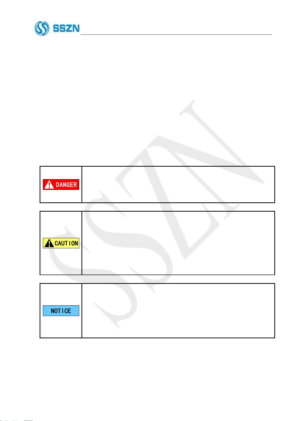
2.1.1 General Safety Precautions
Do not use this product for the purpose of protecting a human body or part of
a human body.
This product is not intended for use as an explosion-proof product. Do not use
this product in a hazardous location and/or potentially explosive atmosphere.
At startup and during operation, be sure to monitor the functions and
performance of the SR Series 3D Camera.
We recommend that you take substantial safety measures to avoid any damage
in the event of malfunction of the product.
Do not allow the temperature to change sharply around the SR Series 3D
Camera, including the accessories. Otherwise, condensation may lead to
malfunction.
Do not attempt to open or modify the SR Series or use it in any way other than
as described in the specifications. If the SR Series 3D Camera is modified or
used other than as described, the warranty will be voided.
When the SR Series is used in combination with other devices, functions and
performance may be degraded, depending on the operating conditions and
surrounding environment.
CNSSZN Technology Ltd.
www.cnsszn.com
13/63
Hardware Manual of SR Series © 2021 SSZN All Right Reserved
2.1.2 Safety Precautions on Laser Product
If the product is not used, controlled or adjusted as specified herein, or
operations steps are not performed as specified herein, hazardous radiation
exposure may be caused. Follow the instructions mentioned in this manual.
Otherwise, injury to the human body (eyes and skin) may be resulted.
Precautions on Class 2M Laser Product
Do not stare into the direct laser beam or specularly reflected beam.
Do not direct the beam at other people or into areas where other people
might be present.
Be careful of the path of the laser beam. If there is a possibility that the
operator may be exposed to the specular or diffuse reflections, block the
beam by installing a protective cover.
Install this product in such a way that the path of the laser beam is not as
the same height as that of human eyes.
Viewing the laser output with certain optical instruments (for example,
eye loupes, magnifiers and microscopes) within a distance of 100 mm may
pose an eye hazard.
Precautions on Class 2 Laser Product
Do not stare into the direct laser beam or specularly reflected beam.
Do not direct the beam at people or into areas where people might be
present.
Be careful of the path of the laser beam. If there is a possibility that the
operator may be exposed to the specular or diffuse reflections, block the
beam by installing a protective cover.
Install this product in such a way that the path of the laser beam is not as
the same height as that of human eye.
Do not disassemble this product. Laser emission from this product is not
automatically stopped when it is disassembled.
CNSSZN Technology Ltd.
www.cnsszn.com
14/63
Hardware Manual of SR Series © 2021 SSZN All Right Reserved
2.2 Important Instructions
Observe the following cautions to prevent malfunction of the SR Series 3D Camera and
to ensure that it is used properly.
2.2.1 Precautions for Use
Use this instrument at the correct supply voltage. Failure to do so may cause
fire, electric shock, or a product damage.
Do not disassemble or modify this instrument. Doing so may cause fire and
electric shock.
Attach the camera to a metal plate for use. The camera surface temperature may
increase, which may cause burn injuries.

CNSSZN Technology Ltd.
www.cnsszn.com
15/63
Hardware Manual of SR Series © 2021 SSZN All Right Reserved
The power of the controller and peripherals connected to this controller must
be turned off when the camera cable is plugged or unplugged. Failure to do so
may cause product damage.
Do not connect or disconnect the display unit and the controller while the
power is on. Failure to do so may cause a product damage.
Do not turn off this product while this product is writing data to memory, for
example, when settings are being modified. Failure to do so may cause loss of a
part of or all of the setting data.
The USB connector and a part of the input/output terminals are not insulated
from the DC24V (-) terminal. Exercise caution not to produce a potential
difference between the non-insulated terminals due to a positive grounding or a
potential difference between devices. Otherwise, it may cause a malfunction in
the controller or a malfunction in the connected computer or other external
device.
We recommend backing up the settings with EdgeImaging in case there are
problems with the product.
A change in the ambient temperature may cause the measurement to fluctuate.
Be sure to keep the temperature stabilized. When the ambient temperature
changes by 10 ℃, the product takes 60 minutes to achieve uniform internal
temperature distribution.
Wait approximately 30 minutes after the power is turned on before using the
SR Series 3D Camera. Otherwise, the measured value may gradually fluctuate
because the circuit is not immediately stable after the power is turned on.
Do not operate this product near lighting fixtures. If the product must be used
in such a location, install a light shielding board or similar device so that the
light will not affect the measurement.
When the target is vibrating, the measured value may fluctuate. In this case,
increase the averaging of the profiles and the measurement averaging to
achieve a more accurate value.
Due to the slow flow of air, the measured values may be deviant. In this case,
take the following countermeasures.
Project the measurement area with a protective cover.
Agitate the air between the measurement point and the workpiece more
strongly with a fan.

CNSSZN Technology Ltd.
www.cnsszn.com
16/63
Hardware Manual of SR Series © 2021 SSZN All Right Reserved
2.2.2 Precautions in Emergency
Turn the power off immediately in the following cases. Using the product in an
abnormal condition could cause fire, electric shock, or accident.
Contact the SSZN office for repair.
If liquid, including water or chemicals, or debris enters the controller.
If the product is dropped or the case is damaged.
If abnormal smoke or odor is present.
2.2.3 Precautions on Installation
To use this instrument correctly and safely, avoid installing it in the following
locations. Installation in such locations may cause malfunction.
Locations that are humid, dusty or poorly ventilated.
Locations where the temperature is high, such as those exposed to direct
sunlight.
Locations where there are flammable or corrosive gases.
Locations where the product may be subject to vibration or impact.
Locations where water, oil, or chemicals may splash onto the product.
Locations that are prone to static electricity.
Installing the product in the vicinity of an electrical noise source such as a
power source and high-voltage line could cause malfunction and product
damage due to noise. Take preventive actions such as using noise filters,
separating cables, and insulating the controller and the camera. Use
single-conductor shielded cable as the analog output cable.
In the following cases, foreign matters such as dust and debris or water and oil
could cause differences in the measurement values.
Adhesion on the protective glass: Blow the dirt off with clean air. If dirt
persists, wipe the glass surface gently using a soft cloth moistened with alcohol.
Adhesion on the surface of the measuring target: Blow the dirt off with clean
air or wipe it off.
Intrusion of floating or sprinkled dust or dirt into the light-axis range: In this
case, take corrective action with a protective cover or air purge.

CNSSZN Technology Ltd.
www.cnsszn.com
17/63
Hardware Manual of SR Series © 2021 SSZN All Right Reserved
2.2.4 Precautions in Storing
Do not wipe the product with a wet wipe, benzine, or thinner. Doing so could change
the color or shape of the product. If the product has a large amount of dirt on it,
wipe it off with a cloth moistened with a mild detergent, then wipe with a soft dry
cloth.
CNSSZN Technology Ltd.
www.cnsszn.com
18/63
Hardware Manual of SR Series © 2021 SSZN All Right Reserved
3 Quick Start
3.1 Checking the Package
Before opening the package, please check whether the model of products marked on the package is consistent
with the products that you ordered. After opening the package, first, please put on the antistatic gloves, and then
carefully check whether the accessories are complete according to the packing list or the order contract. Check
whether there is a mechanical damage to the surface of the camera or the controller, if the surface of camera is
damaged, or the products are not accord to the packing list or the order contract, please do not use it, and
quickly contact with SSZN.
You can download the Hardware Manual of SR Series 3D Camera from SSZN official home page website at
http://www.cnsszn.com.
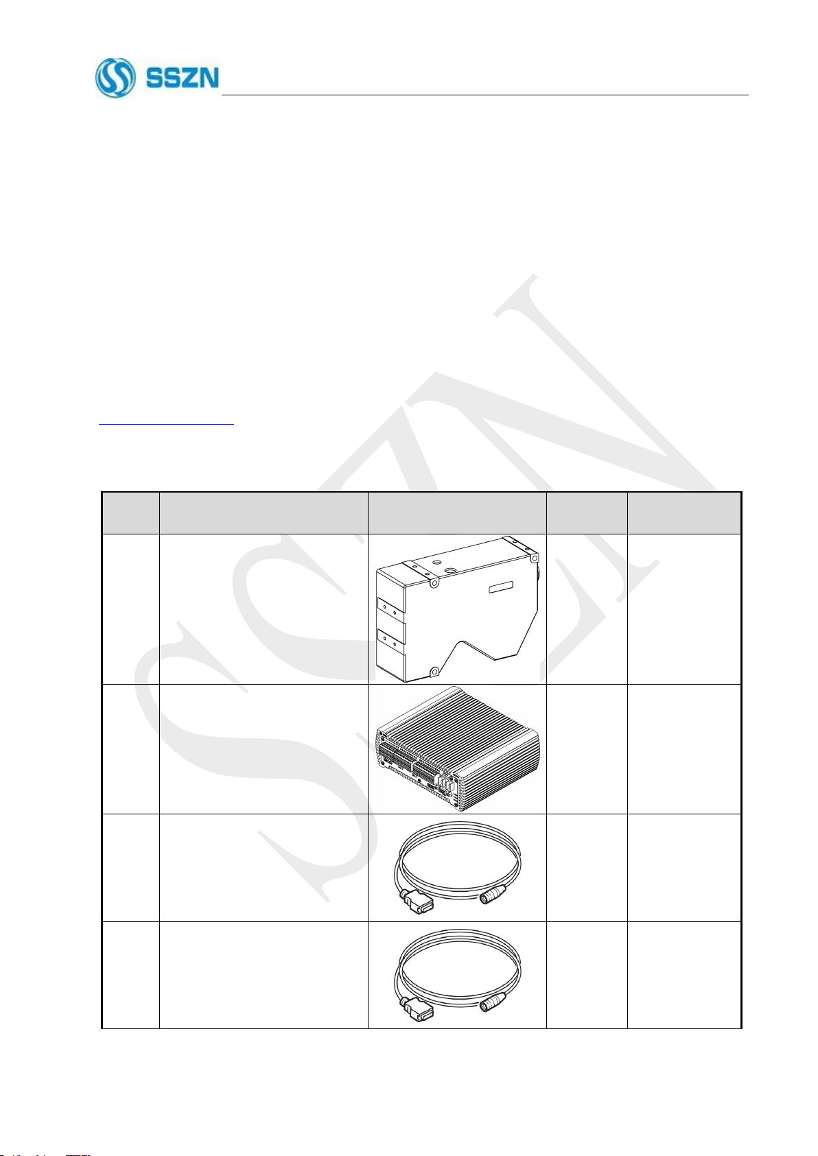
Table 3- 1 Packing List
Item
Name and Specification
Diagram
Quantity
Remark
1
SR Series 3D Camera
1
2
Controller, SR7001
1
s
3
Camera Cable 3 meter,
SCB-HCAM-HB1-3m
1
4
Camera Cable 10 meter,
SCB-HCAM-HB1-10m
□
Optional
Accessories
CNSSZN Technology Ltd.
www.cnsszn.com
19/63
Hardware Manual of SR Series © 2021 SSZN All Right Reserved
3.2 Environmental Requirements
Keep away from the strong electromagnetic noise source such as a high-power equipment and high-voltage
line.
Avoid sharing power source with the high-power equipment.
Avoid laying the Camera cable and the Ethernet cable in parallel with the power lines.
3.3 Preparation before Installation
Before installation, first, please prepare the following items:
Ethernet Cable (category 7 or higher or compatible with 10GBase-T)
Multimeter
Wire Stripping Plier
Wire Crimping plier
Flat Gasket, M4 x4
A set of Flathead Screwdrivers
A set of Cross Screwdrivers
A set of Hex Key Allen Wrench
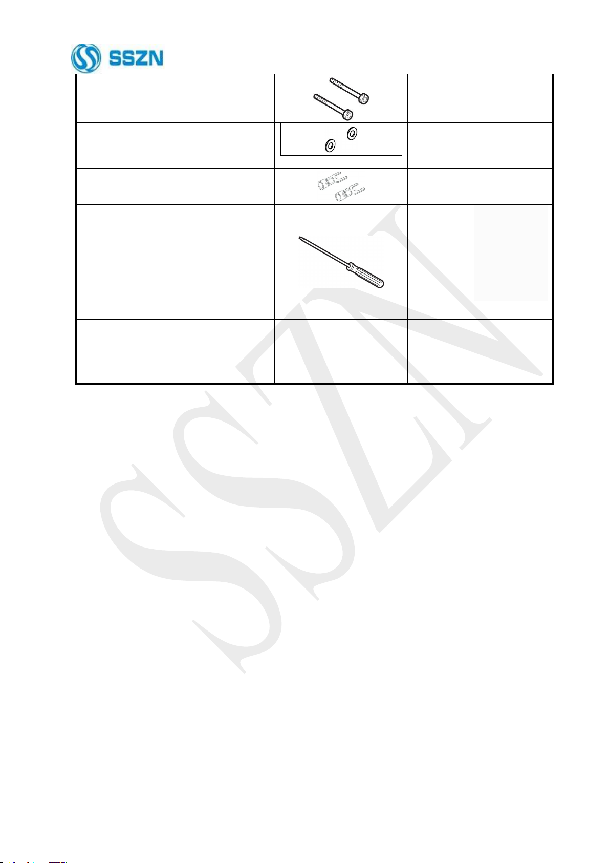
5
Hexagon socket bolts, M4x55
3
6
Flat gasket, M4
3
7
Y-type crimping terminal head
3
8
Flathead Screwdrivers
2
The large one is
used to fix the
camera cable,
The small for
terminal block
wiring
9
Quick Start Guide
1
10
Certificate
1
11
Warranty Card
1
CNSSZN Technology Ltd.
www.cnsszn.com
20/63
Hardware Manual of SR Series © 2021 SSZN All Right Reserved
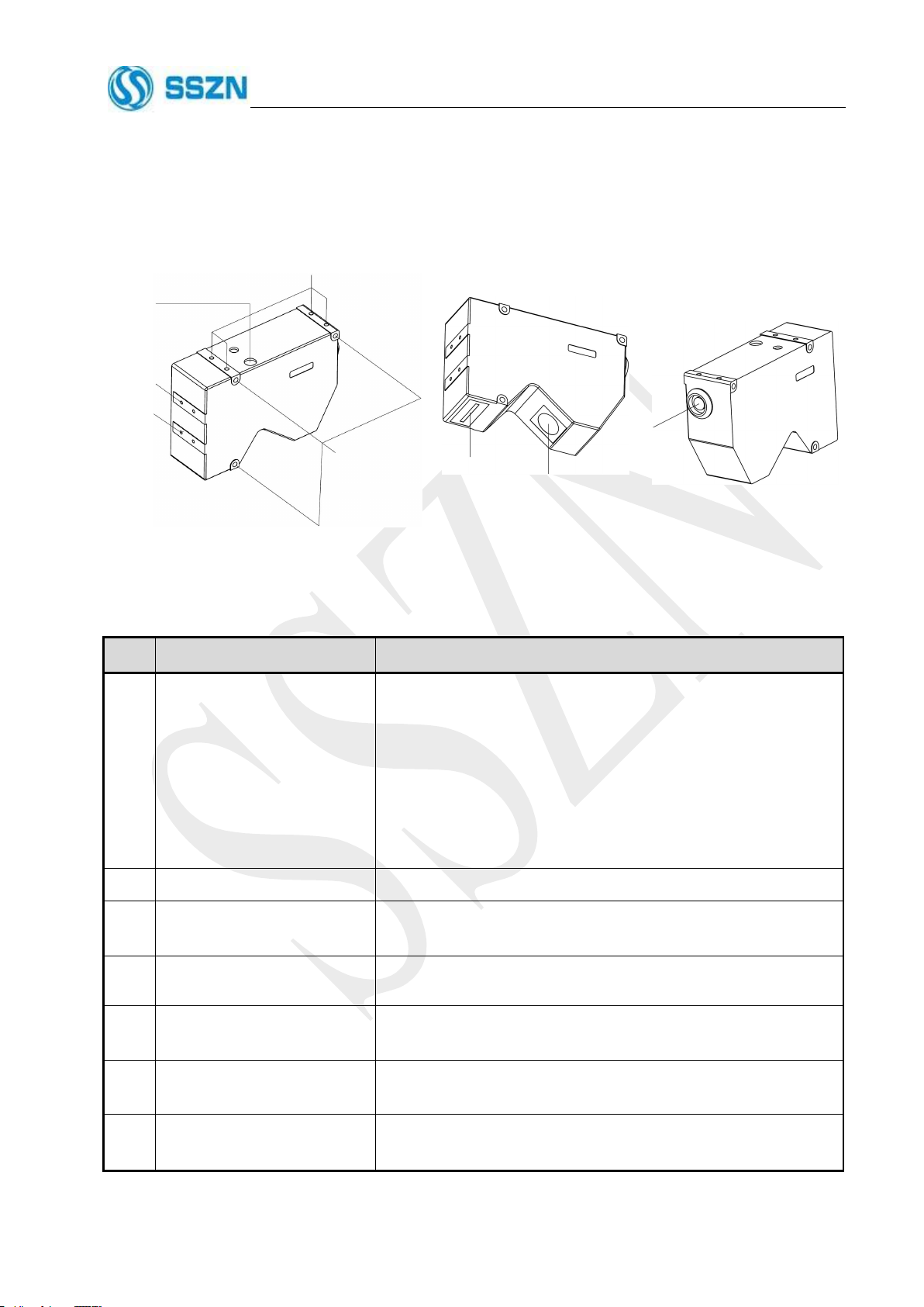
3.4 Part Names and Functions
3.4.1 Part Names and Functions of Camera
1
2
3
4
4
5
6
7
Figure 3- 1 Camera Description
Table 3- 2 Part Names and Functions of Camera
Item
Name
Description
1
Laser-emitting LED
Lights or blinks while the SR Series device is in operation, please
refer to “5.1 Description of the Camera LED”
Lights green: When the target object is around the center of the
measurement area.
Lights orange: When the target object is in the measurement area.
Blinks orange: When the target object is out of the specified
measurement area.
Lights red: When any system error occurs at the camera.
2
Special mounting holes
The screw holes can be used to mount the camera.
3
Mounting holes
Use the hexagon socket bolt (included) to affix the camera.
Please refer to “3.5.1 Mounting the Camera”
4
Mounting holes for the stray
light shield
Use the holes to mount a plate for blocking stray light. Do not use
for mounting the camera.
5
Sensor (receiver)
Receive the laser beam for measurement.
Protected by a glass cover.
6
Sensor (transmitter)
Emit the laser beam for measurement.
Protected by a glass cover.
7
Cable connector
Connected with the camera cable.
Please refer to “4.2 Connecting the controller and the Camera”.
Other manuals for SR Series
1
This manual suits for next models
19
Table of contents
Other SSZN 3D Camera manuals


