ESPROS TOFcam-635 User manual

TOFcam-635
Installation and Operation Manual
General description
The TOFcam-635 is a miniaturized and cost-optimized 3D TOF
camera. It is based on the ES ROS proprietary time-of-flight (TOF)
technology using the epc635 TOF chip. The camera controls the
illumination and the imager chip to obtain distance and grayscale
images.
The cameras are calibrated to provide accurate 3D depth images.
By using the ROS driver from ES ROS, 3D point clouds in a world
cartesian coordinate system are available.
The depth images are compensated against DRNU errors, modula-
tion errors, ambient-light, temperature and reflectivity of the scene.
Thanks to the high performance of the imager chip with the unique
ambient-light suppression, the camera can be used in many cases
under full sunlight conditions. The output of the TOFcam-635 is
depth and grayscale images – allowing a variety of new applica-
tions, e.g. for mobile robotics. This module brings you right in front
with the latest technology of 3D depth sensing. All the complex
engineering and time consuming design tasks regarding optics,
illumination and signal processing are already solved.
Features
■160 x 60 pixels (9600 pixels)
■Field of view (FOV) of 50° x 19° (h x v)
■Distance measurement ranges on white target:
Wide FOV: 0.1 ... 7.5 m, center beam (NFOV): 1.0 ... 15 m
■Measurement rate up to 50 TOF measurements per second
■Sun- and ambient-light tolerant up to 100 kLux
■Calibrated and compensated
■Temperature compensated
■Easy to use
■High speed serial interface UART 10 Mbit/s
■Low power consumption
■GUI for Windows and Mac
■ROS application for Linux
■ython library for Windows
■Software source code on request
■Customized versions possible
Applications
■Distance measurement from centimeters to a few meters
■Mobile robots, automatic vehicle guidance, collision avoidance
■Scanner for SLAM data acquisition in mobile robots
■eople and object counting, in-cabin monitoring
■Door opening, machine controlling and safeguarding, IoT
■Gesture control (man-machine-interface)
■Object classification
Figure 1: TOFcam-635 Figure 2: Wide and narrow field definition
© 2022 ES ROS hotonics Corporation
Characteristics subject to change without notice
1 / 52 Installation_and_Operation_Manual_TOFcam635-V2.0
www.espros.com

Contents
1. Before you start ............................................................................................................................................................ 4
1.1. recaution and Safety ..............................................................................................................................................................................4
1.2. Updates.....................................................................................................................................................................................................4
1.3. Important Notes........................................................................................................................................................................................4
. Abbreviations................................................................................................................................................................. 5
3. TOFcam-635 time of flight camera .............................................................................................................................. 7
3.1. System overview ......................................................................................................................................................................................7
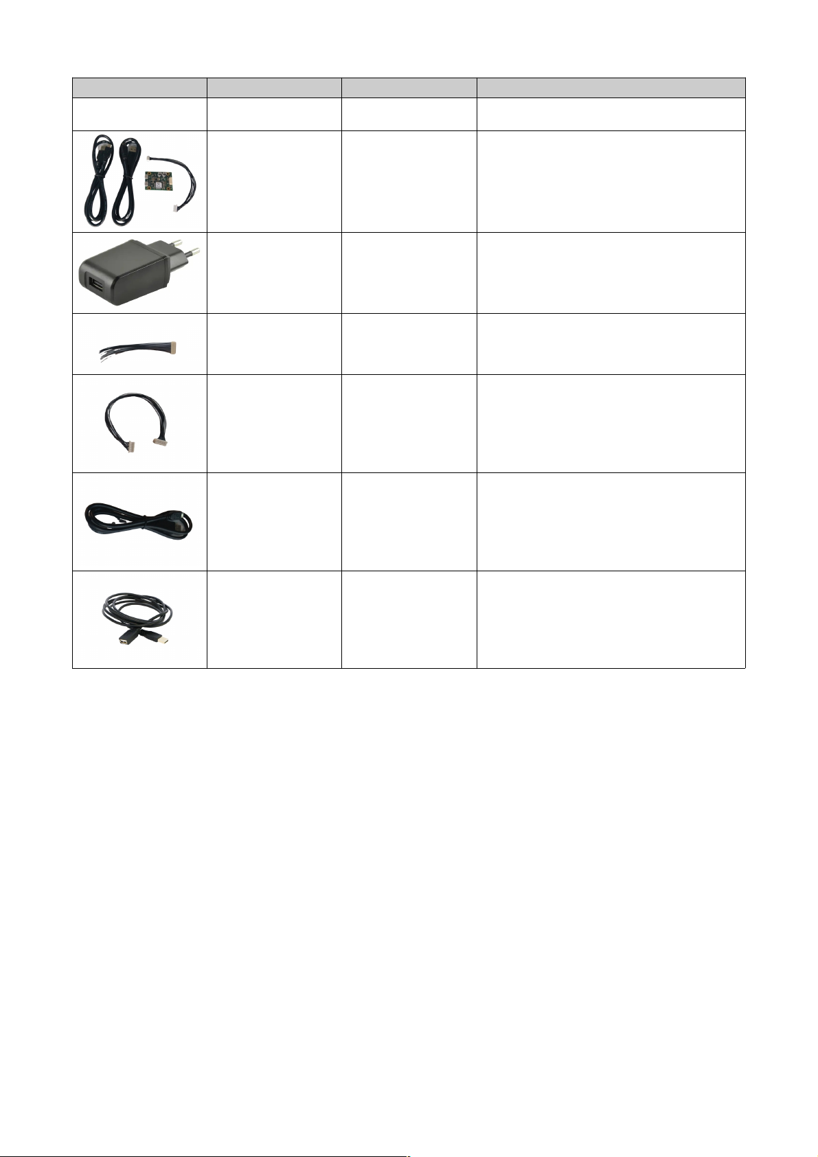
3.2. Scope of delivery .....................................................................................................................................................................................7
3.3. Ordering information ................................................................................................................................................................................8
3.4. Technical data ..........................................................................................................................................................................................9
3.5. Mechanical data .....................................................................................................................................................................................10
3.5.1. Mechanical features ...............................................................................................................................................................................10
3.5.2. Mechanical dimensions ..........................................................................................................................................................................10
3.5.3. Mounting the camera .............................................................................................................................................................................11
3.6. Camera connectors ................................................................................................................................................................................12
3.7. Interface assembly variant .....................................................................................................................................................................13
4. Start up ........................................................................................................................................................................ 13
4.1. ower up with UART ..............................................................................................................................................................................13
4.2. System setup over USB .........................................................................................................................................................................13
5. GUI ............................................................................................................................................................................... 15
5.1. GUI main window ...................................................................................................................................................................................15
5.1.1. View menu .............................................................................................................................................................................................15
5.1.2. lay menu ..............................................................................................................................................................................................18
5.1.3. Streaming files format description .........................................................................................................................................................18
5.1.4. Live image window .................................................................................................................................................................................20
5.1.5. oint cloud .............................................................................................................................................................................................20
5.1.6. Dedicated information windows .............................................................................................................................................................28
5.2. I/O Control ..............................................................................................................................................................................................29
5.3. COM port settings ..................................................................................................................................................................................30
5.4. Configurations menu ..............................................................................................................................................................................30
6. Operating the device with a ROS .............................................................................................................................. 3
6.1. ROS camera driver.................................................................................................................................................................................32
6.1.1. What is ROS?.........................................................................................................................................................................................32
6.1.2. Installation...............................................................................................................................................................................................32
6.1.3. Running the ROS driver..........................................................................................................................................................................32
6.2. ROS A I..................................................................................................................................................................................................33
6.2.1. Test environment ...................................................................................................................................................................................33
6.2.2. Start of the node.....................................................................................................................................................................................33
6.2.3. ublished topics......................................................................................................................................................................................33
6.2.4. Dynamically reconfigurable parameters.................................................................................................................................................34
7. Communication interface............................................................................................................................................ 35
7.1. Hardware interface..................................................................................................................................................................................35
7.2. Software interface...................................................................................................................................................................................35
7.3. Command format....................................................................................................................................................................................36
7.4. Response format.....................................................................................................................................................................................36
7.5. CRC checksum.......................................................................................................................................................................................36
7.6. Acknowledge ACK (response)................................................................................................................................................................37
7.7. Error handling.........................................................................................................................................................................................37
8. Command set overview............................................................................................................................................... 38
8.1. SET commands......................................................................................................................................................................................38
8.2. GET commands......................................................................................................................................................................................39
8.3. Miscellaneous commands......................................................................................................................................................................40
8.4. Factory maintenance commands............................................................................................................................................................41
9. SET commands ........................................................................................................................................................... 4
9.1. SET_MOD_CHANNEL [0x0E] .............................................................................................................................................................42
9.2. SET_INT_TIME_DIST [0x00] ..............................................................................................................................................................43
9.3. SET_INT_TIME_GS [0x01] .................................................................................................................................................................43
9.4. SET_O ERATION_MODE [0x04] .......................................................................................................................................................44
9.5. SET_HDR [0x0D] .................................................................................................................................................................................44
9.6. SET_ROI [0x02] ...................................................................................................................................................................................45
9.7. SET_TEM ORAL_FILTER_WFOV [0x07] ..........................................................................................................................................45
9.8. SET_TEM ORAL_FILTER_NFOV [0x0F] ..........................................................................................................................................45
9.9. SET_AVERAGE_FILTER [0x0A] .........................................................................................................................................................46
9.10. SET_MEDIAN_FILTER [0x0B] ............................................................................................................................................................46
9.11. SET_INTERFERENCE_DETECTION [0x11] ......................................................................................................................................46
© 2022 ES ROS hotonics Corporation
Characteristics subject to change without notice
2 / 52 Installation_and_Operation_Manual_TOFcam635-V2.0
www.espros.com

9.12. SET_EDGE_DETECTION [0x10]..........................................................................................................................................................47
9.13. SET_FRAME_RATE [0x0C] ................................................................................................................................................................47
9.14. SET_AM LITUDE_LIMIT [0x09] .........................................................................................................................................................47
9.15. STO _STREAM [0x28 ] ......................................................................................................................................................................47
9.16. SET_COM ENSATION [0x55] ............................................................................................................................................................47
9.17. SET_ILLUMINATION_ OWER [0x6C] ...............................................................................................................................................48
9.18. SET_DLL_STE [0x06] .......................................................................................................................................................................48
10. GET commands........................................................................................................................................................... 49
10.1. Acquisition modes...................................................................................................................................................................................49
10.2. Acquisition data output formats..............................................................................................................................................................49
10.3. Response header....................................................................................................................................................................................50
10.4. Warm-up.................................................................................................................................................................................................52
10.5. GET_DIST [0x20] .................................................................................................................................................................................53
10.6. GET_DIST_GS [0x29] .........................................................................................................................................................................53
10.7. GET_DIST_AM LITUDE [0x22] ..........................................................................................................................................................53
10.8. GET_GS [0x24] .....................................................................................................................................................................................54
10.9. GET_DCS [0x25 ] ................................................................................................................................................................................54
10.10. GET_CALIBRATION_INFO [0x57 ] .....................................................................................................................................................54
11. Miscellaneous commands.......................................................................................................................................... 55
11.1. SET_OUT UT [0x51] ..........................................................................................................................................................................55
11.2. GET_IN UT [0x52] ..............................................................................................................................................................................55
11.3. GET_TEM ERATURE [0x4A] .............................................................................................................................................................55
11.4. GET_TOFCOS_VERSION [0x49] .......................................................................................................................................................55
11.5. GET_CHI _INFORMATION [0x48] .....................................................................................................................................................55
11.6. GET_ ROD_DATE [0x50] ...................................................................................................................................................................56
11.7. IDENTIFY [0x47] ..................................................................................................................................................................................56
11.8. GET_ERROR [0x53] ............................................................................................................................................................................56
1 . Factory maintenance commands............................................................................................................................... 57
12.1. CALIBRATE_DRNU [0x41] ..................................................................................................................................................................57
12.2. GET_CALIBRATION [0x43] .................................................................................................................................................................57
12.3. JUM _TO_BOOTLOADER [0x44] ......................................................................................................................................................57
12.4. U DATE_TOFCOS [0x45] ..................................................................................................................................................................58
12.5. WRITE_CALIBRATION_DATA [0x4B] ................................................................................................................................................58
12.6. SET_MOD_FREQUENCY [0x05] ........................................................................................................................................................58
12.7. SET_BINNING [0x03] ..........................................................................................................................................................................58
13. Update camera operating system TOFCOS.............................................................................................................. 59
14. Maintenance and disposal.......................................................................................................................................... 60
14.1. Maintenance............................................................................................................................................................................................60
14.2. Disposal..................................................................................................................................................................................................60
15. Addendum ................................................................................................................................................................... 60
15.1. Related documents ................................................................................................................................................................................60
15.2. Links .......................................................................................................................................................................................................60
15.3. Licenses .................................................................................................................................................................................................60
16. IMPORTANT NOTICE................................................................................................................................................... 61
© 2022 ES ROS hotonics Corporation
Characteristics subject to change without notice
3 / 52 Installation_and_Operation_Manual_TOFcam635-V2.0
www.espros.com

1. Before you start
1.1. Precaution and Safety
This product is eye safe according to IEC62471-2013.
The camera module is an electronic device. Handle it with the necessary ESD precaution.
Over-voltage: Use only a power supply which correspond to the datasheet of the camera to avoid damage of the device
or cause danger for humans.
Cable-tripping: lace or mount the sensor on solid ground or fix it correctly on a solid support. lace cables carefully.
Falling devices can be damaged or harm persons.
The sensor comes with its own calibrated TOFCOS. Do not alter the TOFCOS without obeying the instructions herein.
Take care that the lens surfaces of the camera. Never use any solvents, cleaners or mechanically abrasive towels or
high pressure water to clean the sensor.
Operate the device in compliance with the local EMC regulations.
This camera is not a safety device. It may not be used in safety applications, explosive atmospheres or in radioactive
environment, except the user implements the required safety measures, e.g. by redundancy. However, the sole respon-
sibility for the safety of the application is by the user.
LIMITED WARRANTY - LOSS OF WARRANTY
This camera should only be installed and used by authorized persons. All instructions in this datasheet and in the
related documents shall be followed and fully complied with. In addition, the installer and user is required to comply with
all local laws and regulations. The installer and user is fully responsible for the safe use and operation of the system. It
is the sole responsibility of the installer and the user to ensure that this product is used according to all applicable codes
and standards, in order to ensure safe operation of the whole application. Any alteration to the devices by the buyer,
installer or user may result in device damage or unsafe operating conditions. ES ROS hotonics AG is not responsible
for any liability or warranty claim which results from such manipulation or disregarding of given operating instructions.
ES ROS hotonics AG is an ISO 9001: 2015 certified company.
This product is according to European Union standards and free of hazardous substances.
1. . Updates
ESPROS Photonics is constantly striving to provide comprehensive and correct product information. Therefore, please check
ESPROS' website regularly for updated versions of datasheets and documentations: www.espros.com
Download the latest Flyer TOFcam-635.
Download the latest Installation and Operation Manual of the TOFcam-635.
Download and use the latest TOFCAM635_SW_ ackage.
If there are any questions, please contact your ES ROS sales office or send an email to sales@espros.com.
1.3. Important Notes
Colored marking in text means “under consideration” and refers to not yet applicable or verified information.
Values and/or information are either estimates or show the applicable principle only.
© 2022 ES ROS hotonics Corporation
Characteristics subject to change without notice
4 / 52 Installation_and_Operation_Manual_TOFcam635-V2.0
www.espros.com

. Abbreviations
Designator Description
3D Three dimensional
ACK Acknowledged
A I Application program interface
A/D Analog to digital
Binning Summation of a defined number of pixels. Binning can be done in the charge (analog) or in the digital domain
CMD Command
C U Central rocessing Unit
CRC Cyclic redundancy check (checksum)
cwTOF Continuous wave modulated time of flight
DCS Differential correlation sample
DLL Delay locked loop, controllable delay line
DRNU Distance response non-uniformity: Distance error from pixel to pixel with a target at the same distance
EMC Electromagnetic compatibility
EMI Electromagnetic interference
ESD Electrostatic discharge
FOV Field of view
fps Frame rate, number of images per second
Frame One image
GND Ground terminal, negative supply voltage
GS Grayscale
GUI Graphical user interface
HDR High dynamic range
ID Identifier
IN Input terminal which is used to sense a high or low voltage
ISO International organization for standardization
JEDEC Joint electron device engineering council
LED Light emitting diode used to illuminate the scenery or as indicator
LSB Least significant bit / byte
LVTTL Low voltage transistor transistor logic
MCU Microcontroller Unit
MSB Most significant bit / byte
NACK Not acknowledged
NFOV Narrow field of view
OUT Output terminal which is can be set to high or low voltage
RMS Root mean square
RoHS Restriction of hazardous substances
ROI Region of interest in the pixel-field
ROS Robot operating system
RX Receive terminal, data in
SLAM Simultaneous localization and mapping
SW Software
TBD / tbd To be defined, information not yet available or not valid
TOF Time of flight
TOFCOS Time of flight camera operating system, firmware in the camera
© 2022 ES ROS hotonics Corporation
Characteristics subject to change without notice
5 / 52 Installation_and_Operation_Manual_TOFcam635-V2.0
www.espros.com

Designator Description
TTL Transistor transistor logic
TX Transmit terminal, data out
UART Universal asynchronous receiver transmitter
USB Universal Serial Bus
VDD ositive supply voltage
WFOV Wide field of view
Table 1: List of abbreviations used in this document
© 2022 ES ROS hotonics Corporation
Characteristics subject to change without notice
6 / 52 Installation_and_Operation_Manual_TOFcam635-V2.0
www.espros.com

3. TOFcam-635 time of flight camera
3.1. System overview
The TOFcam-635 is a miniaturized and cost-optimized 3D TOF camera based on the ES ROS epc635 cwTOF imager chip with an
integrated SLAM feature:
•5VDC power supply input
•General purpose I/O connector
•STM32 ARM Cortex MCU
•The micro controller board communicates with the epc635 chip carrier board through an ultrafast TCMI serial interface.
•High performance TOF lens
•NIR band pass filter, AR coatings and stray-light suppression for optimal optical performance
•LED illumination adopted to the specific field of view
•LED illumination for narrow spot SLAM feature
•TOF camera operating system (TOFCOS) for camera control, distance calculation and filtering
•Communication by UART (standard) or USB (optional adapter required)
•Application programming interface (A I) for further processing is available. It opens the world for point cloud computing, using
open source tools or creating own customer applications.
•ROS device drivers for Linux available, Windows, Mac and Linux GUI available
3. . Scope of delivery
Pieces Part Name Picture
1 Time of Flight Camera TOFcam-635 consisting of:
–Designer housing with 2 IR windows
–Aluminum base plate and heat sink
–Receiver optic
–Illumination cpl.
–C U electronics
–Interfaces
1 “Fix clip” Aluminum mounting plate
2 Self tapping screws for camera mount
1 Software package containing GUI, ROS, ython A I and current
Firmware. Available on the ES ROS download page.
1 Documentation
(useful additional information available on the Espros download page )
Table 2: Scope of delivery
© 2022 ES ROS hotonics Corporation
Characteristics subject to change without notice
7 / 52 Installation_and_Operation_Manual_TOFcam635-V2.0
www.espros.com

3.3. Ordering information
Picture Part No. Name Description
100 531 TOFcam-635 FoV 51° x 20°, 7.5m operating range (WFOW)
FoV 5° x 5°, 15m operating range (NFOW)
100 539 Adapter Kit UART to USB For TOFcam-635
- Adapter
- Cable 2 x 10 pin F-F, L = 150mm
- 2 Cables USB A – micro USB
100 610 ower supply 5VDC Input 90 … 260V
DC output 5V, 2A
USB A receptacle
100 516 Cable 10 pin, F, 75mm
JST 1.0mm, 28 AWG
Cable to connect a TOFcam-635 to a host
100 566 Cable 10 pin, F-F, 150mm
JST 1.0mm, 28 AWG
Cable to connect a TOFcam-635 to the UART to USB
adapter (included in 100 539)
300 473 Cable USB A to Micro
USB
To connect the UART to USB adapter to a power
supply and to a computer (2 x included in 100 539)
100 440 USB A extension cable,
M-F, 2m
Table 3: Order information for cameras and accessories
© 2022 ES ROS hotonics Corporation
Characteristics subject to change without notice
8 / 52 Installation_and_Operation_Manual_TOFcam635-V2.0
www.espros.com

3.4. Technical data
All characteristics are at typical operational ratings, TA = +25ºC, VDD / VDDLED = 5V, object reflectivity 90%, unless otherwise stated.
Parameter Description Conditions Min. Type Max. Units Comments
VDD Main supply voltage Ripple 1 < 50 mVpp 4.75 5.0 5.25 V
VDDLED LED supply voltage Ripple 1 < 200 mVpp 4.75 5 5.25 V
IDD Main supply current Acquisition 140 mA
Idle 100 mA
IDDLED LED supply current Acquisition 200 / 925 mA RMS / eak, @ VDDLED 5V,
30fps
Idle 10 mA @ VDDLED 5V
λ Operating wavelength 850 nm
RESIMAGE Image resolution 160 x 60 ixel
FOV Field of view WFOV 50 x 19 ° 160x60 pixel
NFOV 5 x 5 ° 8x8 NFOV pixel
D Operating range WFOV 0.10 7.5 m Depends on integration time
NFOV 1 15 m
DUnabiguity Unambiguity range 2WFOV 7.5 m
NFOV 15.0 m
Acc Accuracy WFOV 0.1 … 2.0 m ± 4 cm Mean of 100 samples
WFOV 2.0 … 7.5 m ± 2 %
NFOV 3.0 ... 15.0 m ± 2 %
DNOISE Distance noise (1σ value) WFOV 0.1 mm Amplitude 100 ... 1'900 LSB,
Kalman Filter k = 10 and
threshold t = 300 mm,
ambient-light less than
10 kLux on target
NFOV 0.1 mm
tINT Integration time selectable 1 1000 µs Default: 125µs
tCYCLE Measurement cycle time GET_DIST
GET_DIST_AM LITUDE
50
72
ms
ms
@tINT = 125µs, single
measurement, including data
transmission
fMOD Modulation frequency WFOV 19.20 20.00 20.70 MHz Refer to Chapters 9.1 and
5.1.1
NFOV 9.60 10.00 10.35 MHz
tWR_U ower up time until acceptance of commands 1.5 s
tWARM_U Warm-up time until output data is in tolerance Refer to Chapter 10.4
RESDISTANCE Distance measurement resolution 1 mm/LSB Refer to Chapter 10.
ΦAL Ambient-light suppression 100 kLux Indirect, on target
Ee EAK eak illumination irradiance 372 W/m2With 200mm distance to the
front surface of the camera
Ee AVG Average illumination irradiance 108 W/m2With 200mm distance to the
front surface of the camera
VOUT OUT1 / OUT2 voltage drive capability 36 V Refer to Figure 9
IOUT OUT1 / OUT2 current sink capability 50 mA Over-current protected
VIN IN input voltage logic low 0 0.8 V Input resistance 100kΩ,
refer to Figure 8
logic high 3.0 30 V
TAAmbient temperature range -20 60 °C Operation and storage
RH Relative humidity 15 90 % Non-condensing
W Weight 43 g Without cable
ESD Electrostatic discharge rating JEDEC HBM class 1C (1kV to < 2kV) Human body model
EMC / EMI EMC emission EN 61000-6-3:2011, EN 61000-6-2:2005
Eye safety IEC62471:2013
Table 4: Technical data
Notes:
1Min. and Max. voltage values include noise and ripple voltage
2The camera uses the continuous-wave TOF phase-shift measurement technique with a modulation frequency of 10MHz (NFOV) and
20MHz (WFOV). This leads to unambiguity distances of 15m and 7.5m respectively. Highly reflective objects outside of the effective
operating range of 15 / 7.5m will appear closer due to the wrap-around of the modulation period.
© 2022 ES ROS hotonics Corporation
Characteristics subject to change without notice
9 / 52 Installation_and_Operation_Manual_TOFcam635-V2.0
www.espros.com

3.5. Mechanical data
3.5.1. Mechanical features
The distance measurement starts from the front window of the housing with distance value 0mm. The mounting plate contains 2 holes
with a diameter of 3.6mm for mounting. Use only these mounting points. Use the screws included in the scope of delivery. A maximum
height of 2.8mm is allowed for the screw head. Because the mounting plate is also a heat sink for the illumination LEDs, it should not be
covered by thermal insulating material. Free air flow shall be provided at any time in order to avoid excessive heat of the camera. The
camera temperature can be monitored by reading the temperature with the command GET_TEM ERATURE (refer to Chapter 11.3) or
using the GUI respectively (refer to Figure 25)
3.5. . Mechanical dimensions
© 2022 ES ROS hotonics Corporation
Characteristics subject to change without notice
10 / 52 Installation_and_Operation_Manual_TOFcam635-V2.0
www.espros.com
Figure 4: Mechanical dimensions
Figure 3: Mechanical features
Zero Distance
(camera lens window)
Base plate
Connector
Indicator
LEDs
Cover
Illumination window
X axis
Y axis
Distance axis (spheric)
Mounting plate

3.5.3. Mounting the camera
3.6. Camera connectors
Connector type: JST SM10B-SRSS-TB
Matching plug: JST SHR-10V-S-B or JST SHR-10V-S
Accessory: A cable with one side plug and other side with cable leads is available. Refer to Chapter 3.3.
© 2022 ES ROS hotonics Corporation
Characteristics subject to change without notice
11 / 52 Installation_and_Operation_Manual_TOFcam635-V2.0
www.espros.com
Figure 5: Mounting and dismounting the TOFcam-635
Clip the camera onto the mounting plate
Figure 6: Camera connectors
Sensor connector
TOFcam-635
F-F cable
Micro-USB connector “ WR”
to power supply 5VDC, 2A
UART to USB adapter
Micro-USB connector
“COM” to computer

Make sure to use the right plug and insert it properly to avoid damage of the device connector!
No. Name Function Comments
1 VDD VDD: +5V Stable and free of noise power supply for the imager section.
Decouple from pin 8/10.
2 GND Negative supply terminal Short with pin 9.
3 IN3 OUT1 Open-drain output, refer to Chapters 11.1, SET_OUT UT [0x51] , 5.2,
SET_OUT UT [0x51] and Figure 9.
4 IN4 OUT2
5 IN5 IN Digital input, refer to Chapters 11.2, GET_IN UT [0x52] and 5.2, SET_OUT UT
[0x51] .
6 UART_TX Data output Tx Data interface, refer to Chapter 7.
7 UART_RX Data input Rx
8 VDDLED VDDLED: +5V Supply pin for illumination circuitry. Short with pin 10.
9 GND Negative supply terminal Short with pin 2.
10 VDDLED VDDLED: +5V Supply pin for illumination circuitry. Short with pin 8.
Table 5: in table
GND
TOFcam-635
RI 100k
+5V
IN LVTTL 3.3V
GND
TOFcam-635
OUT1
OUT2
DLRL
VL
VL: Supply voltage for the load
RL: Load
DL: rotection diode for inductive loads
IL ≤ 50 mA
Figure 8: Input pin IN Figure 9: Output pins OUT1 and OUT2
3.7. Interface assembly variant
As an assembly variant it would be possible to replace the UART by an RS-485 interface. The connector according to Figure 7 and the
pinning according to Table 5 keeps the same.
For additional information please contact your ES ROS sales office or send an email to sales@espros.com.
© 2022 ES ROS hotonics Corporation
Characteristics subject to change without notice
12 / 52 Installation_and_Operation_Manual_TOFcam635-V2.0
www.espros.com
Figure 7: Interface view
in 1 in 10
Error
LED
Status
LED

4. Start up
4.1. Power up with UART
Apply power on VDD and VDDLED. The sequence does not matter. The device notifies the power-up with a short red LED flash (Error
LED). It is ready to operate as soon as the green status LED is on. Refer to Figure 7.
Error cases:
■Red error LED periodically short flashing: Firmware not or not correctly downloaded. Download the firmware with the GUI of TOFcam-
635 or with the bootloader (refer to Chapter Fehler: Referenz nicht gefunden and 13).
■Red error LED slow flashing (0.5Hz), green LED off: Error during boot-up. Switch power off/on again.
■Red error LED stays on: Error during operation. Read-out the error number or fix the problem which caused the error.
■Red error LED fast flashing (2Hz): FW-update
■If the error remains, contact your sales responsible.
Make sure that the power supply has the correct voltage and is capable to deliver the required current. lease note that there is a
surge current draw by the camera during power up. Also during image acquisition, pulse currents are drawn by the camera. A
voltage drop due to surge currents shall be avoided by placing a big enough block capacitor nearby the power supply terminals.
4. . System setup over USB
Using the optional UART to USB adapter allows a direct connection of the camera to a computer using the micro USB port indicated with
“COM”. To properly drive the camera the adapter needs an additional connection to an external 5VDC power supply with minimum 2A
using the micro USB port indicated with “ WR”.
The TOFcam-635 runs at 10 Mbit/s on the UART interface. Means, the USB adapter has to run this baud rate also on his UART port to
communicate with the camera. Thus, the TOFcam-635 GUI sets automatically host's corresponding COM ort to 10 Mbit/s.
1. Connect the TOFcam-635 to plug J2 of the USB adapter (TOFcam-635). Refer to Figure 10.
2. Connect a USB power supply (min. 2.0 A) to the plug J1 of the USB adapter ( ower Supply +5V / 2.0A). ower consumption depends
on the frame rate, so in most cases you can use also a 2nd powerful USB port from the computer (e.g. USB 3.0 high-power: >0.9A) or a
battery bank with USB port.
3. Connect your host computer to the plug J3 of the USB adapter (Host communication USB 2.0).
4. Check if all 3 LEDs are on. Refer to Figure 10:
•LED 5V illumination ok: ON when both USB ports are connected.
•LED 5V C U ok: ON when host communication USB is connected.
•LED Communication: ON when host communication USB is connected and no communication,
BLINKING when communication is in progress.
5. The device TOFcam-635 is recognized on the host as “STMicroelectronics Virtual COM ort”, automatically.
6. The TOFcam-635 is now ready to use.
© 2022 ES ROS hotonics Corporation
Characteristics subject to change without notice
13 / 52 Installation_and_Operation_Manual_TOFcam635-V2.0
www.espros.com
Figure 10: Cable connections (blue) and status LEDs (green)
TOF>cam 635
Power supply
+5V / 2.0A
Host
commun cat on
USB 2.0
5V llum nat on ok
5V CPU ok
Commun cat on

5. GUI
First, before installation of a new software release, read the README and CHANGELOG files of the download package to get latest
product information.
5.1. GUI main window
After starting the “TOFCAM635_GUI” application, the control window of the GUI appears. The software connects automatically to the
device if a camera is physically connected to the computer. The connection is indicated in the status indicator line in the footer of the
control window, the header shows the GUI version in use, the current firmware installed on the camera as well as the wafer and chip ID of
the epc635 imager. The menu selection on the left side bar allows a user to step into the GUI control options.
A) Camera type, GUI version, Firmware version, Chip-/Wafer-ID of the epc635 in the connected camera
B) Connection status:
C) Menu tab
Viewer Chapter 5.1.1
layer Chapter 5.1.2
IoControls Chapter 5.2
COM ort Chapter 5.3
Save/Load Chapter 5.4
D) Controls for the selected menu tab
5.1.1. View menu
The View menu allows to control the camera and the camera output. Distance, amplitude and gray-scale images, DCS (raw data) or point
clouds can be captured, streamed or recorded. Detailed information about pixel groups or one single pixel can be illustrated. For the whole
GUI there are helpful tooltips available. These tooltips pop-up by moving the cursor either to the corresponding text (refer to Figure 13).
© 2022 ES ROS hotonics Corporation
Characteristics subject to change without notice
14 / 52 Installation_and_Operation_Manual_TOFcam635-V2.0
www.espros.com
Figure 11: Sections of the GUI main screen
A
B
C
D

•“ icture“ and “Start“ open the “Image“ window according to the selection in the “Image Type” drop-down menu. lease see
Chapter 5.1.4 to read the details about the live image window. The “ icture“ button acquires one single frame while the “Start“
button starts a live stream. It changes its look to “Stop“ which allows terminating the streaming.
•The “Record“ function allows to save picture data (one picture per push on the “ icture“ button) or live stream (from “Start“ to
“Stop“ command each). On computers with low performance it might be helpful to enable the “Don't display” function to use all
resources for recording the live stream. The recorded data contains all values according to the selected “Image Type“.
•The “Info”, “Scope” and “Header” check boxes open additional windows with dedicated information. You will find additional
description about these functions in Chapter 5.1.6.
•In the “Mode” drop-down menu the acquisition mode is selected:
◦Wide Field data acquires with 20 MHz modulation frequency the full WFOW with 160 x 60 pixels if no additional region of
interest (ROI) was selected. The wide field illumination is active.
◦Narrow field data acquires with 10 MHz modulation frequency the 8 x 8 center pixels only with active narrow beam illumina -
tion.
◦Spot data acquires one single distance value out of the acquired 8 x 8 center pixels
◦In binning modes a 2 x 2 binning is applied to the 8 x 8 center pixels.
•“Modulation channel” selection allows a shift of the modulation frequency from the main (default) modulation frequency. Multiple
cameras operating in the same scenery (full or partially) with the same modulation frequency will interfere each other which
leads to sporadically wrong distance information. This can be eliminated if the cameras do not use the same modulation
frequency or channel respectively.
•“Interference detect” marks all interfered pixels within the set level. The “use last value” allows to overwrite interfered pixels with
the distance and amplitude values out of last valid acquisition.
•With the “Frame rate limit” a specific frame rate can be set. This frame rate needs to be below the maximum possible frame rate
at a specific camera setting.
•The “Automatic integration time” controls the integration time automatically depending on reflective objects in the illuminated
scenery.
© 2022 ES ROS hotonics Corporation
Characteristics subject to change without notice
15 / 52 Installation_and_Operation_Manual_TOFcam635-V2.0
www.espros.com
Figure 12: Camera controls

•“HDR off“ let's the camera operate with one integration time only.
•“HDR spatial“ operates all odd rows of the imager with the “Integration Time 3D low“ value and all even rows with the “Integra-
tion Time 3D medium“ value. This operation is only enabled for Wide Field data.
•“HDR temporal“ allows using up to 3 different integration time values (integration times with zero values are ignored). In this
mode one complete image is acquired with each set integration time 3D low … high. After the acquisition of all frames, a new
image is generated from the different frames by using the most confident value (pixel by pixel). Due to multiple image acquisi -
tions, this mode reduces the frame rate.
•Integration time setting allows to define the exposure time to acquire the required Differential Correlation Samples (DCS) to
calculate the distance for each pixel.
•“Low illumination” reduces the illumination power. This allow to operate the camera with adequate integration time even if high
reflective objects are detected in very narrow distance range.
•A minimal amplitude can be set. This is the minimum received signal to provide distance. One should use low limits for object
recognition but high limits for accurate distance measurements. lease investigate the TOF theory to become familiar with the
physical context. A very helpful lecture might be the book “3D-TOF, A guideline to 3D-TOF sensors that work” by ES ROS
hotonics Corp. (author Beat De Coi et. al.).
•An “Offset” moves the zero point for distance calculation away from the calibrated origin. Refer to Chapter 3.5.1
•“Distance min“ cuts off all pixels reporting a value below this setting. In addition, the color distance minimum scale is adjusted to
this setting.
•“Distance max“ cuts off all pixels reporting a value beyond this setting. In addition, the color distance maximum scale is adjusted
to this setting.
•The color scale visualizes distance of every pixel in the viewer. Dark red represents the shortest, dark blue the farthest
distances.
•Various powerful filter functions are available with specific thresholds and filter factors. The algorithms behind are shown in
corresponding tooltips.
•The ROI (region of interest) allows to reduce the readout of the pixel field. Only pixels within the selected ROI will be acquired.
The “Default ROI” button resets the ROI to full imager size of 160 x 60 pixels.
© 2022 ES ROS hotonics Corporation
Characteristics subject to change without notice
16 / 52 Installation_and_Operation_Manual_TOFcam635-V2.0
www.espros.com
Figure 13: Tooltips example

5.1. . Play menu
The “ lay“ menu allows replaying the recorded streams. This is possible in slow motion, original speed or accelerated. A single frame can
be searched and selected and the streamed data can be converted to point clouds. This functions of the GUI can be used even if no
camera is connected.
•“ lay” replays the selected stream with the set frame rate. After changing the selection or pushing the “Stop“ button the original
frame rate of the recording is used. The “Start“ button changes its look to “ ause“ after been pushed. Selecting the “ ause“
button interrupts the playback and allows to continue from the same point.
The player can replay the recorded data only with the parameters which has been set during the recording process. This
includes also the “Image Type“ according to the “View“ menu.
•“Stop“ aborts the replay, resets the timer to zero and the frame rate to the recording frame rate.
•“Record“ streams images according to the parameters set in the “View” menu, refer to Chapter 5.1.1.
•“F S” sets the acquisition frame rate (or the replay speed respectively). This value is reset by pressing the “Stop“ button or by
changing the selected log in the list.
•“File name“ defines the file name of the log file. An “underline” character separates this name from the current calendar day
followed by a “minus” separated time stamp.
•“Folder path” defines the log file location. This path can be changed either directly in the input field or with the “Select Folder”
function.
•“Delete all logs“ will delete all logs in the selected folder. “Delete selected log“ deletes the selected log only. All deletions needs
to be confirmed by the user.
•“Convert to CD“ allows converting the recorded binary files to point cloud files which are compatible with point cloud applica -
tions such as “Cloud Compare“ or “Cloud Compare Viewer“. The converted 3D point cloud has a distance color coding or an
amplitude color coding (“Convert to CDA”).
•The slide bar in the bottom allows manual spooling of the stream forth and back.
5.1.3. Streaming files format description
Images are recorded in selected folder and consists of 2 type files:
A) index ASCII file – <file name>_<yyyymmdddd>-<hhmmss>.idx
B) binary data files – <file name>_<yyyymmdddd>-<hhmmss>-<index>.bin
Index .idx file contains binary file names in ASCII format.
Image .bin files contains image information in binary format, are using LittleEndian coding and consist of 3 parts:
1. Image header (80 bytes)
© 2022 ES ROS hotonics Corporation
Characteristics subject to change without notice
17 / 52 Installation_and_Operation_Manual_TOFcam635-V2.0
www.espros.com
Figure 14: layer controls

2. Data – ROI (width x height) * 2 or ROI (width x height) * 4 (2 bytes per pixel)
3. Additional recorder information (5 bytes )
Image header
VERSION 1 byte
FRAME_COUNTER 2 bytes
TIMESTAM 2 bytes
FIRMWARE_VERSION 4 bytes
HARDWARE_VERSION 1 byte
CHI _ID 2 bytes
WIDTH 2 bytes
HEIGHT 2 bytes
ORIGIN_X 2 bytes
ORIGIN_Y 2 bytes
CURRENT_INTEGRATION_TIME_3D_WF 2 bytes
CURRENT_INTEGRATION_TIME_3D_NF 2 bytes
CURRENT_INTEGRATION_TIME_GRAYSCALE 2 bytes
INTEGRATION_TIME_GRAYSCALE 2 bytes
INTEGRATION_TIME_0 2 bytes
INTEGRATION_TIME_1 2 bytes
INTEGRATION_TIME_2 2 bytes
INTEGRATION_TIME_3 2 bytes
INTEGRATION_TIME_4 2 bytes
INTEGRATION_TIME_5 2 bytes
INTERFERENCE_DETECTION_LEVEL 2 bytes
EDGE_DETECTION_THRESHOLD 2 bytes
AM LITUDE_LIMIT_0 2 bytes
AM LITUDE_LIMIT_1 2 bytes
AM LITUDE_LIMIT_2 2 bytes
AM LITUDE_LIMIT_3 2 bytes
AM LITUDE_LIMIT_4 2 bytes
OFFSET 2 bytes
BINNING 1 byte
DISTANCE_TEM ORAL_FILTER_FACTOR 2 bytes
DISTANCE_TEM ORAL_FILTER_THRESHOLD 2 bytes
SINGLE_VALUE_TEM ORAL_FILTER_FACTOR 2 bytes
SINGLE_VALUE_TEM ORAL_FILTER_THRESHOLD 2 bytes
MODULATION_FREQUENCY 1 byte
MODULATION_CHANNEL 1 byte
FLAGS 2 bytes
TEM ERATURE 2 bytes
ILLUMINATION_BEAM 1 byte
BEAM_B_DISTANCE 2 bytes
BEAM_B_AM LITUDE 2 bytes
BEAM_B_X 1 byte
BEAM_B_Y 1 byte
reserved 2 bytes
Data:
for distance image: (2 bytes) x width x height 2 bytes per pixel
for amplitude-distance image: (amplitude 2 bytes + distance 2 bytes ) x width x height 4 bytes per pixel
Additional recorder information
image type 1 byte
beam mode 1 byte
time stamp byte 2 bytes
device 1 byte
© 2022 ES ROS hotonics Corporation
Characteristics subject to change without notice
18 / 52 Installation_and_Operation_Manual_TOFcam635-V2.0
www.espros.com

5.1.4. Live image window
The “Image” window pops-up after a streaming, a replay or a recording has been started from the “View“ or the “ lay“ menu. This window
contains the images according to the selected “Image Type“. A recorded stream contains only the data which has been selected during the
recording process (distance, amplitude, grayscale or DCS raw data).
With several controls the image can be adjusted to users needs: mirror and rotation functions to adjust the image according to the camera
installation position and direction of view, region of interest and all info and scope functions with dedicated information as described in
Chapter 5.1.6.
•“mirror horizontal“ flips the image horizontally.
•“mirror vertical“ flips the image vertically.
•“rotate 90°” rotates the image for 90°.
•The amplitude can be shown as color coded values (default) or as gray-scale.
•The scope functions allow to show some decided information about one single pixel or a selection of many pixels. A description
about these information can be found in Chapter 5.1.6. The pixel selection can be deleted with right mouse click or by just doing
a new selection.
•“ROI“ selects a region of interest by using the left mouse button. “Default ROI“ resets the ROI.
5.1.5. Point cloud
The “ oint cloud” window pops-up after a streaming, a replay or a recording has been started from the “View“ or the “ lay“ menu with
image type “ oint cloud“.
The point cloud can be adjusted according to the camera installation position and direction of view with the mirror and rotation functions.
Using the control buttons for default, front, side and top view turns the point cloud into a well defined direction.
© 2022 ES ROS hotonics Corporation
Characteristics subject to change without notice
19 / 52 Installation_and_Operation_Manual_TOFcam635-V2.0
www.espros.com
Figure 15: Live image controls
Figure 20: 4 DCS
Figure 17: Image Type “Distance“ Figure 16: Image Type “Amplitude“
Figure 19: Image Type “Grayscale“ Figure 18: Amplitude as Grayscale
Figure 21: NFOV binned pixels and spot data

Using keyboard and mouse allows further controls of the point cloud illustration. Activating the “Settings“ allows additional fine tuning of the
point cloud visualization.
© 2022 ES ROS hotonics Corporation
Characteristics subject to change without notice
20 / 52 Installation_and_Operation_Manual_TOFcam635-V2.0
www.espros.com
Figure 24: oint Cloud Controls
Figure 23: oint Cloud Settings
Figure 22: oint cloud window
Table of contents
Other ESPROS 3D Camera manuals