SECURE-TECH
DETENTION ELECTRONIC SYSTEMS
ETECH CONTROLS CORPORATION - MANUFACTURER
4051 ALVIS COURT #3, ROCKLIN, CALIFORNIA, USA 95677
TEL (916) 630-1300 • FAX (916) 630-1100 • FREE (800) 800-2523
FEATURES:
FULL DUPLEX COMMUNICATION
HANDS FREE OPERATION
STYLISH APPEARANCE
MUTE AND PRIVACY OPTION
MONITOR AND RECORD
TAMPER RESISTANT DESIGN
2 YEAR WARRANTY
FUNCTIONAL DESCRIPTION:
The "JUSTTALK" Duplex Talk Through Communicator is
designed for staff or attorney/client interview rooms, visitation
booths, control room to corridor, and other applications
requiring communication through a security glass partition
or wall. Full duplex two-way communication is provided. The
talk through communicator frequency range is 400 to 4000 Hz
± 3 db. . Each pair of units is tuned to the installed location
environment to maximize sound levels. The result is very
natural hands free communication.
JUSTTALK The base system consists of a pair of
identical units, typically one on each side of a viewing window
or wall. Usually used for visitation. Order model JUSTTALK.
JUSTTALK-M Two switches allow an attorney or staff to
silence (off) the voice output from the inmate side; or to mute
(off) the staff/attorney's side output for privacy. Provided
with audio lineout function to allow monitoring and recording.
Order model JUSTTALK-M.
JUSTTALK-V2 Two volume controls allow an attorney or
staff to adjust the inmate and staff talk volume from an inmate
conversation level to a monitor minimum and a staff/attorney
conversation level to mute (off) unit for privacy. Provided
with audio lineout function to allow monitoring and recording.
Order model JUSTTALK-V2.
SIZE:
2.52" H x 4.44" D x 17.0" L
64.0mm H x 112.8mm D x 431.8mm L
POWER:
12 - 14 VDC, 600ma maxI
.35 INCH (NOMINAL) CAST ALUMINUM, SEMI-GLOSS
BLACK
(JUSTTALK-V2 SHOWN)
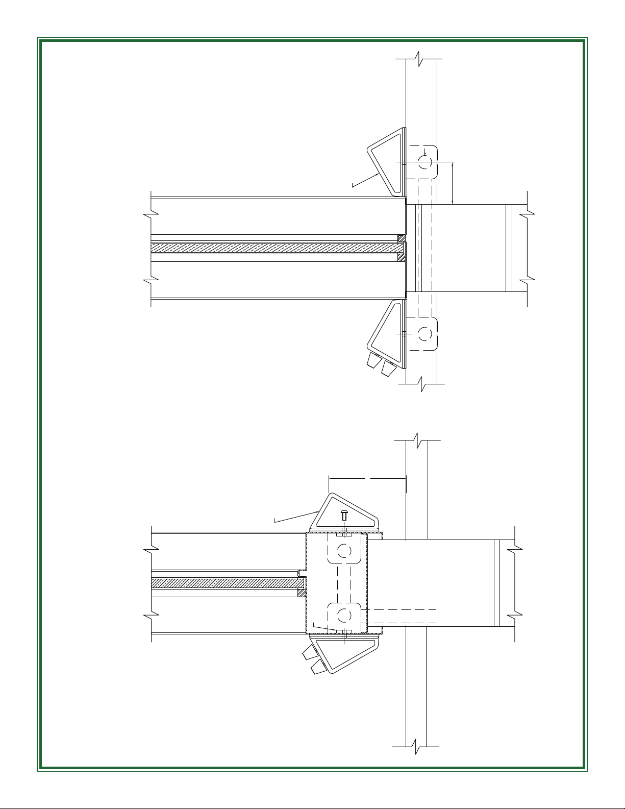
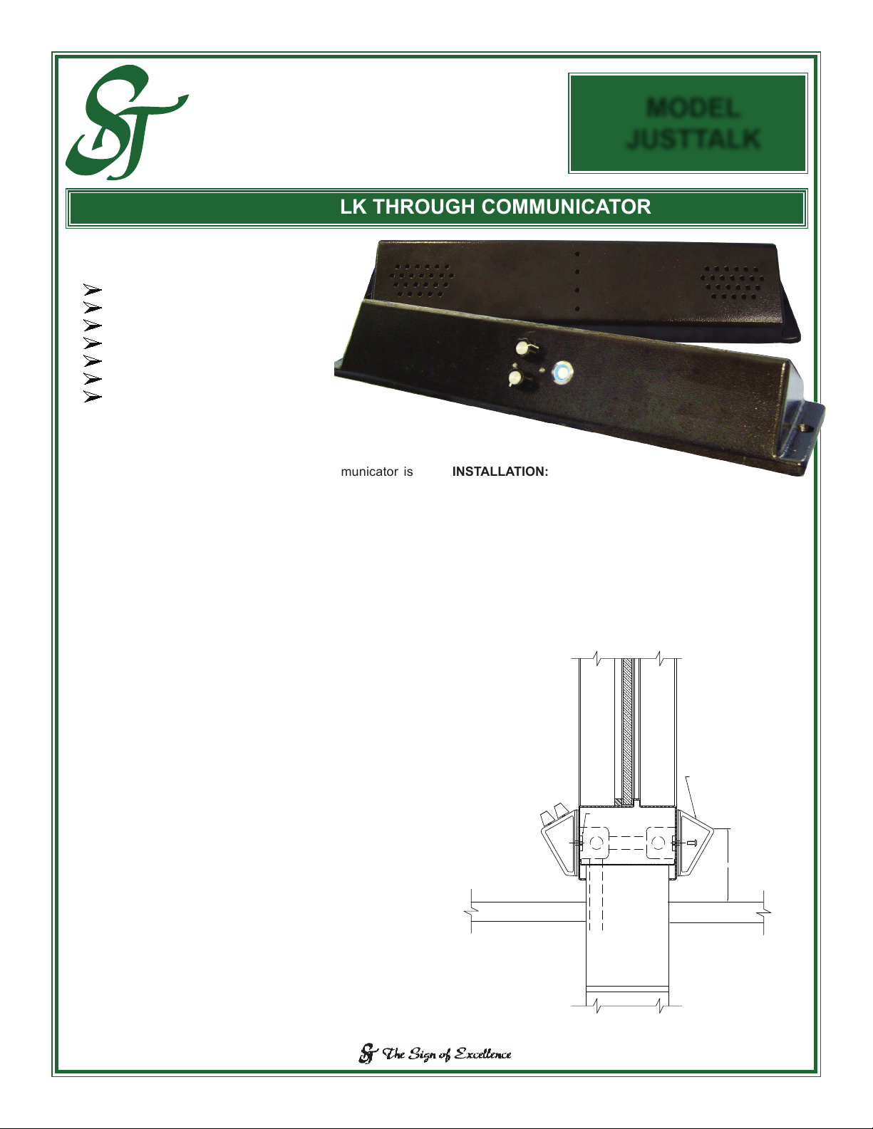
INSTALLATION:
The recommended mounting location is on a 4" high hollow
metal window frame sill, centered between sidewall parti-
tions, with the speakers and microphones side pointing down
towards the countertop reective surface.
An alternate mounting location is upon the countertop, cen-
tered between sidewall partitions, with the speakers and
microphones side facing towards the viewing window.
SECTION 2 - 7 3/11
MODEL
JUSTTALK
DUPLEX TALK THROUGH COMMUNICATOR
WRITING SURFACE
4.0000
RECOMMENDED LOCATION
1/4-20UNC THROUGH
7 GA STEEL SCREW BLOCKS
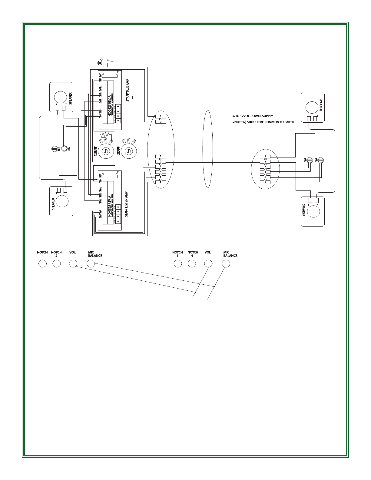
POWER - TYPICAL
JUSTTTALK-V2 SHOWN
2.75
12VDC POWER
PATH
ALTERNATE LOCATION