ST UM0767 User manual

May 2010 Doc ID 16147 Rev 1 1/30
UM0767
User manual
STEVAL-ILL024V1 and STEVAL-ILL025V1 demonstration boards
based on the STP16DP05 LED matrix driver and STM32F103VB
Introduction
This user manual describes the operation of the STM32F103VB-based LED matrix display
demonstration board. This board demonstrates the capability of the STP16DP05 LED driver
to drive the matrix LED panel. The complete system includes one master board, one slave
board and LED matrix display panels. The master and slave boards are STM32F103VB
microcontroller-based control units which are used for configuring the display settings for the
STP16DP05 display driver. This unit has a GPS module interfaced through a USART port.
The GPS data can be displayed with information on latitude and longitude and also a real-
time clock. The display can be configured for any of the nine different display modes and
nine different speeds using a PS2 keyboard. Display panels can also be configured through
the HyperTerminal using the serial interface present on the control units. The system also
consists of audio-out for playing back the .wav file pre-recorded in the microSD cardTM.
Figure 1. STEVAL-ILL025V1, LED display panel
!-V
www.st.com

Contents UM0767
2/30 Doc ID 16147 Rev 1
Contents
1 Getting started . . . . . . . . . . . . . . . . . . . . . . . . . . . . . . . . . . . . . . . . . . . . . . 4
1.1 Package contents . . . . . . . . . . . . . . . . . . . . . . . . . . . . . . . . . . . . . . . . . . . . 4
1.2 Hardware description . . . . . . . . . . . . . . . . . . . . . . . . . . . . . . . . . . . . . . . . . 4
1.3 Power supply unit . . . . . . . . . . . . . . . . . . . . . . . . . . . . . . . . . . . . . . . . . . . . 5
2 System description . . . . . . . . . . . . . . . . . . . . . . . . . . . . . . . . . . . . . . . . . . 7
2.1 Description of the STEVAL-ILL024V1 microcontroller-based control unit . 7
2.1.1 Address configuration of the control unit . . . . . . . . . . . . . . . . . . . . . . . . . 7
2.1.2 Selecting the control unit as master or slave . . . . . . . . . . . . . . . . . . . . . . 8
2.2 Description of the STEVAL-ILL025V1 LED driver-based display unit . . . . 8
3 System configuration . . . . . . . . . . . . . . . . . . . . . . . . . . . . . . . . . . . . . . . 10
3.1 One control unit and one display unit configuration . . . . . . . . . . . . . . . . . 10
3.2 Two control units and one display unit configuration . . . . . . . . . . . . . . . . 11
3.3 Multiple control and display unit configuration . . . . . . . . . . . . . . . . . . . . . 13
4 System operation modes . . . . . . . . . . . . . . . . . . . . . . . . . . . . . . . . . . . . 15
4.1 PC-UART communication mode . . . . . . . . . . . . . . . . . . . . . . . . . . . . . . . 15
4.2 GPS communication mode . . . . . . . . . . . . . . . . . . . . . . . . . . . . . . . . . . . . 18
4.3 Key board typing mode . . . . . . . . . . . . . . . . . . . . . . . . . . . . . . . . . . . . . . . 18
4.4 Demo mode . . . . . . . . . . . . . . . . . . . . . . . . . . . . . . . . . . . . . . . . . . . . . . . 19
5 Schematics and BOM list . . . . . . . . . . . . . . . . . . . . . . . . . . . . . . . . . . . . 21
6 Revision history . . . . . . . . . . . . . . . . . . . . . . . . . . . . . . . . . . . . . . . . . . . 28

UM0767 List of figures
Doc ID 16147 Rev 1 3/30
List of figures
Figure 1. STEVAL-ILL025V1, LED display panel . . . . . . . . . . . . . . . . . . . . . . . . . . . . . . . . . . . . . . . . 1
Figure 2. STEVAL-ILL024V1, LED matrix control unit . . . . . . . . . . . . . . . . . . . . . . . . . . . . . . . . . . . . . 5
Figure 3. Power supply connection on control unit . . . . . . . . . . . . . . . . . . . . . . . . . . . . . . . . . . . . . . . 6
Figure 4. Power supply connection for the LED display panel. . . . . . . . . . . . . . . . . . . . . . . . . . . . . . . 6
Figure 5. Slave unit address configuration switches . . . . . . . . . . . . . . . . . . . . . . . . . . . . . . . . . . . . . . 8
Figure 6. Connection of display panels . . . . . . . . . . . . . . . . . . . . . . . . . . . . . . . . . . . . . . . . . . . . . . . . 9
Figure 7. RS485 communication . . . . . . . . . . . . . . . . . . . . . . . . . . . . . . . . . . . . . . . . . . . . . . . . . . . . 12
Figure 8. RS485 multi-drop topology . . . . . . . . . . . . . . . . . . . . . . . . . . . . . . . . . . . . . . . . . . . . . . . . 14
Figure 9. ASCII settings of the HyperTerminal in the computer. . . . . . . . . . . . . . . . . . . . . . . . . . . . . 17
Figure 10. MicroSD card connection . . . . . . . . . . . . . . . . . . . . . . . . . . . . . . . . . . . . . . . . . . . . . . . . . . 20
Figure 11. Schematic for the control unit . . . . . . . . . . . . . . . . . . . . . . . . . . . . . . . . . . . . . . . . . . . . . . . 21
Figure 12. LED display panel schematic . . . . . . . . . . . . . . . . . . . . . . . . . . . . . . . . . . . . . . . . . . . . . . . 22

Getting started UM0767
4/30 Doc ID 16147 Rev 1
1 Getting started
1.1 Package contents
●The STM32-based LED matrix display demo package consists of the hardware and
supporting documentation.
– Hardware: one demonstration motherboard + one LED matrix display panel
– Documentation: user manual for operating the demonstration board.
1.2 Hardware description
This complete system has one control unit and a display unit. The control unit is a
microcontroller-based demonstration board and the display unit is an LED matrix board.
●The major components on the STEVAL-ILL024V1 control unit are:
– STM32F103VBT6, 32-bit microcontroller
– ST485ABDR, RS485 transceiver
– LD1086DT33TR, voltage regulator
– ST3232BDR, RS232 transceiver
– TS461CLT, rail-to-rail operational amplifier
– TDA2822D, post amplifier
– STM1001RW6XF, reset IC
– STPS1L30A, Schottky diode
– 16 x 2 alphanumeric LCD
– Mini USB connector
– Screw type connector for external power supply
●Major components on the STEVAL-ILL025V1 display unit are:
– STP16DP05MTR, display driver
– TIP105, Darlington pair
– M74HC245RM13TR, buffer
– 16 x 32 LED matrix

UM0767 Getting started
Doc ID 16147 Rev 1 5/30
Figure 2. STEVAL-ILL024V1, LED matrix control unit
1.3 Power supply unit
The power supply for the control unit is 5 V - 0.5 A DC and for each display board it is 3.5 V
-5 V / 3 A DC.
The power supply for the display unit is required to be linear supply.
Both the control unit and display unit have one screw-type connector each for power supply
connection. Figure 3 shows the power supply connection for the control unit and Figure 4
shows the power supply connection for the display unit. In each display panel there are 2
screw-type connectors for power connection. VCC+5 V0 and GND are mentioned on each
of these connectors. Power can be applied to either of these two connectors to power the
LED panel. Each panel is to be powered externallyand individually.
!-V
#ONNECTORFOR
EXTERNALSPEAKERS
!DDRESSSELECTION
SWITCHES
0#5ART$"
CONNECTOR
'03MODULE$"
CONNECTOR
7AGOCONNECTOR
FORPOWER
XHEADERFOR&2#
CABLECONNECTIONTO
DISPLAYPANEL
*4!'CONNECTORFOR
PROGRAMMING
7AGOCONNECTORFOR
23CONNECTION
03CONNECTOR
KEYBOARDCONNECTION
.UMERICKEYPAD

Getting started UM0767
6/30 Doc ID 16147 Rev 1
Figure 3. Power supply connection on control unit
Figure 4. Power supply connection for the LED display panel

UM0767 System description
Doc ID 16147 Rev 1 7/30
2 System description
This STM32-based display demo system has a microcontroller-based control unit and an
LED driver-based display unit. The control unit is used for configuring the display driver and
the display unit is used for controlling the LED display in accordance with the configuration
received from the control unit.
2.1 Description of the STEVAL-ILL024V1 microcontroller-based
control unit
The STEVAL-ILL024V1 control unit is an STM32 microcontroller-based board. This board
has interfaces for:
–PS2keyboard
– DB9 (female) connector for PC serial port (UART) connection
– DB9 (male) connector for serial (UART) connection to GPS module
– On-board numeric keypad
– Audio jack and 2-pin connector for the external speaker
– Wago connector for RS485 communication between the master and slave control
units
– 10 x 2 header (Ext.Con) for flat-ribbon cable connection to display unit
– Slot for microSD card
– Screw type connector for 5 V DC power connection
This microcontroller-based unit is used to control the display board. This unit can be
configured to operate as the master (responsible for sending the commands for display
control) or as the slave unit (responsible for receiving the commands and executing them on
the display unit). In every system, one control unit acts as a master.
2.1.1 Address configuration of the control unit
Each control unit has 8 switches (SW2). These switches are used to configure the address
for the control unit.
Address configuration for the control unit is done by moving the switches to either high or
low positions.
Eight I/O lines are used for address allocation to the control unit. Therefore, up to 255
addresses can be assigned to any control board. The board can have any number of
addresses between 0 and 255.
If the switch is slid towards the numbered side, then logic '1' is assigned to the port, if the
switch is slid towards the “on” side, then logic '0' is assigned to the board.
Whenever the board is powered-up and is connected as a slave unit then its address is
displayed on the LCD mounted on-board. Figure 5 shows the on-board switches.
Note: Address 255 is hardcoded to the master unit and no slave unit is allowed to have this
address. Therefore, one should never slide all 8 switches to the numbered side (opposite
the side where “on” is written).

System description UM0767
8/30 Doc ID 16147 Rev 1
Figure 5. Slave unit address configuration switches
2.1.2 Selecting the control unit as master or slave
Any control unit can act as the master or slave. The on-board keypad is used to configure
the control unit as master or as slave.
The steps for configuring the control unit are listed below:
– Connect a 5 V power supply to the control unit, as explained in Section 1.3
– The LCD shows “Press “#” to enter Configuration Mod”, for 4 seconds
– Press “#” on the keypad present on the board. The LCD shows “Master Sel: Entr
*1” and “Slave Sel: Entr *2”
– To configure the board as the master, press “*1” or to configure the board as the
slave press “*2” on the keypad
– If “*1” is pressed, then the LCD shows “Master Board” for 2 seconds and then
starts the master routine on the board
– If “*2” is pressed, then the LCD shows “Slave Board” for 2 seconds and then starts
the slave routine on the board.
– On the next power-up of the board the message “Press “#” to enter Configuration
Mod” is again shown on the LCD for 4 seconds, but if “#” is not pressed within 4
seconds, the board enters into the last configured mode.
2.2 Description of the STEVAL-ILL025V1 LED driver-based
display unit
The STEVAL-ILL025V1 display unit is an STP16DP05 LED display driver-based panel.
Each display panel has four STP16DP05 LED display drivers, two buffers, eight Darlington
pairs and a matrix of 16 x 32 LEDs. Each panel can be connected in series to create a larger
display. Series connection between the display panels is done through a 10 x 2 header. A
20-pin flat-ribbon cable is used to connect the two display panels. Input to the display panel
comes from the control unit through the 20-pin flat-ribbon cable. Therefore, the first display

UM0767 System description
Doc ID 16147 Rev 1 9/30
panel is connected to the control unit to receive the data and also to the next display panel
to cascade the data further. A total of 8 such panels can be cascaded in series.
Figure 6 shows the connection of the display panel. The first panel is connected at both
sides, one to the control unit, using a 20-pin cable between the Ext Con header on the
control unit and the input header at the display panel, and the other to the second display
panel using the output header at the first panel and the input header at the second panel.
Figure 6. Connection of display panels

System configuration UM0767
10/30 Doc ID 16147 Rev 1
3 System configuration
The whole system can be connected in one of the following configurations:
●One control unit and one display unit without a slave unit
●Two control units (one acting as a master and the other as a slave) and one display unit
●Multiple control units (one acting as a master and the others as slaves) and multiple
display units (each display unit connected to each slave. One display unit can have up
to 8 cascaded panels that may be controlled by a single slave unit.)
3.1 One control unit and one display unit configuration
In this configuration there is a single control unit and a single display unit. The control unit
acts as the master.
The steps to operate the system in this configuration are listed below:
●Step 1: connect the PS2 keyboard to the control unit.
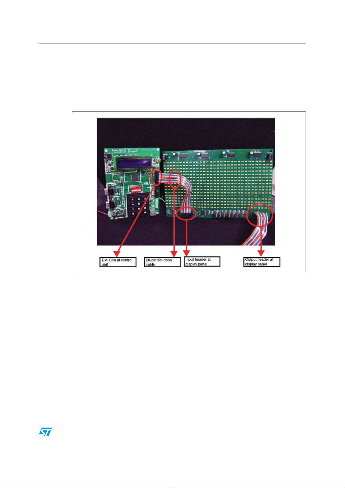
●Step 2: connect the control unit with the display panel using a 20-pin flat-ribbon cable.
Insert the cable into the 10 x 2 header (Ext.Con) present on the master on one side and
in the J1 header (input) on the display panel on the other side.
If needed, the display panels can be cascaded in series to create a longer display. To
cascade the display panels connect a 20-pin flat-ribbon cable from the J3 jumper (output) of
the first panel to the J1 jumper (input) of the second panel. Figure 6 shows the connections
for cascading the display panels. Similarly, connect the FRC cable from the J3 jumper
(output) of the second panel to the J1 jumper (input) of the third panel and so on to create a
longer display. Up to 8 such display panels can be cascaded in series.
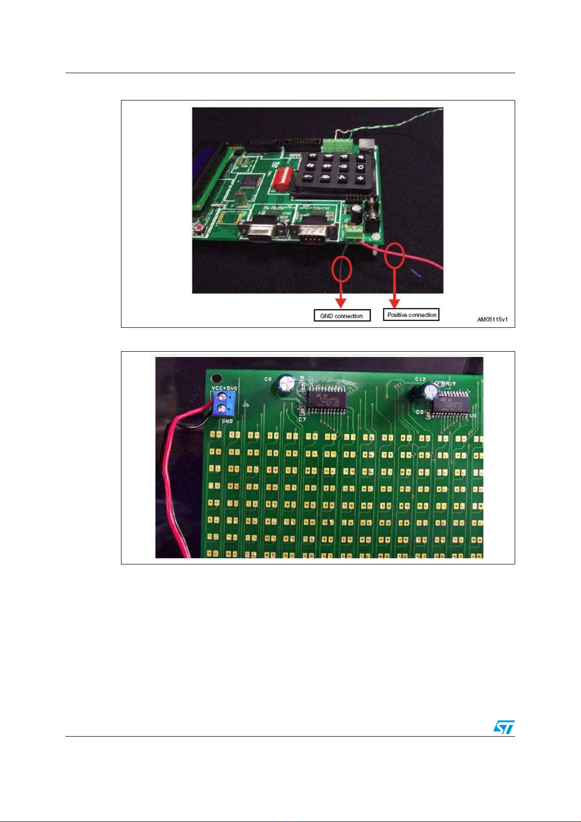
●Step 3: connect the power to the master control unit and to the display panel, as
explained in Section 1.3.
●Step 4: the LCD on the master control unit shows “Press “#” to enter Configuration
Mod”, for 4 seconds.
●Step 5: press “#” on the keypad present on the board. If 4 seconds elapse and the
board is not configured, then it enters into the last configured mode. To configure it
again, press the reset button.
●Step 6: if “#” is pressed then the LCD shows “Master Sel: Entr *1” and “Slave Sel: Entr
*2”.
●Step 7: press “*1” on the keypad. The LCD shows “Master Board”.
●Step 8: after 2 Seconds the LCD starts the demo showing “Led Matrix Demo”.
●Step 9: the display starts showing 4 options:
– Press F1 For PC - UART Comm
– Press F2 For GPS Data Display
– Press F3 For Typing Data
– Press F6 For Demo Mode
●Step 10: press F1, F2, F3 or F6 on the keyboard to select one of the above mentioned
modes.
●Step 11: based on which of the keys listed above is pressed, the system enters into the
chosen mode. Operation in each mode is explained in Section 4.

UM0767 System configuration
Doc ID 16147 Rev 1 11/30
●Step 12: press Esc on the keyboard to exit the selected mode.
●Step 13: once out of the selected mode, the system resumes from step 9.
3.2 Two control units and one display unit configuration
In this configuration there are two control units and a single display unit. One control unit
should be the master and the second should be the slave. By default, the system comes
with one master and one display panel.
The steps to operate the system in this configuration are listed below:
●Step 1: configure one control unit as the master and the second control unit as the
slave, as explained in Section 2.1.2.
●Step 2: configure the address of the slave board using the on-board DIP switches, as
explained in Section 2.1.1.
●Step 3: connect the PS2 keyboard to the master control unit.
●Step 4: connect the display panel to the slave control unit using a 20-pin flat-ribbon
cable. Insert the cable into the 10 x 2 header (Ext.Con) present on the slave at one side
and into the J1 header (input) on the display panel at the other side.
If needed, the display panels can be cascaded in series to create a longer display. To
cascade the display panels connect a 20-pin flat-ribbon cable from the J3 jumper (output) of
the first panel to the J1 jumper (input) of the second panel. Figure 6 shows the connections
for cascading the display panels. Similarly, connect the FRC cable from the J3 jumper
(output) of the second panel to the J1 jumper (input) of the third panel and so on to create a
longer display. Up to 8 such display panels can be cascaded in series.
●Step 5: connect the master and the slave control unit using a twisted pair cable. Ensure
that RS485+ at master is connected to RS485+ at slave and RS485- at master is
connected to RS485- at slave. Connections are made at the J18 screw type connector.
Figure 7 shows the RS485 connection topology.
●Step 6: power-up the master control unit, the slave control unit and the display panel
using DC power supplies.
●Step 7: the LCD on the master and slave control unit shows “Press “#” to enter
ConfigurationMod”. This is displayed for 4 seconds. If the master and slave boards are

System configuration UM0767
12/30 Doc ID 16147 Rev 1
already configured in Step 1, don't press “#”, the board then resumes functioning after
4 seconds.
●Step 8: the master control unit starts the demo showing “LED Matrix Demo” and the
slave control unit starts showing its own address. (The address is configured using on-
board switches).
●Step 9: the display at master shows 4 options:
– Press F1 for PC - UART Comm
– Press F2 for GPS data display
– Press F3 for typing data
– Press F6 for demo mode
●Step 10: press F1, F2, F3, or F6 on the keyboard, attached to the master board, to
select one of the above mentioned modes.
●Step 11: based on which of the keys listed above is pressed, the system enters into the
chosen mode. Operation in each mode is explained in Section 4.
●Step 12: the master control unit sends commands to the slave control unit. The slave
control unit processes these commands and configures the display panel to display the
entered data.
●Step 13: press Esc on the keyboard attached to the master board to exit the present
mode. After this, the system resumes from step 9. If the new address entered for the
slave selection matches with the slave address then the slave display is interrupted, or
else the display continues with the old data.
Figure 7. RS485 communication

UM0767 System configuration
Doc ID 16147 Rev 1 13/30
3.3 Multiple control and display unit configuration
In this configuration there are multiple control units and multiple display panels. One control
unit should be the master and the others slaves. By default, the system comes with one
master and one display panel.
The steps to operate the system in this configuration are listed below:
●Step 1: configure one control unit as the master and the other control units as slaves,
as explained in Section 2.1.2.
●Step 2: configure the address of the slave boards using the on-board DIP switches, as
explained in Section 2.1.1.
●Step 3: connect the PS2 keyboard to the master control unit.
●Step 4: connect the display panels to each slave control unit using a 20-pin flat-ribbon
cable. Insert the cable into the 10 x 2 header (Ext.Con) present on the slave at one side
and in the J1 header (input) on the display panel at the other side.
If needed, the display panels can be cascaded in series to create a longer display. To
cascade the display panels connect a 20-pin flat-ribbon cable from the J3 jumper (output) of
the first panel to the J1 jumper (input) of the second panel. Figure 6 shows the connections
for cascading the display panels. Similarly, connect the FRC cable from the J3 jumper
(output) of the second panel to the J1 jumper (input) of the third panel and so on to create a
longer display. Up to 8 such display panels can be cascaded in series.
●Step 5: connect the master and the slave control units using a twisted pair cable.
Ensure that RS485+ at master is connected to RS485+ at slave and RS485- at master
is connected to RS485- at slave. Connections are made at the J18 screw type
connector. Figure 8 shows the RS485 connection topology.
●Step 6: power-up the master control unit, the slave control units and the display panels
using DC power supplies. Please ensure that when cascading the display panels,
power should be individually supplied at the J5 screw type connector on each display
panel.
●Step 7: the LCD on the master and slave control unit shows “Press “#” to enter
ConfigurationMod”. This is displayed for 4 seconds. If the master and slave boards are
already configured in Step 1, don't press “#”, the board then resumes functioning after
4 seconds.
●Step 8: the master control unit starts the demo showing “LED Matrix Demo” and the
slave control unit starts showing its own address. (The address is configured using on-
board switches).
●Step 9: the display at master shows 4 options:
– Press F1 For PC - UART Comm
– Press F2 For GPS data display
– Press F3 for typing data
– Press F6 for demo mode
●Step 10: press F1, F2, F3, or F6 on the keyboard to select one of the above mentioned
modes.
●Step 11: based on which of the keys listed above is pressed, the system enters into the
chosen mode. Operation in each mode is explained in Section 4.
●Step 12: the master board LCD asks for the address of the slave control unit in order to
configure the display unit.

System configuration UM0767
14/30 Doc ID 16147 Rev 1
If the address entered at the master unit matches with the slave unit then the selected slave
unit can be configured for display, or else “Address Mismatch” is displayed on the LCD and a
new address entry is requested.
●Step 13: when the address is matched, the master control unit sends commands to the
selected slave control unit. The slave control unit processes these commands and
configures the display panel to display the entered data. The other slave units continue
to display the old data.
●Step 14: press Esc to exit the present mode; after this, the system resumes from Step
9. If the new address entered (for slave selection) matches with the slave address then
the slave display is interrupted, or else the display continues with the old data.
Figure 8. RS485 multi-drop topology
Note: R is the termination resistance used for impedance matching.

UM0767 System operation modes
Doc ID 16147 Rev 1 15/30
4 System operation modes
The LED display demo board has 4 different modes of operation. These are:
●PC-UART communication mode
●GPS module communication mode
●Keyboard typing mode
●Demo Mode
As soon as the master control unit is powered-up, the LCD on the master board shows
“Master Board” for the first 2 seconds, then a menu is started which requests that F1, F2,
F3, or F6 is pressed to select one of the above mentioned modes.
4.1 PC-UART communication mode
The master control unit communicates with the computer using UART communication
protocol. The female DB9 connector on the control unit is used to connect to a computer
using a serial connection cable.
The steps for communicating using the HyperTerminal of the computer are listed below:

System operation modes UM0767
16/30 Doc ID 16147 Rev 1
Steps:
●Connect a serial cable between the serial port of the computer and the female DB9
connector of the master control unit (VB1).
●Connect the PS2 keyboard to the master control unit.
●Configure the HyperTerminal on the computer using the following settings:
– Bits per second: 115200
– DataBits: 8
– Parity: none
– Stop bits: 1
– Flow control: none
●Configure the ASCII settings as shown in Figure 9.
●Power-up the master control unit, the LED panel and also the slave control unit (if
connected).
●The LCD on the master displays the menu program which shows “Press F1 for PC-
UARTComm”.
●Press the F1 key on the keyboard attached to the PS2 connector of the master control
unit.
●The HyperTerminal shows the message
– “USART HyperTerminal communication demo maximum allowed string length is
200 Words”
– “Enter display board address, Enter 1-255”
●Enter the slave control unit address (as seen on the LCD of the slave control unit) or
the address of the master (255), and then press the “Enter” key on the PC keyboard.
Addresses allowed are between 1 and 255.
●If the entered address is not present there is an error message on the HyperTerminal,
“Address Mismatch; enter display board address”. Check the address of the slave
board and then re-enter it on the HyperTerminal.
●When the address is matched, the message on the HyperTerminal is “Enter no. of LED
boards”. Enter the number of LED display panels connected in cascade to the selected
control unit (one LED display panel constitutes 16x32 LED's). A maximum of 8 panels
can be connected to any one control unit.
●The next message is “enter mode; Entr between 1-9”. This is for entering one of the 9
display modes. These are the following:
– Mode 1 => curtain up
– Mode 2 => curtain down
– Mode 3 = > left to right scroll
– Mode 4 => right to left scroll
– Mode 5 => typing data mode
– Mode 6 => stable display
– Mode 7 => flashing mode
– Mode 8 => curtain right
– Mode 9 => curtain left

UM0767 System operation modes
Doc ID 16147 Rev 1 17/30
If the mode entered is other than 1-9 then the default mode is selected and this message is
seen on the terminal: “Default Mode: Right To Left”
●As soon as the mode is entered, the selected mode is seen on the HyperTerminal and
the next message is “Enter Speed; Entr between 1-9”. This speed is to see the display
on the LED matrix. Speed 1 is fastest and 9 is slowest. If the speed entered is other
than 1-9 then the default speed of 2 is selected.
●The next message is “Enter String”.
●Enter the string (the maximum allowed string length is 200 letters). When the required
string is entered, select the Enter key on the keyboard.
●Data is sent to the LED matrix display and can be seen there.
●The next message on the HyperTerminal is “Enter Y to re-enter display mode settings
or any other key to exit PC-UART mode:” Therefore if Y is entered, the HyperTerminal
again shows a message asking for the slave address. If any other key is entered then
the system exits PC-UART mode and the normal menu is seen on the master control
unit LCD.
Figure 9. ASCII settings of the HyperTerminal in the computer

System operation modes UM0767
18/30 Doc ID 16147 Rev 1
4.2 GPS communication mode
Global positioning system (GPS) mode is used for interacting with an externally connected
GPS module and display time, latitude, longitude and satellite fixture status.
The steps for communicating with a GPS module are listed below:
Steps:
●Connect a serial cable between the GPS module and the DB9 male connector (VB2) of
the master control unit. The GPS system should follow the handshaking protocol for
serial communication.
●Connect the PS2 keyboard to the master control unit.
●Power-up the master control unit, the LED panel, and the slave control unit (if
connected).
●The master LCD shows the menu program which displays “Press F2 for GPS data
display”.
●Press the F2 key on the keyboard attached to the PS2 connector of the master control
unit.
●The master LCD shows the GPS mode selected and “Enter Display Board Address”.
Enter the slave board address where data is to be displayed on the LED matrix panel.
Addresses allowed are between 1 and 255. 255 is fixed for the master unit. If the wrong
data is entered the LCD shows “Address Mismatch” and again asks for the address.
●When the address is matched, the LCD asks for the number of display panels
connected in cascade at the selected slave device to be entered.
●As soon as the number of display panels is entered, the LED matrix starts showing
time, latitude, longitude and satellite fixture status.
●Press Esc on the keyboard to exit GPS mode and return to the main menu.
Note: The GPS module interface is configured for 115200 baud rate.
4.3 Key board typing mode
This mode is for user interaction using the keyboard attached at the PS2 connector on the
motherboard.
The steps for operating in typing mode are listed below:
Steps:
●Connect the keyboard to the PS2 connector on the master control unit.
●Power-up the master control unit, the LED panel, and the slave control unit (if present).
●The master LCD shows the menu program which displays “Press F3 for typing data”.
●Press the F3 key on the keyboard attached to the PS2 connector of the master control
unit.
●The master LCD shows “Enter Display Board Address”. Enter the slave board address
where data is to be displayed on the LED matrix panel. The addresses allowed are
between 1 and 255. 255 is fixed for the master unit. If the wrong data is entered then
the LCD shows “Address Mismatch”, and again asks for the address.
●When the address is matched, the LCD shows “Enter No. Of LED Boards”. Enter the
number of LED panels connected in cascade to the selected control unit (one LED

UM0767 System operation modes
Doc ID 16147 Rev 1 19/30
display panel constitutes 16x32 LED's). A maximum of 8 panels can be connected to
any one control unit.
●The next message is “Enter Mode; Entr between 1-9”. This is for entering one of 9
display modes. The modes are explained in step 12 of Section 4.1.
●As soon as the mode is entered, the selected mode is seen on the LCD which then
shows “Enter Speed; Entr between 1-9”. This speed is to see the display on the LED
matrix. Speed 1 is fastest and 9 is slowest. If the speed entered is other than 1-9, the
default speed of 2 is selected.
●The next message is “Enter String; Pres Esc to exit”.
●Enter the data which is to be seen on the LED matrix display. If the user does not want
to enter data and wants to exit this mode, the Esc key should be pressed.
●As soon as the data is entered, it is seen on the LED matrix and the LCD shows “Pres
Esc to exit; Enter to Proceed”. Therefore to continue with the typing mode select the
“Enter” key on the keyboard, the system again asks for the slave board address, or else
select the Esc key to exit this mode and return to the main menu.
Note: To check if caps lock is on or off, see the characters on the LCD. If caps lock is on then the
letters are seen in capital case on the LCD, alternatively they are in small case.
4.4 Demo mode
Demo mode is executed with the master control unit and the display panel connected to
“Master unit”. This mode is supported with audio output.
The steps for demo mode are listed below:
●Steps:
– Save an audio file in .wav format in the microSD card. Save the audio file with the
name “STN2”. Configuration of the audio file should be: 8 Bit, 8 kHz mono. This is
the audio heard from the board.
– Insert the microSD card in the memory card slot connected at the back of the
master, as shown in Figure 10.
– Connect a display panel to the master control unit using a 20-pin flat-ribbon cable.
– Connect the PS2 keyboard to the master unit.
– Connect an external speaker to the two-pin audio connector (near the audio jack)
or to the audio jack. The audio jack has a mono output only.
– Power-up the master control unit and the display panel.
– The LCD menu is started. It shows “Press F6 for Demo Mode”. Press the F6 key to
enter demo mode.
– As soon as F6 is pressed, the LCD shows a message for entry of the display panel
number “Enter No. Of LED Boards”. Enter the number of display panels connected
to the master unit.
– After the number of led panels is entered, the audio file saved as STN2 in the
microSD card is played on the speaker and the LED panel shows the message:
“Wish You A Happy Journey”.
– Press the Esc key to exit this mode and return to the menu.

System operation modes UM0767
20/30 Doc ID 16147 Rev 1
Note: For demo mode, the microSD card should be inserted into the card slot, or no data display
occurs. The Esc key is used to exit this mode at any time.
At any point of the system, press Esc twice on the keyboard attached to the master unit to
return to the main menu.
Until one of the system modes is entered, by pressing any key other than F1, F2, F3, or F6,
the message “Key Not Allowed” is shown.
In PC USART mode the keyboard attached to the mother unit is not active for data entry.
Only the Esc key is functional in this mode.
Figure 10. MicroSD card connection
Table of contents
Other ST Monitor manuals