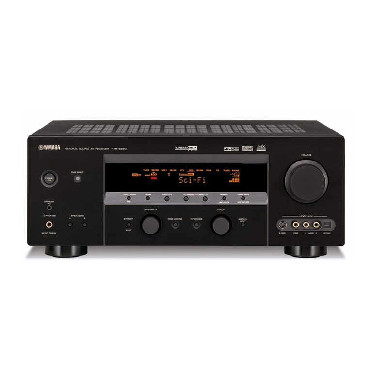
Standard Communications mt930b User manual

SERVICE
MANUAL
SERVICE
MANUAL
SATELLITE
9130B
S
tandard
Communications
CommunicationsCommunications
Communications
™
MULTIFUNCTIONDISPLAY
SELECT
OFF
ON
AFCAGC
OFFON
CONTROL
MGC
FINE
TUNEAUDIO#1AUDIO#2AUDIO#3
VIDEOTEST
70MHzIF
CONTENTS
SAFETYADVISORY
GENERAL INFORMATION
MT930B SPECIFICATIONS
CONTROLS AND CONNECTIONS
INSTALLATION AND SETUP
PRINCIPLES OF OPERATION
MAINTENANCE
MAINTENANCE OPTIONS
TROUBLESHOOTING PROCEDURES
BLOCK DIAGRAMS AND SCHEMATICS

MT930B
SERVICE MANUAL
This manual is intended for experienced application developers. The manual
contains the information needed to understand the MT930B protocol. This
protocol allows a control program running on a personal computer to manage
multiple MT930B receivers. Changes that occur after the date of printing will be
incorporated in supplemental bulletins or later editions of this manual.
This document is the property of Standard Communications Corp., and embodies
proprietary subject matter of Standard Communications Corp. All design,
manufacture, reproduction, use, and sale rights regarding the same are expressly
reserved. This document may not be reproduced without written consent from
Standard Communications Corp. All copyright, patent, and trade secrets are
expressly reserved by Standard Communications Corp.
Standard
Communications
™
Printed 11/99
Please address all correspondence to:
MA00011-01
Printed in U.S.A.
Standard Communications Corp.
United States Corporate Headquarters
6260 Sequence Drive, San Diego, CA 92121
Toll Free: 800-745-2445
Phone: 858-546-5300
Fax: 858-546-5301
www.standardcom.com

MT930B Service Manual Page i

Page ii Service Manual MT930B
SAFETY ADVISORY
1. Read These Instructions First=−All safety and operating instructions
should be read before installing or operating this equipment. Safety and
operating instructions should be retained for future reference.
2. Cleaning=−Unplug the equipment from the AC power outlet before
cleaning. Do not use liquid or aerosol cleaners.
3. Ventilation=−Do not block or cover slots and openings in this equipment.
These are provided for ventilation and protection from
overheating.
4. Power Sources=−Operate this equipment only from the type of power
source indicated on the rear panel.
5. Grounding or Polarization=−This equipment is equipped with a polarized
AC line plug. This plug will fit into the power
outlet only one way. If you are unable to in-
sert the plug into the outlet, try reversing
the plug. If the plug still does not fit, contact
your electrician to replace your obsolete
outlet. Do not defeat the safety purpose of
a polarized plug.
6. Servicing −Refer all servicing
to qualified SCC personnel.
Opening or removing covers
may expose dangerous volt-
ages. When replacement
parts are required, make
sure the service technician
uses only replacement parts
recommended by SCC.
Unauthorized substitutions
may result in fire, electric
shock, or improper operation
of the unit.
7. Lightning=−For added
protection during a lightning
storm or when the equipment
is left unattended or unused
for long periods, unplug it
from the power outlet and
disconnect the cables be-
tween the equipment and the
antenna subsystem. These
precautions will prevent
damage to the equipment
that could be caused by
lightning strikes or power line
surges.
NOTE: This reminder is provided to CATV
systeminstallers to call your attention to
NEC Articles 810-21, 820-22, and
820-40 that provide guidelines for
proper grounding. In particular, these
articles specify that the cable ground
shall be connected to the building
grounding system, as close to the point
of cable entry as practical (see Figure
1).
9001
Figure 1. Typical Antenna Grounding
CAUTION: For continued protection against
risk of fire, replace the fuse (if necessary)
with one of only the same type and rating.

Contents
MT930B Owner’s Manual Page iii
CONTENTS
SAFETY CONSIDERATIONS................................................................................i
IMPORTANT SAFEGUARDS...............................................................................ii
READ ME !......................................................................................iv (next page)
INTRODUCTION............................................................................................... 1-1
MT930B SERIES SPECIFICATIONS ............................................................... 2-1
CONTROLS AND CONNECTIONS.................................................................. 3-1
Front Panel............................................................................................. 3-1
Rear Panel ............................................................................................. 3-2
Internal Controls/Settings....................................................................... 3-3
INSTALLATION................................................................................................ 4-1
Rack mounting ....................................................................................... 4-1
Connections ........................................................................................... 4-1
OPERATION..................................................................................................... 5-1
User Interface......................................................................................... 5-1
Front Panel Operations .......................................................................... 5-1
Menu Architecture on the LCD Display................................................... 5-2
Rules of Navigation ................................................................................ 5-3
Operating Modes.................................................................................... 5-5
Menu Contents....................................................................................... 5-6
Active Channel Menu....................................................................... 5-6
Database Set Up and Entry Menu................................................. 5-10
Alarm Set Up Menus...................................................................... 5-17
Timer Menus.................................................................................. 5-18
Receiver Configuration Menus....................................................... 5-21
Receiver Version Menu ................................................................. 5-24
OPTIONS.......................................................................................................... 6-1
REMOTE CONTROL OPERATION.................................................................. 7-1
Overview ................................................................................................ 7-1
RS-232C Transmission Conditions ........................................................ 7-2
Command Formats................................................................................. 7-3
BLOCK DIAGRAM ........................................................................................... 8-1
LIMITED WARRANTY
GOLD STANDARD PROGRAM

Contents
Page iv Owner’s Manual MT930
READ ME !
Most users want to do a quick check before reading all the details on the
receiver’s capabilities, so the following should get you video and audio. Please,
in the near future, read the remainder of the instructions to find out about the
great features hidden in the menus.
1. Rack mount the unit or set on bench top with air clearance.
2. Hook up an L-band signal to F connector(s) at Port 1,2,3 or 4. We
recommend C-band Vertical be connected to #1, C-Band Horizontal to #2,
Ku-band Vertical be connected to #3, Ku-Band Horizontal to #4 to maximize
the preprogrammed database which assumes these connections. Hook up
outputs as needed.
3. CHECK THAT RECEIVER IS SET TO 115 or 220 VAC as required in your
facility. Connect power cord to receiver, then to wall. Display messages or a
Port LED lighting shows you are powered up.
4. After front panel display completes startup messages, rotate MENU knob to
show #1 ACTIVE CHANNEL in top line of the display. Press EDIT and rotate
SELECT knob to obtain the satellite format you desire (e.g. ‘C-BAND’). Press
RIGHT button, then rotate SELECT knob to chose the transponder you
desire. Press SAVE to capture the changes. You should have video and
audio. If you are using a satellite that is not in the database, select one
similar (i.e., Ku band type) and edit downlink frequency, as in 6, below.
5. If you are not receiving video and audio, consider reading the entire manual
now. However, you can rotate the MENU knob and return to ACTIVE
CHANNEL again. If satellite and transponder are not those desired, repeat
above entry process. If satellite and transponder are correct, go to 6.
6. If theLED in EDIT button is on, press EDIT to turn it off. Rotate SELECT
Knob. Confirm that the parameters in each menu are correct for your input
port selection, polarity, LO, downlink frequency, etc. There are twelve sub-
menu pages to check!! In a sub-menu page, press EDIT, and move cursor
with LEFT or RIGHT BUTTON, then rotate SELECT knob. The receiver will
make the changes as you input them, real time. To back out, press EDIT
again. Press SAVE once to keep the change. To keep from messing up the
factory fresh database, press SAVE only once and press EDIT key when the
screen asks if you wish to save the change to the database.
7. Check that the LNB is powered from your facility; the receiver comes with the
LNB power blocked; rotate the Menu knob to show Menu #5-1, RECEIVER
CONFIG. LNBV will be OFF. To change, press EDIT, RIGHT button, rotate
the SELECT knob, then SAVE. This switch is global and supercedes all other
receiver settings including the LNB setting recorded in ACTIVE CHANNEL
and DATABASE SETUP.
If still no video and audio, double check the above, then read the rest of the
manual or give the folks at Standard a call.

MT930B Service Manual Page 1-1
CHAPTER 1
GENERAL INFORMATION
SCOPE
This manual is offered to Standard Communications Corp. (SCC) service dealers
to provide detailed service information for the indicated equipment. This
information includes service diagrams, parts lists and printed circuit board
layouts.
DESCRIPTION
The MT930B Satellite Receiver is an international, multi-standard, broadcast
quality 950 to 2150 MHz PLL-synthesised satellite receiver.
These units feature digitally locked, continuous-tuning AFC and
microprocessor controls. The C-band and Ku-band 950 to 2150 MHz radio
frequency (RF) inputs are dual-converted to a commercial, industrial-standard 70
MHz intermediate frequency (IF).
The MT930 Satellite Receiver design uses a new 70 MHz IF conversion circuit
that enables direct satellite processing of signal at the up/downlink site. This
circuit also provides more consistent video to the demodulator because it does
not require that the signal be processed to the baseband.
The front panel design incorporates a three-function meter that displays signal
strength, fine-tune, and carrier-to-noise (C/N).
The real-time C/N meter and alarm features consistently monitor the receiver
signals with maximum power ability. The tune meter enables precise fine-tuning
of the receive signal, and the signal meter is calibrated like a spectrum analyzer,
in dBm units.
Multiple video low-pass filters and de-emphasis networks enable the MT930B
Satellite Receiver for NTSC, PAL, SECAM, and MAC operation, along with all
known video scrambling formats. The multi-tap power supply with two voltage
settings decreases heat and power consumption, and is designed for 24-hour-a-
day operation.
FEATURES
What follows is a long list of tailored features.
•Operation, performance, and features are specifically designed for the
professional broadcaster
•PLL control of RF center frequency and audio sub-carriers

General Information
Page 1-2 Service Manual MT930B
•Front panel indication of satellite format, channel number,
upper/center/lower transponder channel, antenna polarity, audio subcarrier
frequencies, IF bandwidth, signal strength, and C/N ratio
•Remote and local control capability for all operating functions
•Four separate RF inputs
•70 MHz IF bandwidth selection capability of 16, 18, 22, 25, 27, or 36 MHz
•SAW technology for bandwidth filters
•Up to three internal audio subcarrier demodulators for #1, #2, and #3 audio
•Front panel 70 MHz IF test connector
•Connectors available for external insertion of notch filters in the 70 MHz IF
signal path
•Built-in current-limited 13 / 18 Vdc with ON / OFF for powering low-noise
block downconverters (LNBC)s and low-noise amplifiers (LNA)s
•Front panel analog meter that displays signal strength in dBm, C/N ratio,
and RF fine-tuning
•Output for remote display of signal strength
•Standard Communications' Gold Standard Support Program, 7-year
Guarantee, and Lifetime Loaner Program
•Internal nonvolatile memory for automatic selection of the following:
Transponder center frequencies
Six different 70 MHz IF bandpass filters
Antenna polarity for each channel
Audio subcarrier center frequency
Audio subcarrier bandwidth
Audio subcarrier de-emphasis values
Video polarity
Documented RS250B (satellite) broadcast proof-of-performance and
certification
Computer interface makes tracking possible and setting of multiple
receivers either on-site or remotely, using a personal computer
•Rebroadcast-quality, certified performance on NTSC, PAL, SECAM, and
MAC signals
•Precision microprocessor-controlled, dual-conversion, PLL RF tuning
•DigitalAFC tracking circuit with continuous fine-tuning ability
•70 MHz IF with spectrum inversion circuit for uplink turnarounds

General Information
MT930B Service Manual Page 1-3
•Attractive and easy to install in a standard 19-inch rack
•Low-profile chassis design, for reduced rack space consumption
•Multi-tap power supply, with two voltage settings
•High-quality terminal strips are easily wired for whichever configuration
chosen

General Information
Page 1-4 Service Manual MT930B
THIS PAGE INTENTIONALLY LEFT BLANK

M
MT
T9
93
30
0B
BS
Se
er
rv
vi
ic
ce
e
M
Ma
an
nu
ua
al
lP
Pa
ag
ge
e
2
2-
-1
1
CHAPTER 2
MT930B SPECIFICATIONS
GENERAL
Primary Power 115 / 230 (+ 6% - 10%)VAC
Line Frequency 50-60-Hz
Power Consumption ≤72 W
Operating Temperature Range 14 to 104°F (-10 to + 40°C)
Operating Altitude Range 0 to 20,000 feet (0 to 6,100 meters)
Operating Humidity Range (Non-condensing) 0 to 95%
Dimensions (H x W x D) 1.73 x 18.97 x 18.93 inches
(44 x 482 x 481 millimeters)
RF CHARACTERISTICS
RF Input Tuning Range* 950 to 2150 MHz
Tuning Step Size* 1.0 MHz
Fine Tuning Range* ± 2.0 MHz
AFC Range ± 2.0 MHz
Input Level (per Channel, Loaded with 24
Channels) - 20 to – 65 dBm
Input Impedance 75 ohms
Input Return Loss ≥9 dB
Input Isolation
Between Input 1 to 2, 3, and 4
Between Input 2 to 1, 3, and 4
Between Input 3 to 1, 2, and 4
Between Input 4 to 1, 2, and 3
≥40 dB
Gain Variation ≤8 dB
Image Rejection (1st IF) ≥30 dBc
IM3 (-25 dBm Input) ≥50 dBc
Noise Figure ≤15 dB
Local Oscillator Leakage at RF Inputs 1, 2, 3, and 4
0.9 to 2.2 GHz and 3.7 to 4.2 GHz ≤- 55 dBm
All other Frequencies ≤- 45 dBm
AGC Output (into 10 kΩLoad) 0 – 4.8 V dc
LNB Power Voltage High 550 mA ≥18.0 ≤20.0 V
Low 300 mA ≥12.7 ≤14.0 V
LNB Power Maximum Current ≥500 mA
* C-Band standard 24-channel format with 20 MHz channel step. (Continued)

Specifications
P
Pa
ag
ge
e
2
2-
-2
2S
Se
er
rv
vi
ic
ce
e
M
Ma
an
nu
ua
al
lM
MT
T9
93
30
0B
B
IF CHARACTERISTCS
1st IF Frequency 479.5 MHz
1st IF Bandwidth at –3 dB ≥40 MHz
2nd IF Frequency 70 MHz (AFC adjust in center detent)
Image Rejection (2nd IF) ≥30 dB
2nd if Bandwidth (16 MHz BPF) At – 3 16.0 ± 1.0 MHz
At – 25 ≤26.5 MHz
2nd if Bandwidth (18 MHz BPF) At – 3 18.0 ± 1.0 MHz
At – 25 ≤26.5 MHz
2nd if Bandwidth (22 MHz BPF) At – 3 22.0 ± 1.0 MHz
At – 25 ≤34.0 MHz
2nd if Bandwidth (25 MHz BPF) At – 3 25.0 ± 1.0 MHz
At – 25 ≤37.0 MHz
2nd if Bandwidth (27 MHz BPF) At – 3 27.0 ± 1.0 MHz
At – 25 ≤50.5 MHz
2nd if Bandwidth (36 MHz BPF) At – 3 36.0 ± 1.0 MHz
At – 25 ≤60.5 MHz
Spurious (by 2nd IF) ≤- 30 dBc
AGC Range for Minimum Output Level
(Max. Gain, I dB Change from Reference) ≤- 65 dBm
FM Dynamic Threshold C/N (First Sparkles) ≤13.5 dB
FM Static Threshold C/N (Input: J301; - 30 dBm,
Monitor: J202) ≤8.5 dB
IF Test Output Level - 30 ± 2.0 dBm
Frequency 70 ± 0.1 MHz
Overall 20 MHz Bandwidth Ripple ≤± 2 dB
IF Loop Input and Output Impedance 75 ohms
IF Test Output Impedance 75 ohms
IF Loop Level (RF Input – 30 dBm to
– 50 dBm) Level - 30 ± 2.0 dBm
Frequency 70 ± 0.1 MHz (Continued)

Specifications
M
MT
T9
93
30
0B
BS
Se
er
rv
vi
ic
ce
e
M
Ma
an
nu
ua
al
lP
Pa
ag
ge
e
2
2-
-3
3
COMPOSITE VIDEO OUT
525 Lines (BTSC) 625 Lines (PAL)
Deviation Range for 1 Vp-p Output 10.0 to 27.6 MHzp-p 9.0 to 24.0 MHzp-p
Line-Time Distortion ± 1.0% ± 2.0%
Short-Time Distortion ≤2.0% N/A
Field-Time Distortion ≤3.0% ≤4.0%
Pulse / Bar Ratio N/A ± 3.0%
Differential Gain 10% to 90% APL (C-Band) ≤4.0% ≤4.0%
Differential Gain 10% to 90% APL (Ku-Band) ≤3.0% ≤3.0%
Differential Gain 10% to 90% APL (C-Band) ≤2.5 degrees ≤4.0 degrees
Differential Gain 10% to 90% APL (Ku-Band) ≤1.5 degrees ≤3.0 degrees
Luminance Non-Linearity ≤5.0% ≤5.0%
Chrominance-Luminance Gain Inequality
(Modulated Pulse-PAL) ± 4.0% ± 3.0%
Chrominance-Luminance Delay Inequality ± 15 nsec ± 20 nsec
Chrominance-Luminance Intermodulation ± 2.0% ± 2.0%
Chrominance Non-Linear Gain ± 3.0% N/A
Chrominance Non-Linear Phase ± 2.0 degrees N/A
Gain Frequency Distortion ± 0.51 dB at 0.5 Hz to 3.58 MHz
± 0.83 dB at 3.58 to 4.2 MHz ± 0.51 dB at 0.5 to 4.0 MHz
± 0.83 dB at 4.0 to 4.8 MHz
Frequency Response ± 1 dB at 8.0 Hz to 6.0 MHz
± 3 dB at 6.0 to 10 MHz ± 1.0 dB at 0 to 8 Hz to 8.0 MHz
± 3.0 dB at 8.0 to 10 MHz
Composite Output Impedance 75 ohms 75 ohms
Output Return Loss at 0 to 4.0 MHz
at 4.01 to 6.0 MHz ≥40 dB
≥40 dB ≥40 dB
≥40 dB
70 MHz IF Signal Leakage ≤- 50 dBm ≤- 50 dBm (Continued)

Specifications
P
Pa
ag
ge
e
2
2-
-4
4S
Se
er
rv
vi
ic
ce
e
M
Ma
an
nu
ua
al
lM
MT
T9
93
30
0B
B
VIDEO (#1 AND #2) CHARACTERISTICS
525 Lines (BTSC) 625 Lines (PAL)
Deviation Range for 1 Vp-p Output 10.0 to 27.6 MHzp-p 9.0 to 24.0 MHzp-p
Line-Time Distortion ± 1.0% ± 2.0%
Short-Time Distortion ≤2.0% N/A
Field-Time Distortion ≤3.0% ≤4.0%
Pulse / Bar Ratio N/A ± 3.0%
Differential Gain 10% to 90% APL (C-Band) ≤4.0% ≤4.0%
Differential Gain 10% to 90% APL (Ku-Band) ≤3.0% ≤3.0%
Differential Gain 10% to 90% APL (C-Band) ≤2.5 degrees ≤4.0 degrees
Differential Gain 10% to 90% APL (Ku-Band) ≤1.5 degrees ≤3.0 degrees
Luminance Non-Linearity ≤5.0% ≤5.0%
Chrominance-Luminance Gain Inequality
(Modulated Pulse-PAL) ± 4.0% ± 3.0%
Chrominance-Luminance Delay Inequality ± 15 nsec ± 20 nsec
Chrominance-Luminance Intermodulation ± 2.0% ± 2.0%
Chrominance Non-Linear Gain ± 3.0% N/A
Chrominance Non-Linear Phase ± 2.0 degrees N/A
Gain Frequency Distortion ± 0.51 dB at 0.5 Hz to 3.58 MHz
± 0.83 dB at 3.58 to 4.2 MHz ± 0.51 dB at 0.5 to 4.0 MHz
± 0.83 dB at 4.0 to 4.8 MHz
Frequency Response ± 1 dB at 8.0 Hz to 6.0 MHz
± 3 dB at 6.0 to 10 MHz ± 1.0 dB at 0 to 8 Hz to 8.0 MHz
± 3.0 dB at 8.0 to 10 MHz
Composite Output Impedance 75 ohms 75 ohms
Output Return Loss at 0 to 4.0 MHz
at 4.01 to 6.0 MHz ≥40 dB
≥40 dB ≥40 dB
≥40 dB
70 MHz IF Signal Leakage ≤- 50 dBm ≤- 50 dBm (Continued)

Specifications
M
MT
T9
93
30
0B
BS
Se
er
rv
vi
ic
ce
e
M
Ma
an
nu
ua
al
lP
Pa
ag
ge
e
2
2-
-5
5
AUDIO #1 FM DEMODULATOR CHARACTERISTICS
Sub carrier Frequency Tuning Frequency 0.05 to 9.995 MHz
440 440 ± 60 / 720 ± 180 kHz
330 330 ± 50 / 540 ± 120 kHz
IF Bandwidth
At – 3 dB / - 20 dB
Ref. Max. Level 150 150 ± 40 / 300 ± 90 kHz
Minimum Input Level at 150 kHz Bandwidth
Hum and Noise = 68 dB S/N ≤10 mV rms
AUDIO #1 OUTPUT CHARACTERISTICS
Output Impedance 600 ± 30 ohms
300 kHz p-p Deviation
440 kHz p-p IF Bandwidth
300 kHz p-p Deviation
330 kHz p-p IF Bandwidth
Output Level
300 kHz p-p Deviation
150 kHz p-p IF Bandwidth
≥18dBm
400 kHz p-p Deviation
440 kHz p-p IF Bandwidth
300 kHz p-p Deviation
330 kHz p-p IF Bandwidth
Frequency Response
De-emphasis 50 µsec, 75 µsec,
J17, or Flat
100 kHz p-p Deviation
150 kHz p-p IF Bandwidth
± 2 dB (20 Hz to 15 kHz)
400 kHz p-p Deviation
440 kHz p-p IF Bandwidth
100 kHz p-p Deviation
330 kHz p-p IF Bandwidth
Harmonic Distortion at 1 kHz
100 kHz p-p Deviation
150 kHz p-p IF Bandwidth
≤1%
400 kHz p-p Deviation
440 kHz p-p IF Bandwidth
100 kHz p-p Deviation
330 kHz p-p IF Bandwidth
Hum and Noise at 20 Hz to 15 kHz;
De-emphasis = 50 µsec, 75 µsec;
Input Level = 100mV
100 kHz p-p Deviation
150 kHz p-p IF Bandwidth
≥72 dB
≥66 dB
≥60 Db
100 Hz ≥68 dB
1 kHz ≥68dB
440 / 330 kHz
IF Bandwidth
10 kHz ≥55dB
100 Hz ≥61dB
1 kHz ≥68dB
Channel Separation
Audio #1 to #2; #1 to #3
Audio #2 to #1; #2 to #3
440 / 330 / 150 kHz
IF Bandwidth
10 kHz ≥55dB (Continued)

Specifications
P
Pa
ag
ge
e
2
2-
-6
6S
Se
er
rv
vi
ic
ce
e
M
Ma
an
nu
ua
al
lM
MT
T9
93
30
0B
B
AUDIO #2 AND #3 FM DEMODULATOR CHARACTERISTICS
Sub carrier Frequency Tuning Frequency 0.05 to 9.995 MHz
880 kHz 880 ± 200 / 1540 ± 350 kHz
440 kHz 440 ± 60 / 720 ± 180 kHz
220 kHz 220 ± 50 / 410 ± 100 kHz
110 kHz 110 ± 40 / 230 ± 80 kHz
IF Bandwidth
At – 3 dB / - 20 dB
Ref. Max. Level
55 kHz 55 ± 15 / 125 ± 35 kHz
Minimum Input Level at 100 kHz Bandwidth
Hum and Noise at 68 dB S/N ≤10 mV rms
AUDIO #2 AND #3 OUTPUT CHARACTERISTICS
Output Impedance 600 ± 30 ohms
300 kHz p-p Deviation
880 kHz p-p IF Bandwidth
300 kHz p-p Deviation
440 kHz p-p IF Bandwidth
300 kHz p-p Deviation
220 kHz p-p IF Bandwidth
100 kHz p-p Deviation
110 kHz p-p IF Bandwidth
Output Level
50 kHz p-p Deviation
55 kHz p-p IF Bandwidth
≥18 dBm
800 kHz p-p Deviation
880 kHz p-p IF Bandwidth
400 kHz p-p Deviation
440 kHz p-p IF Bandwidth
200 kHz p-p Deviation
220 kHz p-p IF Bandwidth
100 kHz p-p Deviation
110 kHz p-p IF Bandwidth
Frequency Response
De-emphasis 50 µsec, 75 µsec,
J17, Panda
50 kHz p-p Deviation
55 kHz p-p IF Bandwidth
± 2 dB
(20 Hz to 15 kHz)
800 kHz p-p Deviation
880 kHz p-p IF Bandwidth
400 kHz p-p Deviation
440 kHz p-p IF Bandwidth
200 kHz p-p Deviation
220 kHz p-p IF Bandwidth
100 kHz p-p Deviation
110 Hz p-p IF Bandwidth
Frequency Response
De-emphasis Flat
50 kHz p-p Deviation
55 kHz p-p IF Bandwidth
≤1%
(Continued)

Specifications
M
MT
T9
93
30
0B
BS
Se
er
rv
vi
ic
ce
e
M
Ma
an
nu
ua
al
lP
Pa
ag
ge
e
2
2-
-7
7
AUDIO #2 AND #3 OUTPUT CHARACTERISTICS (CONTINUED)
800 kHz p-p Deviation
880 kHz p-p IF Bandwidth
400 kHz p-p Deviation
440 kHz p-p IF Bandwidth
200 kHz p-p Deviation
220 kHz p-p IF Bandwidth
100 kHz p-p Deviation
110 kHz p-p IF Bandwidth
Harmonic Distortion at 1 kHz
50 kHz p-p Deviation
55 kHz p-p IF Bandwidth
≥1.0%
800 kHz p-p Deviation
880 kHz p-p IF Bandwidth
400 kHz p-p Deviation
440 kHz p-p IF Bandwidth
200 kHz p-p Deviation
220 kHz p-p IF Bandwidth
100 kHz p-p Deviation
110 kHz p-p IF Bandwidth
Hum and Noise
De-emphasis 50 µsec, 75 µsec,
50 kHz p-p Deviation
55 kHz p-p IF Bandwidth
≥81 dB
≥75 dB
≥69 dB
≥68 dB
≥62 dB
880 /440 /
220 kHz
IF Bandwidth
100 Hz
1 kHz
10 kHz
110 kHz
IF Bandwidth 100 Hz
1 kHz
10 kHz
Channel Separation
Audio #1 to #2; #1 to #3
Audio #2 to #1; #2 to #3
Audio #3 to #1; #3 to #2
55 kHz
IF Bandwidth 100 Hz
1 kHz
10 kHz
≥68 dB
≥68 dB
≥55 dB
≥61 dB
≥68 dB
≥55 dB
≥61 dB
≥63 dB
≥50 dB

Specifications
P
Pa
ag
ge
e
2
2-
-8
8S
Se
er
rv
vi
ic
ce
e
M
Ma
an
nu
ua
al
lM
MT
T9
93
30
0B
B
.
THIS PAGE INTENTIONALLY LEFT BLANK

MT930B Service Manual Page 3-1
CHAPTER 3
CONTROLS AND CONNECTIONS
FRONT PANEL
1. Meter—Signal strength, Carrier-Noise, Tune Indicator.
2. Selector—Three-position slide switch. Selects meter options.
3. Remote Control Indicator—Red LED indicated remote active.
4. Summary Alarm Indicator—Red LED is on when alarm is triggered.
5. Menu Knob—Rotary switch. Selects available menus.
6. Display—LCD panel. Displays menus and submenus.
7. Select Knob—Rotary switch. Scrolls through available Menu pages.
8. AFC On/Off—Two-position slide switch enables/disables AFC.
9. AGC On/Off—Two-position slide switch enables AGC.
10. 70 MHz Test—BNC connector for IF monitoring.
11. Video Test—BNC connector for baseband video monitoring.
12. RF Input Port Indicator—Green LED shows which input is active.
13. Edit—Pushbutton. Allows editing of selected items.
14. Save—Pushbutton. Saves any changes made in Edit mode.
15. Left—Pushbutton. Moves cursor to the left (if any field is there).
16. Right— Pushbutton. Moves cursor to the right (if any field is there).
17. Fine Tune—Potentiometer with center-detent to adjust IF frequency.
18. MGC—Potentiometer to set MGC level when used with AGC switch.
19. Audio #1—RCA phone jack. For monitoring Audio #1 output.
20. Audio #2—RCA phone jack. For monitoring Audio #2 output.
21. Audio #3—RCA phone jack. For monitoring Audio #3 output.

Controls and Connections
Page 3-2 Service Manual MT930B
REAR PANEL
1. RF Input #1—F connector. For input from LNB.
2. RF Input #2—F connector. For input from LNB.
3. RF Input #3—F connector. For input from LNB.
4. RF Input #4—F connector. For input from LNB.
5. IF Loop Out—F connector provides IF output when required.
6. IF Loop In—F connector for IF loop.
7. Composite Out—BNC connector female for unfiltered video.
8. #1 Video Out—BNC connector female for primary video output.
9. #2 Video Out—BNC for auxiliary output. No termination required.
10. Audio #1 Out—XLR (3 conductor).
11. Audio #2 Out—XLR (3 conductor).
12. Audio #3 Out—XLR (3 conductor).
13. AC Input Voltage Selector—Two-position slide switch for 120 or 240 VAC.
14. AC Line Input—IEC320 connector, with fuse holder.
NOTE: A ground lug has been provided.
15. Remote Network Control—DB-9 connector.
16. AGC Voltage Out—Screw terminals (+ and GRD). Proportional to Signal.
17. NC—No Connection. Reserved for future use.
18. AUX Alarm Input—Screw terminals (+ and GRD). 5 volts maximum.
19. Relay #1—Screw terminals (NO, C, NC). Normal state is energized.
20. Relay #2—Screw terminals (NO, C, NC). Normal state is energized.
Table of contents
