HBC micron 7 User manual

micron 7
AOM70U00
Operating Instructions
Original Operating Instructions

Table of Contents
Safety Instructions
Intended Use
Safety Instructions for Installation and Operation
FCC notes
IC notes
Operation
Activating the Transmitter
Deactivating the Transmitter
Automatic Switch-OFF (APO Function)
Display
Status Display
Individual display settings
Battery and Battery Charger
Charging the battery
Options
Safety Features
Frequency Management
Catch-Release
Tandem Operation
Catch-Release-Tandem Operation
Cable Control
radiomatic®masterkey
Address Changeover via Coding Plug
Utilization of Button as Shift Key
Enabling of the Proportional Outputs
Rotary Switch for Preselected Speed
Slewing Gear Release
Feedback by LED
RF-amplifier
Pre-selection of Trolley or Hoist
Transmitter Key up
Technical Data
Dimensions
Troubleshooting
Maintenance
Attachments: Return delivery note, system specific views, circuit diagrams and /or output wiring
Pictographs
Danger due to electrical voltage. Touching live parts inside the unit can be fatal or cause
serious injuries.
Instructions for occupational health and safety. Not following these instructions can cause
accidents, which can cause damage, serious injuries or even death.
Important information about the operation of the radio system
Manufacturer:
HBC-radiomatic GmbH • Haller Straße 45 – 53 • 74564 Crailsheim • Germany • Tel. +49 7951 393-0 • [email protected].
HBC.radiomatic GmbH is not liable for any misprints or errors! – Specifications and design subject to change without notice.
® radiomatic and radiobus are registered German trademarks.
© 07 / 2011, HBC-radiomatic GmbH, 74564 Crailsheim, Germany
No part of this document may be reproduced in any manner whatsoever without the expressed written permission of
HBC-radiomatic GmbH.

Safety Instructions
Read through these operating instructions carefully before working with the radio system. This applies in
particular to the installation, commissioning and maintenance of the radio system.
The operating instructions are a constituent part of the radio control system and must always be kept
close at hand for the responsible personnel.
The term ‘machine’ is used in the operating instructions for the different possible uses of the radio
system.
Intended Use
The radio system serves to control machines and for data transfer. Observe the job safety and
accident prevention regulations applicable to each application.
The intended use also includes reading the operating instructions and adhering to all safety
information contained therein.
The radio system must not be used in areas where there is a risk of explosion, nor for the control of
machines used to convey persons, unless it is explicitly approved by the manufacturer for these uses.
Modifications to the radio system may only be carried out by specialist personnel who have been
trained and authorized by HBC-radiomatic. All modifications must be documented at the factory in
the radio control master file.
The radio control system safety devices must not be modified, removed or bypassed. In particular,
modifications to any part of the radio system's complete emergency-stop system are impermissible.
Safety Instructions for Installation and Operation
The electrical connection per the accompanying output wiring diagram must be established by a
qualified electrician exclusively.
The receiver may only be opened by trained personnel. Components inside the receiver can be
energized at life-threatening voltages. The supply voltage for the machine must be deactivated
before the receiver is opened.
Please also note with radio systems, that the presence of persons in the danger zone - in particular
beneath the load (cranes!) - is prohibited in every instance.
Select a safe location for radio control, from which you have a good and complete view of the
working movements of the machine, the load movements and the surrounding working conditions.
It is not permissible to put a radio transmitter unattended to one side whilst activated. Always switch
the radio transmitter off when it is not required. This applies in particular if you change location,
when working without radio control, during breaks and at the end of work. Always safeguard the
radio transmitter against use by unauthorized persons, for example by locking it away.
In the event of an emergency and with all faults, switch the radio transmitter off immediately by
pressing the STOP switch.
Only operate the radio system when it is in perfect working order. Faults and defects that could
influence safety must be rectified before the system is put back into operation, by specialists who
have been trained and authorized by HBC-radiomatic.
Note that the operational directions of the operating elements may appear inverted depending on
location and viewing angle to the machine. This applies in particular to rotary cranes, if your location
changes from inside to outside the radius of the crane. The operator must make himself familiar with
the directional markings on the machine before the start of work.
Repairs may only be carried out by specialist personnel who have been trained and authorized by
HBC-radiomatic. Use original replacement parts and accessories (e.g. rechargeable batteries)
exclusively; otherwise it is possible that the equipment safety can no longer be guaranteed and our
extended warranty will be voided.
Remain vigilant when working with the radio system and familiarize yourself with its functions. This
applies in particular if you are working with it for the first time or if you work with it only occasionally.
Check each time before starting work the function of the STOP switch.
When you press the STOP switch with the transmitter on, the status LED and the display of the
transmitter have to go out. If the status LED and the display don’t go out then you have to disable
the radio control system immediately.
Remove the battery and the radiomatic®iLOG from the transmitter and inform a service technician.

FCC notes
Part 15.21 Statement
Changes or modifications made to this equipment not expressly approved by HBC-radiomatic GmbH may
void the FCC authorization to operate this equipment.
Part 15.105 Statement
This equipment has been tested and found to comply with the limits for a Class B digital device,
pursuant to Part 15 of the FCC Rules. These limits are designed to provide reasonable protection
against harmful interference in a residential installation. This equipment generates, uses and can radiate
radio frequency energy and, if not installed and used in accordance with the instructions, may cause
harmful interference will not occur in a particular installation. If this equipment does cause harmful
interference to radio or television reception, which can be determined by turning the equipment off and
on, the user is encouraged to try to correct the interference by one or more of the following measures:
Reorient or relocate the receiving antenna.
Increase the separation between the equipment and receiver.
Connect the equipment into an outlet on a circuit different from that to which the receiver is
connected.
Consult the dealer or an experienced radio/TV technician for help.
RF Exposure Statement
Radiofrequency radiation exposure information
The radiated output power of the device is far below the FCC radio frequency exposure limits.
Nevertheless, the device shall be used in such a manner that the potential for human contact during
normal operation is minimized.
IC notes
RSS-GEN – User Manual Statements (English/French)
Licence exempt
This device complies with Part 15 of the FCC Rules and Industry Canada licence-exempt RSS
standard(s). Operation is subject to the following two conditions:
1. this device may not cause interference, and
2. this device must accept any interference received, including interference that may cause
undesired operation of the device.
Le présent appareil est conforme aux CNR d'Industrie Canada applicables aux appareils radio
exempts de licence. L'exploitation est autorisée aux deux conditions suivantes:
1. l'appareil ne doit pas produire de brouillage, et
2. l'utilisateur de l'appareil doit accepter tout brouillage radioélectrique subi, même si le brouillage
est susceptible d'en compromettre le fonctionnement.

Operation
The transmitter is equipped with an electronic radiomatic®iLOG key.
radiomatic®iLOG contains all the data required for operating the transmitter.
Operation is not possible without radiomatic®iLOG!
Depending on the version the radiomatic®iLOG can also be used for
operation of replacement transmitters of identical construction.
When activating the transmitter and if the radio connection is interrupted (e. g.
if the connection is lost or the transmission range is exceeded), the
transmitter reacts with the so-called enforced zero-position.
Release all operating elements so they can return to the zero-position and
actuate the Start-button. The machine will not react if the operating elements
are not in zero-position. This prevents uncontrolled machine movements after
the radio connection has been interrupted.
Activating the Transmitter
With standard start sequence
Insert a charged battery into the battery compartment.
The following steps need to be carried out within 4 seconds:
1. Pull the STOP switch. ENTER START-SEQ is now shown in the display.
2. Press the button for a short time. The symbol appears in the
display. Release the button. The transmitter will switch off if the button is
pressed for longer than half a second!
3. Press the button again. The symbol appears in the display.
Keep the button pressed until the status LED flashes green. Then release
the button.
4. The symbols and two text lines appear in the display.
The transmitter is now ready for operation.
Note:
The transmitter switches off when
the button is pressed for longer than half a second in step 2 of the start sequence.
the start sequence is not completed within 4 seconds.
another button is pressed during the start sequence.
In such cases, press the STOP switch and repeat the entire start sequence!
Example
STOP switch
Start button
Status LED
radiomatic®iLOG

With HBC Smart Card
1. Insert a charged battery into the battery compartment.
2. Pull the STOP switch. APPLY SMART CARD is now shown in the
display.
3. Hold your HBC Smart Card to the lower end of the transmitter
(cf. illustration).
4. The status LED flashes green.
The following symbols are now shown in the display:
5. The transmitter is now ready for operation.
6. HELLO USER _ is shown in the display for 2 seconds.
Note:
The transmitter can only be activated with a valid Smart Card. If you use a card that does not
match the respective transmitter or is not approved for this transmitter, CARD INVALID appears in
the display. The transmitter is automatically shut down after 2 seconds. Please contact your
superior in such cases.
The transmitter also shuts down if the start sequence is not completed within 10 seconds. In this
case press the STOP switch and repeat the entire start sequence!
Caution:
Before starting work always trigger the acoustic signal. This warns all colleagues that the machine
is about to move.
Deactivating the Transmitter
Press the STOP switch.
Note:
Replace the battery when the battery display flashes red, an acoustic signal sounds, the status
LED flashes red and the transmitter vibrates (option). Otherwise, the transmitter will switch off in a
few minutes.
Recharge the empty battery in the respective charger.
Automatic Switch-OFF (APO Function)
For safety reasons we have equipped the transmitter with an automatic switch-OFF (APO function).
The transmitter is automatically put out of circuit after approx. 15 minutes of non-use.
The automatic switch-OFF also saves battery power.
After an automatic switch-OFF you must reactivate the transmitter as described in chapter “Operation”.
Caution:
The automatic switch-OFF does not relieve the operator of his responsibility to turn off the
transmitter with the STOP switch when not in use.

Display
Status Display
Field strength (only for systems with feedback)
The field strength indication provides information about the quality of the radio connection. With a
perfect connection quality, all 5 bars of the indication are displayed green. The field strength indication
is always visible when the transmitter is turned on.
Field strength is indicated in the following degrees:
Perfect reception signal
Weak reception signal
Symbol flashes: Feedback failure. The transmitter is not receiving signals from the
receiver.
Note:
If the field strength is displayed in red or a feedback failure is displayed, the risk of losing
radio connection is imminent. In this case, ensure that the radio connection is not impaired
by an obstacle (e.g. a building). Also take care that you are within the range of the radio
system. It may be necessary to change the working position.
Battery
The battery indication provides information about the current condition of the battery. It is always visible
when the transmitter is turned on.
The battery status is displayed in the following degrees:
Battery charged.
Forewarning: The battery needs to be charged soon.
Warning: The battery has to be charged. About 30 minutes remain until the automated shut-
down.
Field strength
Battery

Feedback
The feedback function is used to transmit various information and data from the machine or the radio
receiver to the radio transmitter. A number of symbols as well as two lines of text with 6 and 10 digits
respectively are available for displaying feedback information.
Feedback via symbols
Symbol shines after the transmitter has been activated.
The symbol disappears if there is a feedback or interface failure, an error notification or
customer-specific warning message, or if the symbol is displayed.
Symbol shines constantly or flashes. This symbol is defined by the customer.
Symbol flashes: Feedback failure. The transmitter is not receiving signals from the
receiver.
Symbol flashes: There is an interface failure.
Symbol shines constantly or flashes: Warning!
This symbol is defined by the customer.
Symbol shines constantly or flashes. This symbol is defined by the customer.
Note:
A detailed description of the displayed customer-specific feedback information has to be part
of the operating manual of the specific machine in use. All instructions the operator has to
follow in connection with the feedback information have to be written there as well.
Feedback via text lines
The customer’s demand determines which feedback information is to be
displayed. For example, line 1 can display the payload and line 2
simultaneously the crane capacity.
If only one line is needed for feedback information, the other line can be used
for status information, for example the crane number.
Error notifications
The display enables the indication of diverse error notifications that are directly connected to the radio
system. If such an error occurs, the symbol is displayed.
Simultaneously one of the following texts is displayed:
ERROR ERROR ERROR ERROR
ADCON iLOG KEYBOARD SI2COMMAND
In case of such an error notification immediately contact the responsible service technician!
Beispiel

Individual display settings
The transmitter display enables the individual adjustment of the following basic settings:
Display brightness
Fixed text in line 1
Fixed text in line 2
Note:
Always perform individual settings while the battery is charged. An empty battery can lead to an
automated shut-down during the setting process and to the loss of all entries up to this point.
Access
The mentioned settings are only accessible in a special settings mode. To access this mode, the
transmitter first has to be deactivated via the STOP switch. Afterwards there are 2 possible procedures,
according to the transmitter version.
Standard version (= without HBC Smart Card)
Perform the following steps in max. 4 seconds:
1. Press the button on the right side of the button in the second step and keep it actuated.
2. Pull the STOP switch.
3. Press the button momentarily and release it. If the button is actuated for longer than half a
second, the transmitter turns off!
4. Press the button again until the status LED flashes green.
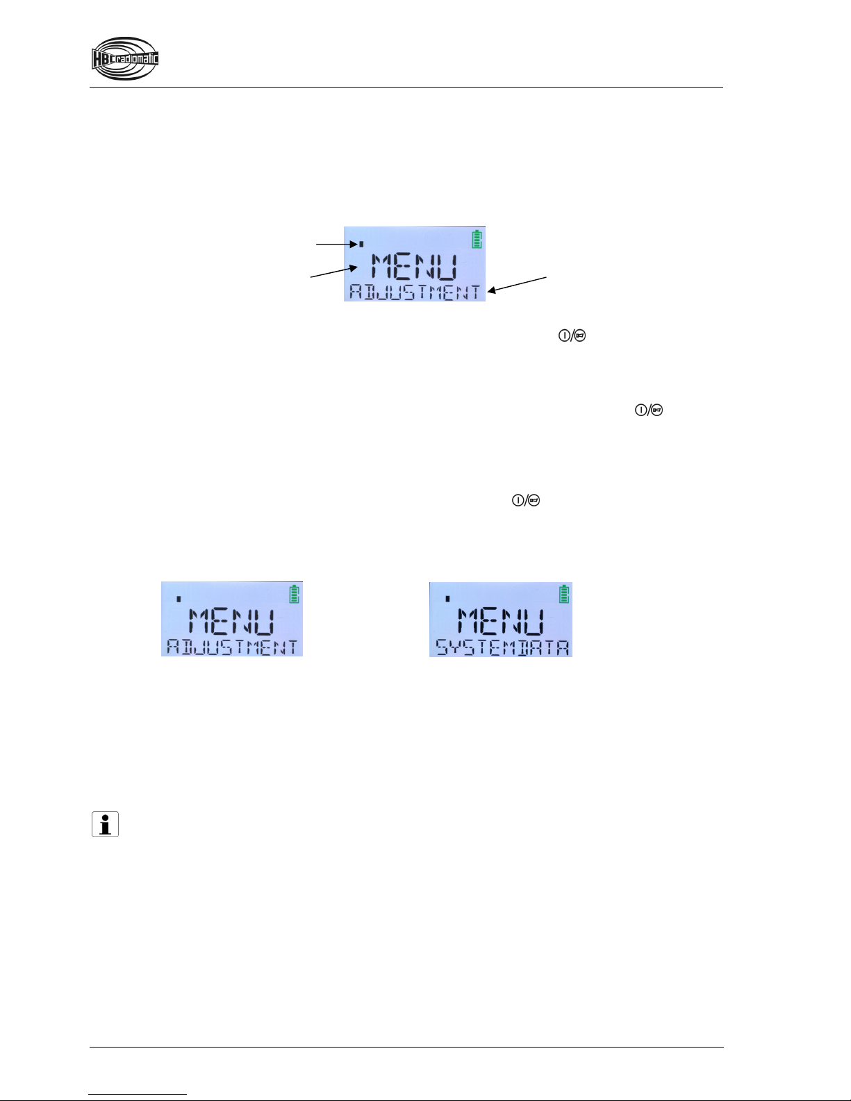
5. MENU ADJUSTMENT is now shown in the display. Release the button and the button on the
right side. You are now in the first menu level.
Version with HBC Smart Card
Perform the following steps in max. 4 seconds:
1. Press the button on the right side of the button in the
second step and keep it actuated.
2. Pull the STOP switch. APPLY SMART CARD is now shown in
the display.
3. Hold your HBC Smart Card to the lower end of the transmitter
(cf. illustration).
4. The status LED flashes green. MENU is shown in the first text
line, ADJUSTMENT in the second text line.
Release the button on the right side of the button. You are
now in the selection menu.
Basic functions
There are various menu levels available for entering individual settings. The level you are currently in is
displayed in the first text line (= the upper line). In addition, bars appear in the left corner over the text
line. The number of bars indicates the current menu level. By browsing with the navigation button, the
second text line can display the respective available sub-menus or the configurable fields.
The display navigation and the input of your settings are made via the 2-step button. This operating
element has two basic functions:
The first step enables browsing between sub-menus or (in the last level of the menu structure)
moving the cursor between the editable values and selecting the requested character. If the first
step is pressed continuously, the display browses through the sub-menus until the button is
released or pressed into the second step. If you momentarily press the button once in step 1, the
next sub-menu is selected.
The second step is used for menu selection and saving your settings.
All individual settings begin in the selection menu (the first text line here displays MENU). You can
return to the selection menu from all levels easily. Simply press the button in the second step for
longer than 2 seconds.
In the selection menu there are 2 sub-menus, which are shown in the second text line:
Sub-menu ADJUSTMENT
Here you can adjust the display brightness and change the fixed texts in lines 1 and 2 of the display.
Sub-menu SYSTEMDATA
Here you will find information about the radio system that can be useful in a service case (e.g.
fabrication number, service phone number, frequencies etc.). Individual settings are not possible!
Note:
If you want to work with the transmitter after finishing your settings, you need to deactivate the
transmitter via the STOP switch and reactivate it by the standard start-up sequence or your
HBC Smart Card. For safety reasons, changing directly from the settings mode to working mode is
not possible.
Current menu
Current menu level.
Here: Level 1. Selected sub-menu (further
sub-menus or configurable
fields can be displayed by
browsing).

Perform settings
After successfully turning on the transmitter, MENU is shown in the upper line
of the display. The sub-menu ADJUSTMENT is already selected in the lower
text line. If the sub-menu SYSTEMDATA is shown, press once in the first
step until the requested sub-menu ADJUSTMENT is displayed.
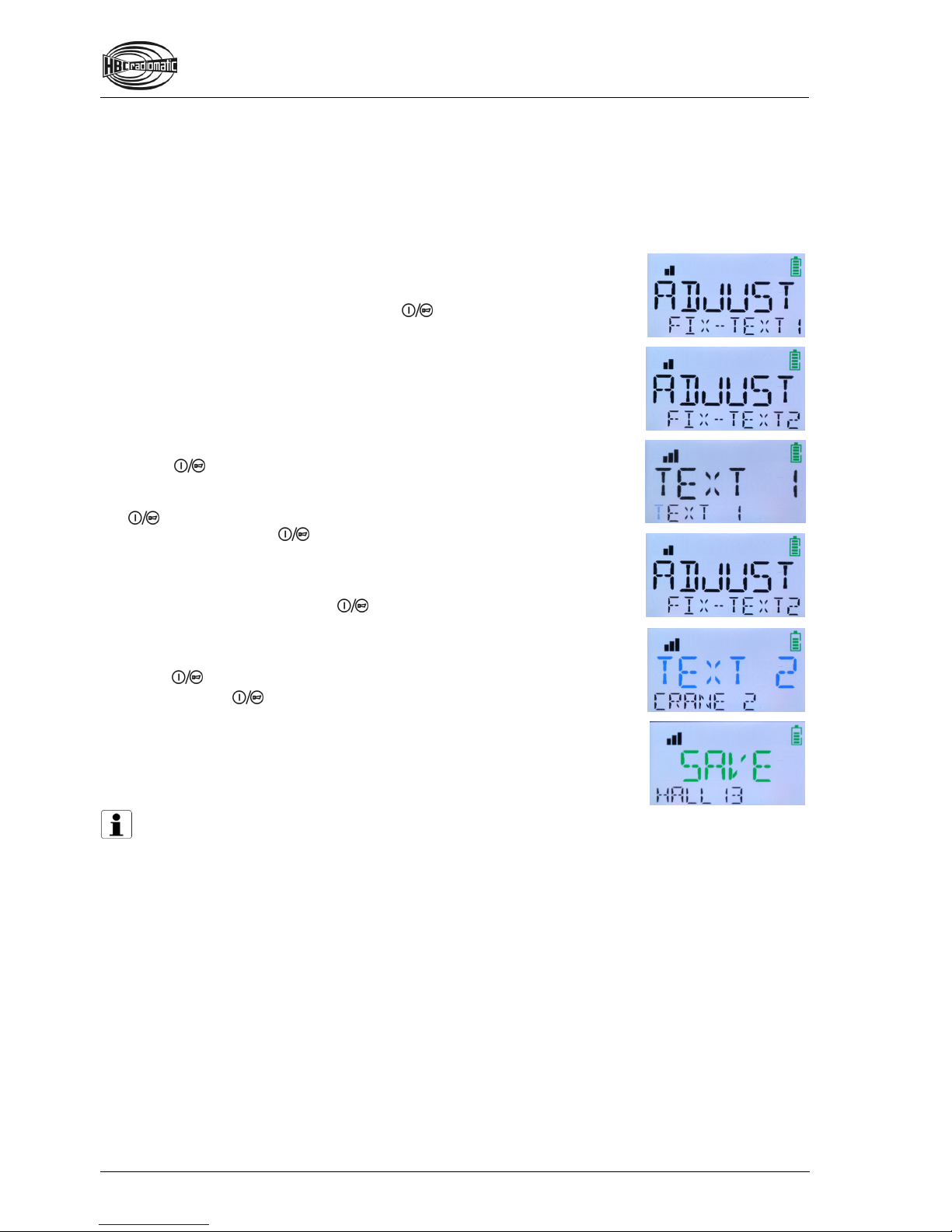
Now press in the second step. The sub-menu ADJUSTMENT is opened. ADJUST is displayed in
the upper text line.
Here you can choose between 3 sub-menus, which are displayed in the lower text line:
BRIGHTNESS Adjust display brightness
FIX-TEXT 1 Change text line 1
FIX-TEXT 2 Change text line 2
In case the sub-menus FIX-TEXT 1 and FIX-TEST 2 are not displayed, these setting possibilities have
not been ordered in your product version.
Set display brightness
Press in the first step until the sub-menu BRIGHTNESS is displayed.
In order to open the sub-menu, press in the second step.
BRIGHT is now displayed in text line 1. In line 2, an indication with some
squares flashes. The amount of squares indicates the
display brightness (more squares mean a brighter display).
Press in the first step until the desired brightness is set.
To save the desired brightness value, press in the second step.
The brightness is saved and the display returns to the menu ADJUST
BRIGHTNESS.
If you set an undesired brightness value by error, you can repeat this
procedure at any time.
Editing fixed text lines
In the settings mode you can edit the 2 text lines of the display. Text changes have to be performed
separately for each line respectively. Text line 1 contains 6 digits, line 2 contains 10. Each digit can
display both letters and numbers.
How to change texts:
From the selection menu, change to the ADJUSTMENT menu (cf. chapter “Perform settings”).
Browse through the sub-menus BRIGHTNESS, FIX-TEXT 1 and FIX-TEXT
2. In case you wish to edit text line 1 in the display, select the sub-menu
FIX-TEXT 1. If you wish to edit text line 2, select FIX-TEXT 2.
Open the desired sub-menu by pressing in the second step.
The display now shows the selected text line TEXT 1 or TEXT 2,
depending on which was selected. In the lower line you can see fields with
text, numbers or placeholders . This is the content that
has been displayed in the respective text line until now.
You can now edit each field individually (also fields with spaces) or enter
text or numbers in each empty field. To achieve this, navigate the cursor
with the first button step to the field you wish to change. The cursor’s
position is indicated by a blue flash of the respective field.
Press in the second step. The selected field flashes green and is
ready for editing.
The selection of the desired letter / number is done by the first step of the
button. Press the first button step until the desired digit appears. To
enter the digit, press in the second step. The digit selection for this
field is now completed. The next field flashes blue and again indicates the
cursor’s position.
Repeat these steps with all fields you wish to edit.
If you wish to abort, press in the second step for longer than
2 seconds. The display returns to the selection menu.
When you wish to save your entries, navigate the cursor with the first
button step to the TEXT 1 (or TEXT 2) indication.
Press in the second step. SAVE is now shown in the display.
To save, press again in the second step. Your settings are now stored
in the radio system. The display returns to the menu ADJUST
BRIGHTNESS.
If you wish to work with the radio control after successfully saving,
deactivate the transmitter via the STOP switch and reactivate the radio
system with the respective start-up procedure.
Note:
When saving, a bar graph indicates the advance of the saving process. Do not turn off the
transmitter if the saving process is not completed.

Retrieve system information
Here you can retrieve diverse pieces of information about the radio system that can be of high value in a
service case. The menu contains the following sub-menus:
Indication of the transmitter’s fabrication number (FSS)
Indication of the receiver’s fabrication number (FSE)
Indication of operating hours (HOURS)
Indication of the service phone number (CALL)
Show data
If you are not in the selection menu (= first menu level), change to this
menu now. To achieve this, press in the second step for longer than
2 seconds. MENU is now displayed. The lower text line automatically
displays the sub-menu ADJUSTMENT.
Change to the sub-menu SYSTEMDATA via the first step of the
button.
Press in the second step. The upper text line now shows FSS, the
lower line shows the transmitter’s fabrication number.
All further data can be retrieved via the first step of the button.
Please be aware that the service phone number is shown on two display
pages. The first page shows the text CALL SERVICE. You can see the
service number by again pressing .
To return to the selection menu, press in the second step for longer
than 2 seconds.
Battery and Battery Charger
NiMH Battery
The battery capacity (= the ability to store electric current) and the battery charge (= the actual amount
of stored current) depend on the age of the battery and the environment temperature. Older batteries
begin to lose capacity over time. If the temperatures are below 0 °C or above 40 °C, the charge
decreases faster.
Note:
In all cases, charge the batteries completely before initial use and at intervals not exceeding
6 months if they are stored. This ensures that the batteries have their full capacity in use,
even after long storage. Please refer to the date on the battery’s packaging.
Charge the battery fully before storing it for a prolonged period. Otherwise total discharge may
occur.
Use only the associated HBC charger to charge the battery
Charge the battery at an ambient temperature of 0 – 40 °C (32 – 104 °F).
Charge the battery only when the battery display flashes red, an acoustic signal sounds, the
status LED flashes red and the transmitter vibrates (option).
Always store rechargeable batteries at room temperature.
Protect the battery from short circuits and always store it in the protective cover provided.
When handled properly the battery can exceed 500 charging cycles
Battery Charger
Depending on customer selection, an AC or DC charger is available.
Ensure that you observe the following instructions:
Use this charger only to charge the batteries specified on the type plate.
The charger may not be used in hazardous areas.
The charger has to be operated with the voltage indicated on the back.
The charger has to be used in vehicles or indoors only.
Use the charger only within the specified temperature range.
Protect the charger against heat, dust and humidity.
Do not cover the charger while it is in use.
Disconnect the charger from the power supply when it is not in use.
In case of any fault of the charger or the connecting cable disconnect it immediately and put it
out of operation.
Do not make technical changes to the charger or the connecting cable.
Defects must be repaired by qualified personnel only.
Three LEDs indicate the actual operating state of the battery.
LED green: Illuminates when battery is charged.
LED orange: Illuminates when battery is charging.
LED red: Illuminates when battery is deep discharged or defective.
Note:
If a deep discharged battery is inserted into the charger, the red LED will illuminate for a few
seconds before charging is started (LED orange illuminates).

QA108600 / QD108300 / QD308300 with EC type-approval
The charger is supplied with a connecting cable with a matching power plug.
Charging the battery
1.Connect the charger via the connecting cable to the power supply.
2.Insert the battery into the compartment.
Charging will start automatically.
Technical Data
Operating voltage
100 – 240 V AC (QA108600)
10 – 30 V DC (QD108300 / QD308300)
Charging time ca. 3 h
Operating temperature 10 – 40 °C (50 – 104 °F)
Housing material Plastic
Protection class II

Options
The availability of the following functions depends on the design and configuration of your radio control
system.
Safety Features
radiomatic®shock-off / roll-detect / zero-g / inclination switch
The safety features enable a quick shut-down of the radio control in specific emergency situations.
Therefore, these intelligent functions prevent a dangerous unintended command from being given to the
crane or machine.
radiomatic®shock-off can trigger a quick automatic shut-down of the radio control in
case of an impact to the transmitter – e. g. if the transmitter is being hit by a massive
object thereby getting out of control.
radiomatic®roll-detect can automatically detect rolling of the transmitter and, in this
case, initiate a quick shut-down of the radio control.
radiomatic®zero-g can automatically detect if the transmitter is dropped or being
thrown to another user. In such cases, zero-g can trigger a quick automatic shut-down
of the transmitter.
inclination switch can deactivate the transmitter, if it exceeds an inclination angle of
approx. 130° – 170° for a certain time and/or if it is placed front side down.
When the transmitter was shut down with radiomatic®shock-off/roll-detect/zero-g or
inclination switch, the start button has to be activated until the status LED flashes
green. Then the transmitter is ready to operate again.
The safety features do not relieve the operator of his responsibility to turn off
the transmitter with the STOP switch when not in use.

radiomatic®infrakey
The radio system can only be activated via an infrared
link between the transmitter and the receiver. This
increases the safety of operation, i.e. the machine can
not become inadvertently enabled.
radiomatic®infrakey operates either with an infrared
module in the receiver housing (radiomatic®infrakey
internal) or with the offset infrared antenna focus I
(radiomatic®infrakey external).
To activate radiomatic®infrakey, actuate the start button
on the transmitter.
Function of radiomatic®infrakey with focus I
Notes:
The range of the infrared beam is max. 20 m (66 ft).
The angle of radiation is 30°.
The front panel of the receiver must be visible (only radiomatic®infrakey internal).
Joystick with Deadman Function
In order that it is possible to issue control commands the button integrated into the joystick must be
pressed before the joystick is moved. The function then reverts to self-locking and remains effective until
the joystick is back in the zero position. This enables the avoidance of potential risks through the
unintentional actuation of the joystick.
Vibration Alarm
With the vibration alarm, the operator can be informed of an impending need to change the battery
and/or potential dangers on the machine through the vibration of the transmitter. This information can be
for example pre-warnings for high wind speeds or threatening excess crane loads.
Front Panel Lighting
With the front panel lighting potential dangers resulting from incorrect operation, based on poor visibility,
can be prevented. The operator simply switches on multiple LEDs, which are integrated into the rollover
bar, with a switch or button on the transmitter.

Shut-off on Implausible Control Commands
The automatic shut-off will activate after a sequence of multiple questionable movement commands. If,
for example, one or more joysticks on the transmitter are actuated successively in different directions in
an irregular manner, the system switches off automatically.
This function protects the operator and the whole work environment from potential dangers as well as
the machine from wear resulting from rapid and erratic movements.
After an automatic switch-off you must reactivate the transmitter as described in chapter Operation.
Micro Drive
With the micro drive function the speed of the machine is limited to a preselected level. Even at full
movement of the joystick/linear lever, the operator can not exceed this speed limit. In this manner
demanding drive maneuvers can be managed and inexperienced users can be protected from potential
dangers that can result from “speeding”.
Orthogonal Drive (Electronic Cross Gate)
With the orthogonal drive function dangerous situations, caused by unintentional diagonal movements
are being prevented. The operator will have to return the joystick back to zero position before another
directional command can be activated. This function is suitable for example for situations where the
operator has to make precision commands in confined areas. Diagonal movements are not possible.
User identification
The "user identification" function with the HBC Smart Card enables a simple personalization of the radio
system as well as the storage of all user profiles in the radio system. Safety relevant functions can be
released to authorized personnel only and unauthorized users can be protected of potentially dangerous
situations. In addition the radio system can store user-related all operating processes as well as the
respective on time of the radio system. This data can be read from the radio system and shows how long
the radio system was in use and how the individual operators used the various functions of the radio
system.

Frequency Management
Fixed Frequency
If the identification plate in the battery compartment of the transmitter shows a frequency value (e.g.
433,500 MHz), the transmitter operates with a fixed frequency.
Please contact you service department if the frequency has to be changed because the radio channel is
already assigned to another user.
Frequency Selection via Scanner
Transmitter and receiver are equipped with four frequencies (refer to wiring diagrams).
If the radio channel is occupied, you can switch to another radio channel by using the rotary switch on
the transmitter. The scanner in the receiver automatically resets the transmitter to the new frequency
selected within one second.
Manual Frequency Switching
If the identification plate in the battery compartment of the transmitter shows the label man, the
transmitter features manual frequency switching.
This function can be used to change the radio channel during radio operation.
Actuate the start button into the first step until an acoustic signal sounds. Then release the button.
Please contact your service department if all available frequencies are occupied.
radiomatic® AFS
If the identification plate in the battery compartment of the transmitter shows the label AFS, the
transmitter is equipped with radiomatic®AFS (Automatic Frequency Selection).
When activating the transmitter radiomatic®AFS will check if the present radio channel is free. If the
radio channel is occupied, the system automatically finds and saves a free radio channel.
If the radio channel currently in use is occupied by another radio control system, you must switch the
transmitter off and on again in order to allow radiomatic®AFS to switch to a free radio channel.
The radiomatic®AFS option also includes the manual frequency switching function.
Note:
If radiomatic®AFS is to perform optimally, all the other radio systems in the immediate working
environment (e.g. the factory hall or building site) should be switched on before starting to use the
radio system for the first time. This allows radiomatic®AFS to detect automatically which radio
channels are already being used in the working area, and thereby to choose a suitable free
channel for its own use.
In addition, when switching the radio system on for the first time, the user should make sure that
his distance from the radio receiver and from the machine is a realistic reflection of the working
situation.
radiomatic® AFM
If the identification plate in the battery compartment of the transmitter shows the label AFM the
transmitter is equipped with radiomatic®AFM (Automatic Frequency Management).
radiomatic®AFM detects available radio channels constantly. If the radio channel currently in use is
occupied by another radio control system, radiomatic®AFM switches automatically to a free radio
channel.

Catch-Release
Via the Catch-Release option two or more transmitters can control a
machine alternately.
When the receiver is switched on, the machine can initially be
controlled via any associated transmitter. Once the receiver was taken
over by one transmitter, the other transmitters no longer have access.
Take over machine
1.Switch the transmitter on.
2.Enter the "Catch" command on the transmitter and actuate the
start button.
The access rights for the machine remain with that transmitter until the
"Release" command is issued by that transmitter.
Release machine
1.Enter the "Release" command on the transmitter.
2.Switch the transmitter off.
The access rights for the machine are cancelled. Machine control can be taken over by another
transmitter.
Operating Example:
Transmitter 1 has taken over the machine. Transmitter 2 is to be given control.
1.Enter the "Release" command on transmitter 1.
2.Switch transmitter 1 off.
3.Switch transmitter 2 on.
4.Enter the "Catch" command on transmitter 2 and actuate the start button.
Transmitter 2 now has sole access to all machine functions.
Notes:
If a receiver has already been adopted by a transmitter can be displayed via a lamp on the
machine.
If the operating voltage of the receiver fails, the receiver returns to the starting condition in
which it can be adopted by any transmitter. If necessary, the receiver must be adopted anew.
If the transmitter is deactivated without the command "Release" having been issued, the other
transmitters have no access to the receiver. The starting condition described above can only
be resumed by deactivating the operating voltage at the receiver.
Table of contents
Other HBC Receiver manuals


