Standex RGM23 Manual
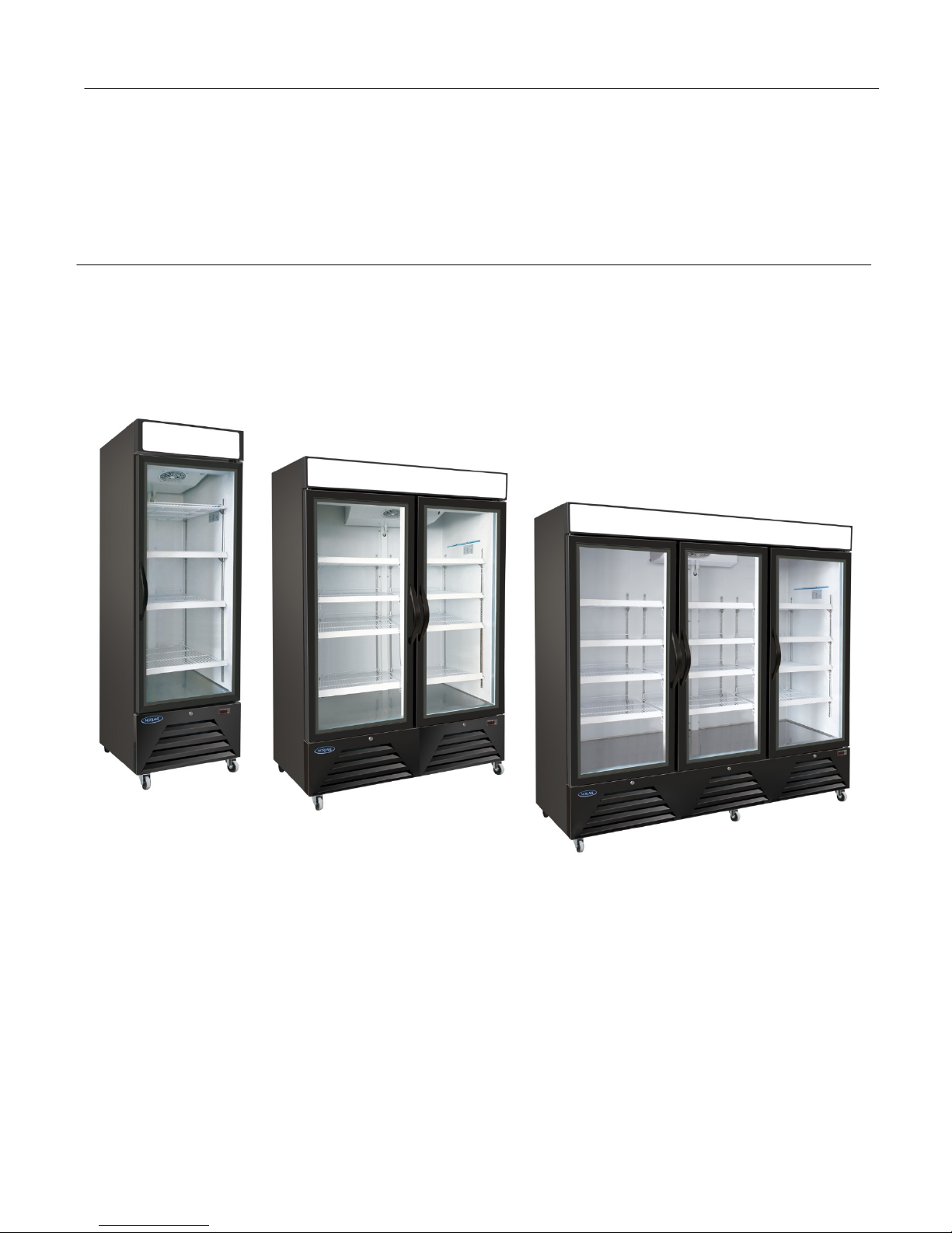
GLASS DOOR
REFRIGERATED MERCHANDISER
Installation, Operation and Maintenance Instructions
Models RGM23, RGM48 and RGM72
2 11/18 161744
TABLE OF CONTENTS
INTRODUCTION ...............................................................................................................................................................3
STORE CONDITIONS.......................................................................................................................................................3
WARNING LABELS AND SAFETY INSTRUCTIONS .....................................................................................................4
PRE-INSTALLATION INSTRUCTIONS ...........................................................................................................................5
Inspection for Shipping Damage.................................................................................................................................5
INSTALLATION INSTRUCTIONS....................................................................................................................................5
Uncrating ....................................................................................................................................................................5
Shelving Installation....................................................................................................................................................5
Location .....................................................................................................................................................................5
Electrical Supply .........................................................................................................................................................5
Initial Cleaning ............................................................................................................................................................6
OPERATION .....................................................................................................................................................................6
Set-Up.........................................................................................................................................................................6
Lights .........................................................................................................................................................................6
Temperature Control ..................................................................................................................................................6
Defrost ........................................................................................................................................................................6
MAINTENANCE ................................................................................................................................................................6
Surface Cleaning ........................................................................................................................................................6
Door Gasket................................................................................................................................................................6
Doors/Hinges ..............................................................................................................................................................7
Condenser Cleaning ..................................................................................................................................................7
Notice to Store Owners/Managers..............................................................................................................................7
Electrical .....................................................................................................................................................................7
PARTS LIST......................................................................................................................................................................8
SALE AND DISPOSAL.....................................................................................................................................................9
WIRING DIAGRAM .........................................................................................................................................................10

3 11/18 161744
INTRODUCTION
This manual contains important instructions for installing, using, and servicing a Refrigerated Merchandiser case.
Read all these documents carefully before installing or servicing your equipment.
STORE CONDITIONS
The Refrigerated Merchandiser cases are designed to operate best in the controlled environment of an air-
conditioned store. The store temperature should be at or below +75°F and a relative humidity of 55% or less. At higher
temperature or humidity conditions, the performance of these cases may be affected and the capacity diminished.
The Refrigerated Merchandiser should not be positioned where it is directly exposed to rays of sun or near a direct
source of radiant heat or airflow. This will adversely affect the case and will result in poor performance.
If this case is to be located against a wall, there must be at least 2” space between the wall and the back of the case.
This space will allow for the circulation of air behind the case and extend the life of the unit.
NOTICE
Read this manual before installing your cabinet. Keep the manual and refer to it before
doing any service on the equipment. Failure to do so could result in personal injury or
damage to the cabinet.
DANGER
Improper or faulty hook-up of electrical components on the refrigeration units can result
in severe injury or death.
All electrical wiring hook-ups must be done in accordance with all applicable local, regional or
national standards.
NOTICE
Installation and service of the refrigeration and electrical components of the cabinet
must be performed by a refrigeration mechanic and/or a licensed electrician.
The portions of this manual covering refrigeration and electrical components contain technical instructions intended
only for persons qualified to perform refrigeration and electrical work.
This manual cannot cover every installation, use or service situation. If you need additional information, call the
Customer Service Department.
4 11/18 161744
WARNING LABELS AND SAFETY INSTRUCTIONS
This symbol is the safety-alert symbol. When you see this symbol on your cabinet or in this
manual, be alert to the potential for personal injury or damage to your equipment.
Be sure you understand all safety messages and always follow recommended precautions and safe operating
practices.
NOTICE TO EMPLOYERS
You must make sure that everyone who installs, uses or services your cabinet is
thoroughly familiar with all safety information and procedures.
Important safety information is presented in this section and throughout the manual. The following signal words are
used in the warnings and safety messages:
DANGER: Severe injury or death will occur if you ignore the message.
WARNING: Severe injury or death can occur if you ignore the message.
CAUTION: Minor injury or damage to your cabinet can occur if you ignore the message.
NOTICE: This is important installation, operation or service information. If you ignore the
message, you may damage your cabinet.
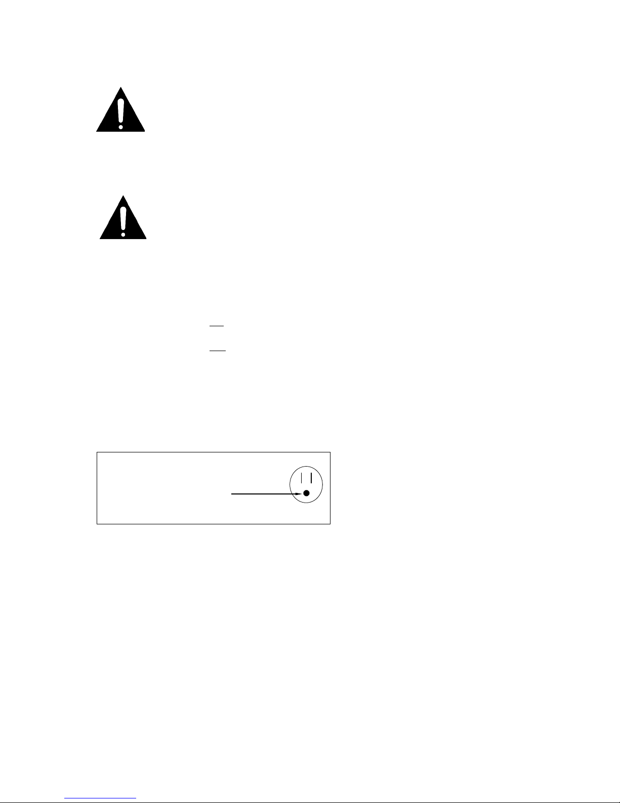
WARNING!
GROUND REQUIRED
FOR SAFE OPERATION

5 11/18 161744
PRE-INSTALLATION INSTRUCTIONS
INSPECTION FOR SHIPPING DAMAGE
Inspect all cartons and crates for damage as soon as they arrive. If damage is noted to shipping crates or cartons or
if a shortage is found, note this on the bill of lading (all copies) prior to signing. The receiving party is responsible for
filing all freight claims with the delivering truck line.
If damage is discovered when the cabinet is uncrated, immediately call the delivering truck line and follow up the call
with a written report indicating concealed damage to your shipment. Ask for an immediate inspection of your concealed
damage item. Crating material must be retained to show the inspector from the truck line.
INSTALLATION INSTRUCTIONS
This cabinet should be uncrated, set up and installed by competent service people.
Warning!– This cabinet uses a flammable refrigerant. Use caution with handling, moving and maintaining this
cabinet to avoid either damaging the refrigerant tubing or increasing the risk of a refrigerant leak.
Uncrating
Remove the protective covering (banding, shrink wrap, cardboard, plywood inner liners) and set aside. The cabinet is
nested on the shipping pallet with L shaped metal brackets on each side. Remove the metal brackets from the pallet and the
cabinet (screws). Using a team of assistants, slide the cabinet off the pallet.
WARNING - The cabinet has Casters installed on the base and will be unstable until all four casters are on the floor. Use
caution when sliding the unit off the pallet so the unit does not tip. Use a team of at least three to remove the cabinet from the
pallet.
Inside the cabinet you will find Shelves, Shelf Clips and a literature package.
Shelving Installation
The unit comes with Shelves and Shelf Supports. The Shelf Supports clip into the Pilaster Strips on the inside walls
of the unit and the Shelf then sits on the Shelf Supports. Four Shelf Supports are supplied for each Shelf. The Shelves
can be installed at any height to suit your needs and are adjustable in 1/2” height increments. The shelves come with
Product Identification Strips that can be attached to the front edge of the shelves. The Product Identification Strips will
accept pricing and product descriptor tags to suit your requirements.
Location
NOTICE! The refrigeration system located at the bottom of the unit requires free air access for proper operation. Allow
a minimum of 2” between the back of the unit and the wall.
Do not locate next to heat generating equipment or in direct sunlight.
Make sure that the cabinet is level to allow for proper drainage of condensate water.
Confirm that the floor is capable of supporting the weight of the cabinet and its contents.
This unit is intended for indoor use only.
Electrical Supply
WARNING! To prevent electrical shock and fire be sure the unit is properly grounded.
Confirm that the electrical supply has the correct voltage, frequency and current carrying capacity for the requirements
of the unit (see data plate on inside of unit). The unit should be isolated on a circuit. Do not use an extension cord to
get power to the unit. Improper installations will void the compressor warranty.

6 11/18 161744
Initial Cleaning
Keep the equipment clean and sanitary so it will meet your local sanitation codes. Clean the cabinet with a mild
detergent and water, then rinse to remove any residual manufacturing oils. Do not use any chlorine based cleaners
on the stainless steel.
OPERATION
Set-Up
When loading the unit with product take care not to block the flow of air that could result in poor performance. Do not
push product all the way to the back wall as cold air is intended to flow down the back wall to the floor of the unit and
return to the top.
Do not completely fill the unit with warm product as it will take an extended time to cool.
Rotate stock regularly to prevent the accumulation of old stock. Use a first-in / first-out system.
The shelves have a load capacity of 100 pounds per shelf. Do not overload the shelves.
Do not load product within 3” of the top of the unit for proper operation.
Lights
The interior cabinet and display sign lights are controlled via an on/off switch on the front of the unit under the top
facade.
Temperature Control
The Temperature Control is located behind the Lower Front Grill of the unit. It will display the current air temperature
inside the cabinet.To adjust the setting of the Temperature Control, first remove the Lower Front Grill (remove 2
screws and lift off), then turn the control knob clockwise for colder and counter-clockwise for warmer temperatures.
Allow the cabinet a couple of hours to reach the new temperatures. The cabinet will hold temperatures of approximately
42°F at a set point of #1, 38°F at setting #5 and 34°F at setting #9.
Defrost
The Refrigerated Merchandiser relies on Off Cycle defrost with an addition defrost programmed into the Temperature
Control that will shut the refrigeration system down every 6 hours for 20 minutes to facilitate a complete defrost.
MAINTENANCE
Warning! This cabinet uses a flammable refrigerant. All service should be done by factory authorized service
personnel using original equipment parts to minimize the risk of possible ignition due to incorrect replacement parts or
improper service.
Surface Cleaning
The interior and exterior can be cleaned using soap and warm water. Always rinse thoroughly after cleaning. Do not
use an abrasive cleaner as it will scratch the surface.
When cleaning stainless steel cleaning solutions need to be alkaline based or non-chlorinated. Any cleaner containing
chlorides will damage the protective layer of the stainless steel. Chlorides are commonly found in hard water, salts
and household and industrial cleaners. If cleaners with chlorides are used be sure to rinse repeatedly and dry
thoroughly.
Routine cleaning of stainless steel can be done with soap and water. Extreme stains or grease should be cleaned with
a non-abrasive cleaner and plastic scrub pad. Always rub with the grain of the steel.
Door Gasket
Gaskets require regular cleaning to prevent mold and mildew build up and also to keep the elasticity of the gasket.
Cleaning can be done with the use of warm soapy water. Avoid full strength cleaning products on gaskets as this can
cause them to become brittle and prevent proper seals. Never use sharp tools to scrape or clean the gasket which
could possibly tear the gasket and rip the bellows.
7 11/18 161744
Door Gaskets can easily be replaced without the use of tools. The gaskets are dart style so they can be pulled out of
the groove in the door and replaced by pressing the new gasket back into the groove.
Doors/Hinges
Should a door become out of alignment with the unit it can be straightened out by loosening the screws that hold the
hinges, straightening the door and retightening the hinge screws.
Condenser Cleaning
The Condenser Coil is located behind the Lower Front Grill. Always disconnect the unit from power prior to performing
any maintenance procedures including cleaning the Condenser Coil. The Condenser Coil requires regular cleaning.
Recommended cleaning is every 3 months. In some instances you may find that there is a large amount of debris and
dust or grease accumulated on the coil prior to the 3 month period. In these cases the coil should be cleaned every 1
month.
If the build-up on the coil consists of only light dust and debris, the coil can be cleaned with a simple brush. Heavier
dust build-up may require a vacuum or compressed air to clean the coil. If heavier grease is present there are
degreasing agents available specifically for cleaning condenser coils.
Failure to maintain a clean Condenser Coil can cause high temperatures and excessive run times. Continuous
operation with a dirty or clogged coil can result in Compressor failures. Neglecting the Condenser Coil cleaning
procedures will void any warranties associated with Compressor failure.
NOTICE TO STORE OWNERS / MANAGERS
CAUTION! Moisture or liquid around or under the cabinet is a potential slip/fall hazard for persons walking by
or working in the general area of the cabinet. Any cabinet malfunction or housekeeping problem that creates
a slip/fall hazard around or under the cabinet should be corrected immediately.
If moisture or liquid is observed around or under the cabinet, an immediate investigation should be made by qualified
personnel to determine the source of the moisture or liquid. The investigation should determine if the cabinet is
malfunctioning or if there is a drainpipe leaking.
ELECTRICAL
WARNING
Before servicing electrical components in the case or the doors or door frames make sure all
power to case is off. Always use a qualified technician.
Check voltage and amps drawn to determine proper line and fuse or circuit breaker size. Check power supply for low
voltage. If voltage reads 120 with no load, and it drops below 104 when the compressor tries to start, it is an indication
of too small supply wiring or too long of run.
It is recommended that a separate circuit be run for each cabinet to prevent another appliance blowing the fuse or
breaker, causing loss of product.
The cabinet must be grounded.
8 11/18 161744
PARTS LIST
The table below gives replacement part numbers. Use this chart when ordering replacement parts for your cabinets.
Always Advise Cabinet Model and Serial Number When Ordering Parts
MODEL
Part Description
RGM23
RGM48
RGM72
Compressor (includes electricals)
161658
161659
161660
Compressor Electrical Kit (Overload,Relay, Capacitor,..)
161661
161662
161663
Condenser Fan Motor
161664
161664
161665
Condenser Fan Blade
161666
161666
161667
Condenser Fan Bracket
161668
161668
161669
Condenser Coil
161670
161670
161671
Drier
161672
161672
161672
Capillary Tube
161673
161674
161675
Heat Exchanger-cap tube/suction line (Cabinet/Mach. Comp.)
161676/161679
161677/161680
161678/161681
Evaporator Coil
161682
161683
161684
Evaporator Fan Motor
161685
161686
161687
Evaporator Fan Blade
161688
161689
161689
Evaporator Fan Motor Assy (motor, blade, bracket)
161690
161691
161692
Evaporator Panel W/Fan Guard
161693
161694
161694
Condensate Pan (w/o hot gas loop)
161695
161695
161695
Temperature Control Assy (with display and sensors)
161696
161696
161696
Temperature Control Sensor Kit (includes both sensors)
161697
161697
161697
Light Power Switch
161698
161698
161698
LED Light Driver
161699
161670
161670
LED Sign Light
161701
161702
161703
LED Door Light
161704
161704
161704
Shelf
161705
161706
161706 Ends/161707 Center
Shelf Product Identifier Strip
161708
161709
161709
Shelf Support Clip
161710
161710
161710
Pilaster
161711
161711
161711
Lower Front Grill
161712
161713
161714
Rear Grill
161715
161716
161717
Door Lock w/Key
161718
161718
161718
Terminal Block
161719
161719
161719
Door Switch Assy
161720
161720
161720
Advertising Panel Assy
161721
161722
161723
Door Assy RH
161724
161724
161724
Door Assy LH
161725
161725
161725
Door Hinge Top Right
161726
161726
161726
Door Hinge Top Left
161727
161727
161727
Door Hinge Bottom Right
161728
161728
161728
Door Hinge Bottom Left
161729
161729
161729
Door Gasket
161730
161730
161730
Evaporator Drain Pan
161731
161732
161732
Caster Kit (3.63 OAH) set of 2
161733
161733
161733
Power Cord
161734
161734
161734

9 11/18 161744
SALE AND DISPOSAL
OWNER RESPONSIBILITY
If you sell or give away your cabinet; you must make sure that all safety labels and the IOM Instructions are
included with it. If you need replacement labels or manuals, contact the Customer Service Department and we will
provide them at no charge.
The Customer Service Department should be contacted at the time of sale or disposal of your cabinet so records
may be kept of its new location.

10 11/18 161744
This manual suits for next models
2
Table of contents
Other Standex Merchandiser manuals


Popular Merchandiser manuals by other brands

Hussmann
Hussmann Impact C2-LGE Technical data sheet

Hussmann
Hussmann SMBT Technical data sheet

Hatco
Hatco Glo-Ray GRDW-2 Installation & operating manual

Hussmann
Hussmann IMPACT Elite E3 datasheet

Hussmann
Hussmann Impact Excel M3X-EP Technical data sheet

Polar Refrigeration
Polar Refrigeration GC872-A instruction manual


Global Solutions
Global Solutions GS1400-25 user manual

Alto-Shaam
Alto-Shaam HSM-24/3S/T Operator's manual

Federal
Federal SQ3HD Installation & operation instructions

Blizzard
Blizzard GD350 Original instructions

Hussmann
Hussmann IMPACT D5RRI Parts installation and removal guide

Hussmann
Hussmann CGDM install guide