Stanley 07535 User manual

INSTRUCTION MANUAL
ORIGINAL INSTRUCTION
07535 Pantograph Workstation for Speed Rivets
Hydro-Pneumatic Power Tool
EN
Hydro-Pneumatic Pantograph Workstation for Speed Rivets
BG
Хидропневматична пантографна работна станция за бързи нитове
HR
Hidro-pneumatska pantografska radna postaja za brze zakovice
CZ
Hydropneumatická pantografová pracovní stanice pro rychlostní nýtování
RO
Staţie de lucru hidro-pneumatică pantograf pentru nituri rapide
HU
Hidropneumatikus áramszedős munkaállomás gyorsszegecsekhez
SK
Hydropneumatická pantografová pracovná stanica na rýchle umiestňovanie nitov
SL
Hidro-pnevmatska pantografska delovna postaja za hitrostne kovice 07535
RU
Гидропневматическая рабочая станция с пантографом для заклепок скоростной
установки
AR
ﻡﺡﻁﺓ ﺍﻝﻉﻡﻝ ﺍﻝﻩﻱﺩﺭﻭ ﻩﻭﺍﺉﻱﺓ ﻝﻥﺱﺥ ﺍﻝﺏﺭﺍﺵﻱﻡ ﺍﻝﺱﺭﻱﻉﺓ
LV
Ātro kniežu hidropneimatiskā pantogrāfa darbstacija
LT
Hidraulinės-pneumatinės kniedijimo staklės su pantografu
ET
Hüdropneumaatiline pantograaf kiirneetide paigaldamiseks
EL
Υδρο-πνευματικός παντογραφικός σταθμός εργασίας για πριτσίνια ταχείας τοποθέτησης
TR
Hızlı Perçinler için Hidro Pnömatik Pantograf İş İstasyonu

CONTENT
1. SAFETY DEFINITIONS ................................................................................................................................................... 2
1.1 GENERAL SAFETY RULES .......................................................................................................................................................................... 2
1.2 PROJECTILE HAZARDS .............................................................................................................................................................................. 2
1.3 OPERATING HAZARDS............................................................................................................................................................................... 3
1.4 REPETITIVE MOTIONS HAZARDS............................................................................................................................................................ 3
1.5 ACCESSORY HAZARDS .............................................................................................................................................................................. 3
1.6 WORKPLACE HAZARDS............................................................................................................................................................................. 3
1.7 NOISE HAZARDS.......................................................................................................................................................................................... 3
1.8 ADDITIONAL SAFETY INSTRUCTIONS FOR PNEUMATIC AND HYDRAULIC TOOL ................................................................ 4
2. SPECIFICATIONS............................................................................................................................................................ 5
2.1 TOOL SPECIFICATION................................................................................................................................................................................. 5
3. INTENT OF USE.............................................................................................................................................................. 6
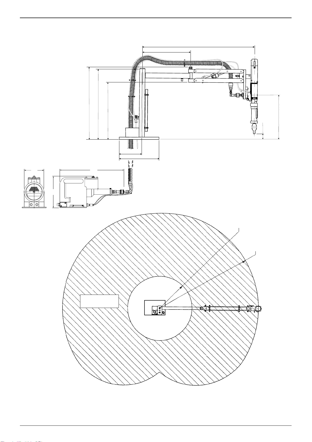
3.1 TOOL DIMENSIONS - 07535 MKII MODEL........................................................................................................................................... 7
4. PUTTING INTO SERVICE................................................................................................................................................ 8
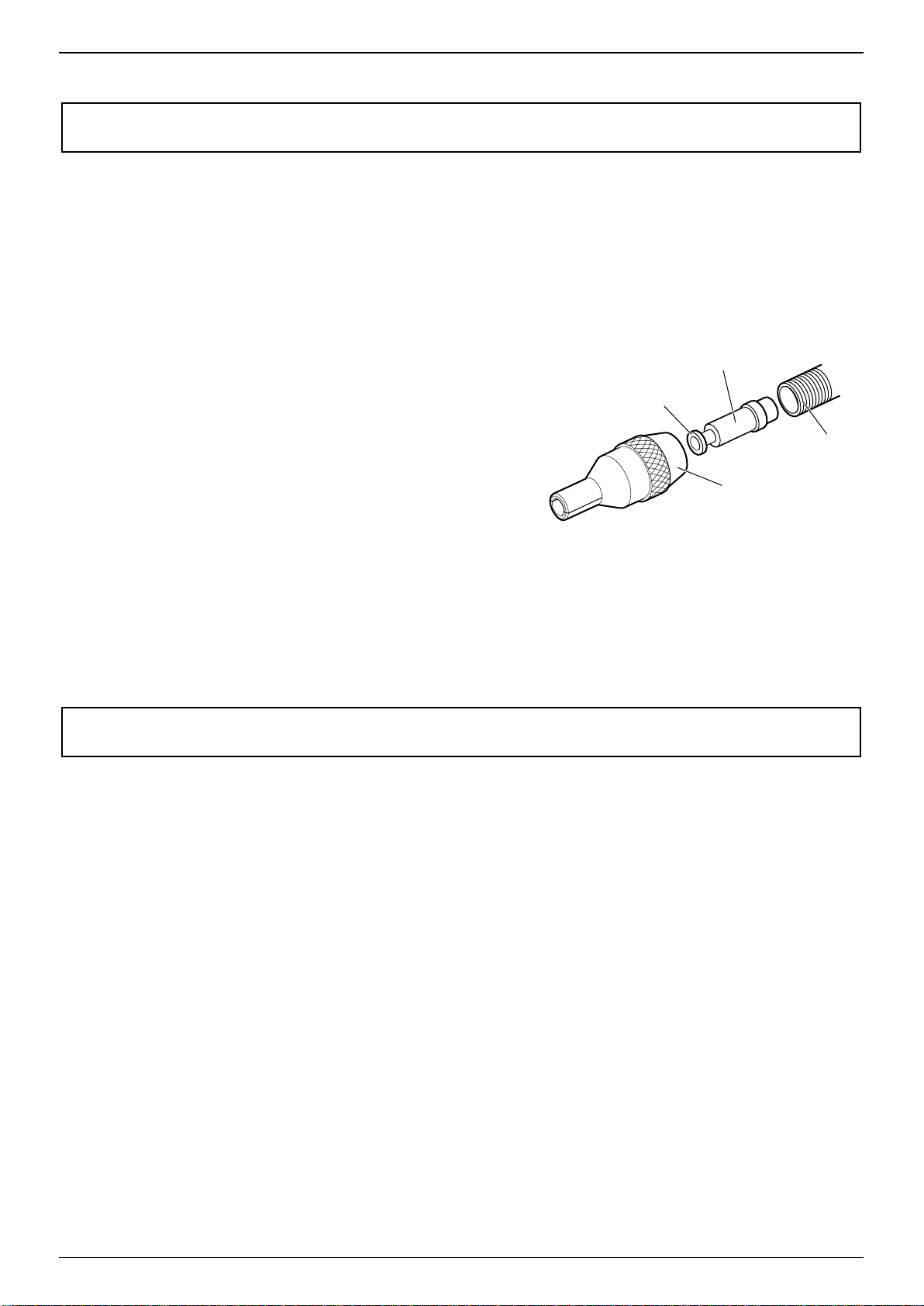
4.1 AIR SUPPLY .................................................................................................................................................................................................... 8
4.2 CURSOR .......................................................................................................................................................................................................... 9
4.3 LOADING AND RELOADING THE TOOL................................................................................................................................................ 9
4.4 OPERATING PROCEDURE........................................................................................................................................................................10
4.5 PLACING EQUIPMENT..............................................................................................................................................................................10
5. SERVICING THE TOOL..................................................................................................................................................11
5.1 DAILY/ WEEKLY...........................................................................................................................................................................................11
5.2 MOLY LITHIUM GREASE EP 3753 SAFETY DATA..............................................................................................................................11
5.3 SERVICE KIT..................................................................................................................................................................................................12
6. MAINTENANCE............................................................................................................................................................13
6.1 DISMANTLING 07535-02500 MK II......................................................................................................................................................13
6.2 GENERAL ASSEMBLY OF BASE TOOL 07535-02500 MKII.............................................................................................................15
6.3 PARTS LIST FOR BASE TOOL 07535-02500 MKII..............................................................................................................................16
6.4 GENERAL ASSEMBLY OF PANTOGRAPH ARM..................................................................................................................................17
6.5 PARTS LIST FOR PANTOGRAPH ARM ..................................................................................................................................................18
6.6 INTENSIFIER 07531-02200 - MAINTENANCE....................................................................................................................................19
6.7 INTENSIFIER 07531-02200......................................................................................................................................................................20
6.8 INTEGRAL HANDLE AND TRIGGER ASSEMBLY ................................................................................................................................21
6.9 PILOT VALVE 07005-00590 - MAINTENANCE ...................................................................................................................................23
6.10 PROTECTING THE ENVIRONMENT.......................................................................................................................................................23
7. PILOT VALVE 07005-00590.........................................................................................................................................24
8. PRIMING ......................................................................................................................................................................25
8.1 OIL DETAILS.................................................................................................................................................................................................25
8.2 PRIMING PROCEDURE..............................................................................................................................................................................25
9. FAULT DIAGNOSIS.......................................................................................................................................................26
10. EC DECLARATION OF CONFORMITY..........................................................................................................................27
11. UK DECLARATION OF CONFORMITY .........................................................................................................................28
12. PROTECT YOUR INVESTMENT! ...................................................................................................................................29
©2021 Stanley Black & Decker inc.
All rights reserved.
The information provided may not be reproduced and/or made public in any way and through any means (electronically or
mechanically) without prior explicit and written permission from STANLEY Engineered Fastening. The information provided
is based on the data known at the moment of the introduction of this product. STANLEY Engineered Fastening pursues a
policy of continuous product improvement and therefore the products may be subject to change. The information provided
is applicable to the product as delivered by STANLEY Engineered Fastening. Therefore, STANLEY Engineered Fastening
cannot be held liable for any damage resulting from deviations from the original specications of the product.
The information available has been composed with the utmost care. However, STANLEY Engineered Fastening will not
accept any liability with respect to any faults in the information nor for the consequences thereof. STANLEY Engineered
Fastening will not accept any liability for damage resulting from activities carried out by third parties. The working names,
trade names, registered trademarks, etc. used by STANLEY Engineered Fastening should not be considered as being free,
pursuant to the legislation with respect to the protection of trademarks.
ORIGINAL INSTRUCTION ENGLISH
1

This instruction manual must be read by any person installing or operating this tool with particular attention to the
following safety rules.
Always wear impact-resistant eye protection during operation of the tool. The grade of protection required should
be assessed for each use.
Use of the tool can expose the operator’shands to hazards, including crushing, impacts, cuts and abrasions and
heat. Wear suitable gloves to protect hands.
Use hearing protection in accordance with employer’sinstructions and as required by occupational health and
safety regulations.
1. SAFETY DEFINITIONS
The denitions below describe the level of severity for each signal word. Please read the manual and pay attention to these
symbols.
DANGER: Indicates an imminently hazardous situation which, if not avoided, will result in death or serious injury.
WARNING: Indicates apotentially hazardous situation which, if not avoided, could result in death or serious injury.
CAUTION: Indicates apotentially hazardous situation which, if not avoided, may result in minor or moderate injury.
CAUTION: Used without the safety alert symbol indicates apotentially hazardous situation which, if not avoided, may
result in property damage.
Improper operation or maintenance of this product could result in serious injury and property damage. Read and
understand all warnings and operating instructions before using this equipment. When using power tools, basic safety
precautions must always be followed to reduce the risk of personal injury.
SAVE ALL WARNINGS AND INSTRUCTIONS FOR FUTURE REFERENCE
1.1 GENERAL SAFETY RULES
• For multiple hazards, read and understand the safety instructions before installing, operating, repairing, maintaining,
changing accessories on, or working near the tool. Failure to do so can result in serious bodily injury.
• Only qualied and trained operators must install, adjust or use the tool.
• DO NOT use outside the design intent of placing STANLEY Engineered Fastening Blind Rivets.
• Use only parts, fasteners, and accessories recommended by the manufacturer.
• DO NOT modify the tool. Modications can reduce the eectiveness of safety measures and increase the risks to the
operator. Any modication to the tool undertaken by the customer will be the customer’sentire responsibility and void
any applicable warranties.
• Do not discard the safety instructions; give them to the operator.
• Do not use the tool if it has been damaged.
• Prior to use, check for misalignment or binding of moving parts, breakage of parts, and any other condition that aects
the tool’soperation. If damaged, have the tool serviced before using. Remove any adjusting key or wrench before use.
• Tools shall be inspected periodically to verify that the ratings and markings required by this part of ISO 11148 are legibly
marked on the tool. The employer/user shall contact the manufacturer to obtain replacement marking labels when
necessary.
• The tool must be maintained in asafe working condition at all times and examined at regular intervals for damage
and function by trained personnel. Any dismantling procedure will be undertaken only by trained personnel. Do not
dismantle this tool without prior reference to the maintenance instructions.
1.2 PROJECTILE HAZARDS
• Disconnect the tool from the air supply before performing any maintenance, attempting to adjust, t or remove a nose
assembly or accessories.
• Be aware that failure of the workpiece or accessories, or even of the inserted tool itself can generate high-velocity
projectiles.
• Always wear impact-resistant eye protection during operation of the tool. The grade of protection required should be
assessed for each use.
• The risks to others should also be assessed at this time.
• Ensure that the workpiece is securely xed.
• Check that the means of protection from ejection of fastener and/or mandrel is in place and is operative.
• Warn against the possible forcible ejection of mandrels from the front of the tool.
• DO NOT operate atool that is directed towards any person(s).
ENGLISH ORIGINAL INSTRUCTION
2

1.3 OPERATING HAZARDS
• Use of the tool can expose the operator’shands to hazards, including crushing, impacts, cuts and abrasions and heat.
Wear suitable gloves to protect hands.
• Keep tool handles dry, clean, and free from oil and grease.
• Maintain abalanced body position and secure footing when operating the tool.
• Release the start-and-stop device in the case of an interruption of the hydraulic supply.
• Use only lubricants recommended by the manufacturer.
• Contact with hydraulic uid should be avoided. To minimise the possibility of rashes, care should be taken to wash
thoroughly if contact occurs.
• Material Safety Data Sheets for all hydraulic oils and lubricants is available on request from your tool supplier.
• Avoid unsuitable postures as it is likely for these positions not to allow counteracting of normal or unexpected
movement of the tool.
• If the tool is xed to asuspension device, make sure that the xation is secure.
• Beware of the risk of crushing or pinching if nose equipment is not tted.
• DO NOT operate tool with the nose casing removed.
• Adequate clearance is required for the tool operator’shands before proceeding.
• When carrying the tool from place to place keep hands away from the trigger to avoid inadvertent activation.
• DO NOT abuse the tool by dropping or using it as ahammer.
• Care should be taken to ensure that spent mandrels do not create ahazard.
• The mandrel collector must be emptied when approximately half full.
1.4 REPETITIVE MOTIONS HAZARDS
• When using the tool, the operator can experience discomfort in the hands, arms, shoulders, neck or other parts of the body.
• While using the tool, the operator should adopt acomfortable posture whilst maintaining asecure footing and avoiding
awkward or o-balance postures. The operator should change posture during extended tasks; this can help avoid
discomfort and fatigue.
• If the operator experiences symptoms such as persistent or recurring discomfort, pain, throbbing, aching, tingling,
numbness, burning sensations or stiness, these warning signs should not be ignored. The operator should tell the
employer and consult aqualied health professional.
1.5 ACCESSORY HAZARDS
• Disconnect the tool from the air supply before tting or removing the nose assembly or accessory.
• Use only sizes and types of accessories and consumables that are recommended by the manufacturer of the tool; do not
use other types or sizes of accessories or consumables.
1.6 WORKPLACE HAZARDS
• Slips, trips and falls are major causes of workplace injury. Be aware of slippery surfaces caused by use of the tool and also
of trip hazards caused by the air line or hydraulic hose.
• Proceed with care in unfamiliar surroundings. There can be hidden hazards, such as electricity or other utility lines.
• The tool is not intended for use in potentially explosive atmospheres and is not insulated against contact with electric
power.
• Ensure that there are no electrical cables, gas pipes, etc., which can cause ahazard if damaged by use of the tool.
• Dress properly. Do not wear loose clothing or jewellery. Keep your hair, clothing and gloves away from moving parts.
Loose clothes, jewellery or long hair can be caught in moving parts.
• Care should be taken to ensure that spent mandrels do not create ahazard.
1.7 NOISE HAZARDS
• Exposure to high noise levels can cause permanent, disabling hearing loss and other problems, such as tinnitus (ringing,
buzzing, whistling or humming in the ears). Therefore, risk assessment and the implementation of appropriate controls
for these hazards are essential.
• Appropriate controls to reduce the risk may include actions such as damping materials to prevent workpieces from
“ringing”.
• Use hearing protection in accordance with employer’sinstructions and as required by occupational health and safety
regulations.
• Operate and maintain the tool as recommended in the instruction manual, to prevent an unnecessary increase in the
noise level.
• Ensure that the silence within the mandrel collector is in place and in good working order when the tool is being
operated.
ORIGINAL INSTRUCTION ENGLISH
3

1.8 ADDITIONAL SAFETY INSTRUCTIONS FOR PNEUMATIC & HYDRAULIC POWER TOOLS
• The operating supply air must not exceed 7 bar (100 PSI).
• Air under pressure can cause severe injury.
• Never leave operating tool unattended. Disconnect air hose when tool is not in use, before changing accessories or
when making repairs.
• DO NOT let air exhaust opening on the mandrel collector face in the direction of the operator or other persons. Never
direct air at yourself or anyone else.
• Whipping hoses can cause severe injury. Always check for damaged or loose hoses and ttings.
• Prior to use, inspect airlines for damage, all connections must be secure. Do not drop heavy objects on hoses. A sharp
impact may cause internal damage and lead to premature hose failure.]
• Cold air shall be directed away from hands.
• Whenever universal twist couplings (claw couplings) are used, lock pins shall be installed and whipcheck safety cables
shall be used to safeguard against possible hose-to-tool or hose-to-hose connection failure.
• DO NOT lift the placing tool by the hose. Always use the placing tool handle.
• Vent holes must not become blocked or covered.
• Keep dirt and foreign matter out of the hydraulic system of the tool as this will cause the tool to malfunction.
• Oil under pressure can cause severe injury.
• Prior to use, inspect hydraulic hoses for damage. All hydraulic connections must be clean, fully engaged and tight before
operation. Do not drop heavy objects on hoses. A sharp impact may cause internal damage and lead to premature hose
failure.
• DO NOT pull or move the intensier unit using the hoses. Always use the unit handle.
• Use only clean oil and lling equipment.
• Only recommended hydraulic uids may be used.
• Maximum temperature of the hydraulic uid at the inlet is 100°C (212°F).
STANLEY Engineered Fastening policy is one of continuous product development and improvement and we reserve
the right to change the specication of any product without prior notice.
WARNING: While a small amount of wear and marking will naturally occur through normal and correct use of
mandrels, they must be regularly examined for excessive wear and marking, with particular attention to the
head diameter, the tail jaw gripping area of the shank or heavy pitting of the shank and any mandrel distortion.
Mandrels which fail during use could forcibly exit the tool. It is the customer’s responsibility to ensure that
mandrels are replaced before any excessive levels of wear and always before the maximum recommended
number of placings. Contact your STANLEY Engineered Fastening representative who will let you know what
that gure is by measuring the broach load of your application with our calibrated measuring tool.
ENGLISH ORIGINAL INSTRUCTION
4

2. SPECIFICATIONS
2.1 TOOL SPECIFICATION
Specication for 07535 Mk II Type Tool
Air Pressure Minimum - Maximum 5-7 bar (70-100 lbf/in2)
Free Air Volume Required @ 5.1 bar /75 lbf/in22.6 litres (0.09 ft3)
Stroke Minimum 30.0 mm (1.18 in)
Pull Force @ 5.5 bar /80 lbf/in23.89 kN (875 lbf)
Cycle time Approximately 1 second
Weight 1.2 kg (2.64 lb)
Specication for 07531 Intensier
Air Pressure Minimum - Maximum 5-7 bar (70-100 lbf/in2)
Intensication Ratio 32:1
Standard Noise and Vibration Specication
Noise values determined according to noise test code ISO 15744 and ISO 3744 07535
A-weighted sound power level dB(A), LWA Uncertainty noise: kWA = 2.3 dB(A) 77.7 dB(A)
A-weighted emission sound pressure level at the work station dB(A), LpA Uncertainty noise: kpA = 2.3 dB(A) 66.7 dB(A)
C-weighted peak emission sound pressure level dB(C), LpC,peak Uncertainty noise: kpC = 2.5 dB(C) 97.0 dB(C)
ORIGINAL INSTRUCTION ENGLISH
5

3. INTENT OF USE
The pneumatic 07535 MkII type tool is designed to place STANLEY Engineered Fastening speed fasteners (except 1/16”
Avlug®) making it ideal for batch or ow-line assembly in a wide variety of applications throughout all industries.
The base tool part number for the 07535 MkII model is 07530-02200. See the general assemblies on pages 15 and 16.
The 07535 MkII will place the same fasteners and both will place most repetition fasteners, as shown in the table below.
The 07535 MkII makes use of the same nose equipment. Reference must be made to the Accessories manual (07900-09508)
when selecting compatible components for the type and size of fastener used in your application.
DO NOT use under wet conditions or in the presence of ammable liquids or gases.
FASTENER NAME
FASTENER SIZE
3/32" 1/8" 5/32" 3/16" 1/4" 2.5mm
2.8mm 3mm 3.5mm 4mm 6mm
M2.5
4-40
UNC
M3
6-32
UNC
CHOBERT® zzzzz
GROVIT® zzzz
AVLUG® zz
BRIV® zzzz z
RIVSCREW® zzzz
AVTRONIC® z
AVSERT® zz
NeoSpeed® zzz
ENGLISH ORIGINAL INSTRUCTION
6

3.1 TOOL DIMENSIONS - 07535 MKII MODEL
529.00 (20.827)
511.00 (20.118)
398.50 (15.689)
175.00 (6.890)
100.00 (3.937)
APPROXIMATE MINIMUM HEIGHT
WITH STANDARD NOSE EQUIPMENT
APPROXIMATE MAXIMUM HEIGHT
WITH STANDARD NOSE EQUIPMENT
415.00 (16.339)
887.00 (34.921)
35.00
(1.378)
340.00 (13.386)
200
(7.87)
130
(5.12)
420
(16.54)
Part Number 07535-00011
R887.00 (34.921)
MAXIMUM
R295.00 (11.614)
MINIMUM
WORKING
ENVELOPE
Dimensions shown in bold are millimetres. Other dimensions are in inches.
APPROXIMATE MINIMUM HEIGHT
WITH STANDARD NOSE EQUIPMENT
APPROXIMATE MAXIMUM HEIGHT
WITH STANDARD NOSE EQUIPMENT
WORKING
ENVELOPE
MAXIMUM
MINIMUM
Dimensions shown in bold are millimetres. Other dimensions are in inches.
Part Number 07535-00011
ORIGINAL INSTRUCTION ENGLISH
7

4. PUTTING INTO SERVICE
4.1 AIR SUPPLY
All tools are operated with compressed air at an optimum pressure of 5.5 bar. We recommend the use of pressure regulators
and automatic oiling/ltering systems on the main air supply. To ensure maximum tool life and minimum tool maintenance
they should be tted within 3 metres of the tool (see diagram below).
Air supply hoses should have a minimum working eective pressure rating of 150% of the maximum pressure produced
in the system or 10 bar, whichever is the highest. Air hoses should be oil resistant, have an abrasion resistant exterior and
should be armoured where operating conditions may result in hoses being damaged. All air supply hoses MUST have a
minimum bore diameter of 6.4 millimetres or 1/4 inch.
Read daily servicing details page 11.
8
6
4
2
0
10
12
14
16
3
M
E
T
R
E
S
M
A
X
I
M
U
M
STOP COCK
(USED DURING MAINTENANCE
OF FILTER/REGULATOR OR
LUBRICATION UNITS)
TAKE OFF POINT
FROM MAIN SUPPLY
MAIN SUPPLY
DRAIN POINT
PRESSURE REGULATOR
AND FILTER (DRAIN
DAILY)
LUBRICATOR
Follow the steps below when connecting the tool to the intensier and main air supply:
• Push the end of the larger hose from the tool into the quick release connector on the end of the intensier.
• Push the smaller hose from the tool into the plastic collet of the bulkhead connector on the front face of the intensier.
• Fit a hose between the male connector at the rear of the intensier and the main air supply.
ENGLISH ORIGINAL INSTRUCTION
8

4.2 CURSOR
IMPORTANT
If tted incorrectly, the cursor will not allow feeding of the fasteners.
While the cursor will be tted the correct way round when the tool is supplied, we recommend that you check its orientation
before tting the nose equipment. The sprung loaded, slightly concave, end of the cursor should point towards the front of
the tool as shown in the illustration.
When tted the correct way round, the cursor will easily slide out of the barrel when a mandrel is pushed into its centre then
pulled back.
To reverse the orientation of the cursor, follow these steps:
Item numbers in bold refer to the general assembly and parts list for the
07535-02500 MkII type on pages 15 and 16.
• Remove the Clip 46 and slide o End Cap 38.
• Using an Allen Key, remove one cap head screw 43 ensuring that
any trapped air is exhausted. Remove the second Cap Head Screw 43.
• Pull out Rear Plug 45.
• Pull out Tail Jaw Piston Assembly 14 together with Jaws 9.
• Lift out Spring 13 and Jaw Housing 8.
• Insert a mandrel into the hole in the rear end of Barrel 25 until it protrudes through the front of the barrel, then pull out
the mandrel and cursor together through the front.
• Reassemble components in reverse order.
• Insert Mechanical Cursor Assembly 5 into the front of the barrel, correct way round.
4.3 LOADING AND RELOADING THE TOOL
IMPORTANT
The procedure for loading the tool and for tting the nose equipment to the tool is integral.
When ordering a complete tool or system you will normally be supplied with all the nose equipment required for the
fastener to be placed.
To identify nose equipment components or to select the correct elements, read the nose equipment section, in the
accessories manual (07900-09508).
If you have been supplied with a nose jaw, mandrels and mandrel follower springs proceed with loading the tool and tting
the nose equipment as shown overleaf.
Item numbers in bold refer to the general assembly and parts list for the 07535-02500 MkII type on pages 15 and 16.
SPRING
LOADED END
CURSOR
TOOL
BARREL
NOSE
JAWS
ORIGINAL INSTRUCTION ENGLISH
9

Loading the Tool
• Connect the air supply to the tool.
• Open tail Jaws 9 which grip the mandrel, by switching o the tail jaw switch (items 26, 29 and 30).
• Screw selected nose jaws onto Barrel 25 of the tool.
Insert a mandrel into the tail end of the fasteners through the paper pod.
• Slide the mandrel follower spring onto the mandrel ensuring correct orientation, as shown in the table on page 11.
• Gripping the tail end of the mandrel, tear o the paper pod from around the fasteners.
• Open the nose jaws either by rotating the outer ring on Cam operated jaws or by pushing outwards on the jaw ends, as
illustrated below left.
• Insert the previously assembled mandrel, mandrel follower spring and fasteners into the nose jaws until the rst fastener
to be placed is protruding from the nose jaw.
• Close the nose jaws and adjust so that the rst fastener protrudes by 1.5mm - 3mm (1/16”to 1/8”), as shown in the
illustration below right.
• Close the tail jaws to ensure the mandrel is gripped, by switching on the tail jaw switch (items 26, 29 and 30).
1.5mm - 3mm
(1/16" - 1/8")
Reloading the Tool
• Open tail Jaws 9 of tool.
• Open the nose jaws and pull the empty mandrel and mandrel follower spring out of the tool.
• Reload the tool by following the above instructions, starting at stage.
4.4 OPERATING PROCEDURE
IMPORTANT
You must check that the cursor orientation and the nose equipment are correct before attempting
to operate the tool.
• Push the fastener, protruding from the nose jaws, fully into the application holes ensuring that the tool is held square.
• Operate the trigger without releasing - the mandrel head is pulled through the fastener, forming the fastener into the
application.
• Remove the tool.
• Release the trigger. The next fastener will be automatically presented through the nose jaws, ready for placing.
Item numbers in bold refer to the general assembly and parts list for the 07535-02500 MkII type on pages 15 and 16.
4.5 PLACING EQUIPMENT
All nose equipment, mandrels, follower springs and other accessories can be found in the accessories manual (part number
07900-09508)
ENGLISH ORIGINAL INSTRUCTION
10

5. SERVICING THE TOOL
Regular servicing should be carried out and a comprehensive inspection performed annually or every 500,000 cycles,
whichever is sooner.
IMPORTANT
The employer is responsible for ensuring that tool maintenance instructions are given
to the appropriate personnel.
The operator should not be involved in maintenance or repair of the tool unless properly trained.
CAUTION – Never use solvents or other harsh chemicals for cleaning the non-metallic parts of the tool.
These chemicals may weaken the materials used in these parts
5.1 DAILY/ WEEKLY
Daily
• Daily, before use or when rst putting the tool into service. Pour a few drops of clean lubricating oil into the air inlet of
the intensier if no lubricator is tted on air supply. If the tool is in continuous use, the air hose should be disconnected
from the main air supply and the tool lubricated every two to three hours.
• Check for air and oil leaks. If damaged, hoses and couplings should be replaced.
• If there is no lter on the pressure regulator, bleed the airline to clear it of accumulated dirt or water before connecting
the air hose to the intensier. If there is a lter, drain it.
• Check that the nose equipment is correct.
• Check mandrels regularly for signs of wear or damage monitoring the number of placings (read the safety instructions
on page 4).
Weekly
• Conduct the full "Daily" procedures as described above.
• Remove, inspect, clean and grease the Tail Jaws (refer to “Tail Jaw Cylinder” in the "Maintenance Section" page 13).
• Check oil level in the intensier Unit reservoir is approximately 12mm (1/2”) below the transparent cover plate.
5.2 MOLY LITHIUM GREASE EP 3753 SAFETY DATA
Grease can be ordered as a single item, the part number is shown in the service kit page 12.
First Aid
SKIN:
As the grease is completely water resistant it is best removed with an approved emulsifying skin cleaner.
INGESTION:
Ensure the individual drinks 30ml Milk of Magnesia, preferably in a cup of milk.
EYES:
Irritant but not harmful. Irrigate with water and seek medical attention.
Fire
FLASH POINT: Above 220°C.
Not classied as ammable.
Suitable extinguishing media: CO2, Halon or water spray if applied by an experienced operator.
Environment
Scrape up for burning or disposal on approved site.
Handling
Use barrier cream or oil resistant gloves
Storage
Away from heat and oxidising agent.
ORIGINAL INSTRUCTION ENGLISH
11

5.3 SERVICE KIT
For all servicing we recommend the use of the service kit (part number 07900-05300).
SERVICE KIT
ITEM PART Nº DESCRIPTION Nº OFF ITEM PART Nº DESCRIPTION Nº OFF
07900-00157 CIRCLIP PLIERS 1 07900-00352 SEAL REMOVAL HOOK 1
07900-00006 SPATULA 1 07900-00710 BARREL PLUG REMOVAL SPANNER 1
07900-00446 EXTRACTOR 1 07900-00725 BULLET 1
07900-00603 BARREL VICE JAWS 1 07900-00243 SCREWDRIVER 1
07900-00520 3/8" ROD 1 07900-00717 INTENSIFIER SPANNER 1
07900-00521 1/4" ROD 1 07900-00013 1/8" ALLEN KEY 1
07900-00602 'O' RING ASSEMBLY BULLET 1 07900-00617 LOCTITE MULTI-GASKET 574 50ml PACK 1
07900-00595 18mm SPANNER 1 07900-00469 2.5mm ALLEN KEY 1
07900-00434 32mm SPANNER 1 07900-00351 3mm ALLEN KEY 1
07900-00237 3/8" × 5/16" B.S.W. SPANNER 1 07900-00224 4mm ALLEN KEY 1
07900-00012 9/16" × 5/8" SPANNER 1 07900-00225 5mm ALLEN KEY 1
07900-00008 7/16" × 1/2" SPANNER 1 07992-00020 80g TIN MOLY LITHIUM GREASE EP 3753 1
Note: Spanner sizes are measured 'across ats' unless otherwise specied.
ENGLISH ORIGINAL INSTRUCTION
12

6. MAINTENANCE
Every 500,000 cycles the tool should be completely dismantled and new components should be used where worn, damaged
or when recommended. All ‘O’rings and seals should be renewed and lubricated with Moly Lithium grease EP 3753 before
assembling.
IMPORTANT
Safety Instructions appear on page 2.
The employer is responsible for ensuring that tool maintenance instructions are given to the appropriate personnel.
The operator should not be involved in maintenance or repair of the tool unless properly trained.
The airline must be disconnected before any servicing or dismantling is attempted, unless specically instructed otherwise.
It is recommended that any dismantling operation be carried out in clean conditions.
Prior to dismantling the tool, you will need to remove the nose equipment.
For total tool servicing we advise that you proceed with the dismantling of sub-assemblies in the order shown below after
having disconnected the hydraulic hose from the intensier unit and the trigger air line from the intensier valve, thus
separating the pistol unit from the intensier unit.
The potentially dangerous substances that could have deposited on the machine as a result of work processes must
be removed before maintenance.
6.1 DISMANTLING 07535-02500 MK II
PANTOGRAPH ARM DISMANTLING
• Disconnect Air Supply.
• Remove the quick coupling from the rear of the tool by sliding the knurled collar rearwards.
• Remove the 4 mm black tubes that run from the placing tool to the roller lever valve and non return valve. This is achieved by
depressing the tting’s collar and pulling out the tubes.
• Using a 28 mm A/F spanner loosen and remove the Locknut 21, (see pages 17 and 18) from the rear of the placing tool.
• Pull the placing tool assembly forwards out of the tool mounting plate. The roller lever valve may need to be operated by hand
to provide clearance for removal.
• On assembly lubricate the hole in the tool mounting plate with a light smear of Moly lithium grease (7992-0020).
TOOL LOCATING BLOCK ASSEMBLY
• Loosen and remove the 2 o Screws 109 on the Placing Tool Locating Block (106) using a 4 mm A/F Hex Wrench.
• Retain the Spring 110 positioned behind the Tool Location Locking Pin 107.
• Unscrew the Tool Location Release Screw 108.
• Clean and replace parts as required.
HORIZONTAL ARM DETAIL
• Using a 3 mm A/F Hex Wrench, unscrew the 2 o Screws 81 and remove the Tool Stop 76.
• Depress the outer Collet on the Roller Lever Valve 98 and remove the Black Nylon Tubing 115.
• Using a 2.5 mm A/F Hex Wrench, unscrew and remove the 2 o Screws 78. Retain the Roller LeverValve 98.
• Unscrew the 2 o Screws 79 using a 6 mm A/F Hex Wrench. Retain the Tool Mounting Plate 65.
• Using a 1”A/F Spanner on the Pivot Block Lower 63, unscrew the Shoulder Screw 86 using an 8 mm A/F Hex Wrench. Lay the
parts on a bench.
• Using two 10 mm A/F Hex Spanners on each side of the Acorn Nuts 88, unscrew an Acorn Nut from each of 6 o Pivot Pins 69.
• The 2 o Upper Front Arms 62, 2 o Lower Front Arms 61 and Double Acting Cylinder 96 can now be dismantled. Clean the
Pivot Pins 69. Replace if necessary.
• Inspect the 4 o Glassier Bearings 104. Replace if necessary.
• Using a 6 mm A/F Hex Wrench remove the 2 o Screws 80. Remove the Transport Plate 103.
• Lift the Solid Arm Assembly 75 o the Solid Arm Pivot Pin 71. Inspect the 4 o Flanged Oilite Bushes 105. Replace if necessary.
• Slide o the Solid Arm Support Washer 74.
• The Solid Arm Pivot Pin 71 is a press t in the Rear Support Column 68. It should only be removed if absolutely necessary.
• Cut the 2 o Cable Ties 101 and remove the Mandrel Chute 73.
• Using a 4 mm A/F Hex Wrench unscrew the 3 o Screws 85 and remove the 3 o Cable Cradles 102.
• Depress the outer Collets on the Elbow Connector 91 andT-Connector 99 and remove the Black Nylon Tube 115.
• Using a 3 mm A/F Hex Wrench remove the 2 o Screws 82 and remove the Regulator 92 andValve Mounting Bracket 93.
• Using a 6 mm A/F Hex Wrench remove the 2 o Screws 79. Remove the Rear Support Column 68.
• Using a 2.5 mm A/F Hex Wrench remove the Screw 84 and Follower Spring Box 72.
REASSEMBLY
• Clean all parts and replace as necessary. Assembly is the reverse of the dismantling procedure.
* Refers to items included in the 0753 Mkll service kit. For complete list see page 12.
Item numbers in bold refer to the general assembly and parts list for the 07535-02600 Pantograph Arm on pages 17-18.
ORIGINAL INSTRUCTION ENGLISH
13

AIL JAW CYLINDER
• Manually ip the Clip 46 up and remove the End Cap 38.
• Using an Allen Key*, remove one Screw 43 and Washer 44 ensuring that any trapped air in the tail jaw cylinder is
exhausted.
Remove the second Screw 43 and Washer 44.
• Pull out Rear Plug 45.
• Extract air tail jaw components, comprising Tail Jaw Piston Assembly 14, Spring 13, Jaws 9 and Jaw Housing 8.
• Remove plug at rear of piston assembly using an Allen Key* and a bar through the large slot in the turret.
• Clean out turret using a 4.7mm (3/16”) drill and replace plug using a non-hardening sealing compound, e.g. Loctite
Multi-gasket 574*.
• Remove piston seal‘O’Ring 10.
• Using an Allen Key*, remove all ve handle moulding securing Screws 34, 39 and Nuts 33 from the tool handle.
• Grip Barrel 25 in a vice using soft jaws to avoid damage.
• Using a box spanner*, unscrew Barrel Plug 7, preventing Barrel 25 turning by using an open ended spanner*.
• Disconnect Air Tail Jaw Concertina Tube 12 from Switch Block 28 and pull Tail Jaw Cylinder 6 from tool.
• Remove‘O’Ring 4, Rubbing Strip 15 and Barrel Return Spring 16.
• Free length of Spring 13 should be 38.1mm (1.5”). Replace if necessary.
• Coat the tail jaws with Moly Lithium grease before assembling.
• Assemble in reverse order of dismantling.
HYDRAULIC PISTON
• Remove Tail Jaw Cylinder 6 as described earlier.
• Grip Body 19 in vice using soft jaws to avoid damage, undo Stroke Limiter 17.
• Grip Barrel 25 in soft jaw vice, pull Body 19 from Barrel 25 (a small quantity of hydraulic oil will be ejected from inside
body).
• Remove Piston 18 carefully so as not to damage body bore.
• Remove Seal 3.
• Seal 1 is dicult to remove without damaging, but can remain in place during cleaning (provided it is not aected by
cleaning process). If however, Seal 1 requires renewing proceed as follows:
• Using spatula*, prise out Seal 1 from Body 19, taking care not to damage body cavity and bores. The removed Seal 1
MUST be discarded.
• To replace Seal 1, unscrew Hydraulic Connector 49 to bring inside face level with internal bore.
• Unscrew existing bleed plug until inside face is level with internal bore. This will provide a smooth passage for insertion
of new Seal 1 through rear of body.
• Ensure the seal is well greased and the correct way round with the open end of the seal facing the rear tail jaws.
• Complete assembly in reverse order of dismantling.
TAIL JAW ON/OFF VALVE
• The unit is designed so that minimum of servicing is required during the life of the tool.
• If it is necessary to dismantle valve, proceed as follows:
• Disconnect air hose from assembly, taking care not to damage them. Remove assembly.
• Using an Allen Key*, loosen Screw 27 clamping assembly to Barrel 25 and remove assembly.
• Using a screwdriver*, carefully remove the Chrome Star-lock Washer 26 from Air Tail Jaw Spool 29 and discard washer.
• Extract Air Tail Jaw Spool 29 from Switch Block 28.
• Taking care not to damage the Air Tail Jaw Spool 29, remove the‘O’ Rings 31.
• Clean spool and ret new‘O’Rings 31 using assembly bullet* and insert into Switch Block 28, noting its orientation.
• Fit New Chrome Star-lock Washer 26 by clamping in vice using soft jaws vice to prevent damage. DO NOT USE UNDUE
FORCE.
• Complete assembly in reverse order of dismantling.
HANDLE & END CAP
• Clean and inspect mouldings for cracks or other damage.
CURSOR
• Clean and oil Mechanical Cursor Assembly 5 occasionally with a little light oil.
IMPORTANT
Check the tool against daily and weekly servicing.
Priming is ALWAYS necessary after the tool has been dismantled and prior to operating.
*Refers to items included in the 0753 Mkll service kit. For complete list see page 12.
Item numbers in bold refer to the general assemblies and parts lists on pages 15 and 16.
ENGLISH ORIGINAL INSTRUCTION
14

6.2 GENERAL ASSEMBLY OF BASE TOOL 07535-02500 MKII
25
24
2
7
50
2
6
SECTION 'X'-'X'
PART SECTION 'W'-'W'
W
W
29
30
31
32
34
33
34
33
34
33
39
33
41
40
35
HANDLE COVER DETAILS
28
X
X
2478 1013569
20
21
22
18 1516 13
11
12
14
17
23
42 43
45
44
43 44
46
19
36 37
38
49
48
47
51
HANDLE COVER DETAILS
SECTION 'X'-'X'
PART SECTION 'W'-'W'
ORIGINAL INSTRUCTION ENGLISH
15

6.3 PARTS LIST FOR BASE TOOL 07535-02500 MKII
07535-02500 (S) PARTS LIST
ITEM PART Nº DESCRIPTION QTY SPARES ITEM PART Nº DESCRIPTION QTY SPARES
1 07003-00237 SEAL (STATIC) 1 - 29 07530-02302 AIR TAIL JAW SPOOL 1 -
2 07530-00500 BLEED PLUG ASSEMBLY (ITEMS 52 to 55) 1 - 30 07004-00059 1/8" STARLOCK WASHER BLACK 1 -
3 07003-00236 SEAL (DYNAMIC) 1 1 31 07003-00121 'O' RING 2 3
4 07003-00167 'O' RING 1 1 32 07005-01571 ELBOW CONNECTOR 2 -
5 07271-01100 MECHANICAL CURSOR ASSEMBLY 1 - 33 07002-00134 M4 HEX NUT 4 -
6 07530-02207 TAIL JAW CYLINDER 1 - 34 07001-00401 M4 × 10 LONG SOCKET HEAD CAP SCREW 3 -
7 07530-02205 BARREL PLUG 1 - 35 07530-02210 LABEL 2 -
8 07530-00208 JAW HOUSING 1 - 36 07007-01504 CE MARK LABEL 1 -
9 07151-00403 JAWS 2 2 37 73200-02022 SAFETY LABEL 1 -
10 07003-00113 'O' RING 2 2 38 07530-02603 END CAP 1 -
11 07005-01972 L TYPE THREADED NIPPLE 1 - 39 07001-00262 M4 × 22 LONG SOCKET HEAD CAP SCREW 2 -
12 07530-02211 AIR TAIL JAW CONCERTINA TUBE 1 - 40 07535-02502 MODIFIED HANDLE MOULDING (RIGHT) 1 -
13 07154-00404 SPRING 1 - 41 07535-02503 MODIFIED HANDLE MOULDING (LEFT) 1 -
14 07530-02800 TAIL JAW PISTON ASSEMBLY 1 - 42 01810-02136 BRIV RIVET 2 -
15 07530-00206 RUBBING STRIP 1 1 43 07001-00504 M4 × 6 LONG SOCKET HEAD CAP SCREW 2 2
16 07490-03002 BARREL RETURN SPRING 1 - 44 07002-00153 M4 WASHER PLASTIC 2 -
17 07530-00204 STROKE LIMITER 1 - 45 07530-02213 REAR PLUG 1 -
18 07530-00203 PISTON 1 - 46 07530-02220 CLIP 1 -
19 07530-02202 BODY 1 - 47 07535-00203 WASHER 1 -
20 07003-00142 1/8" BSP BONDED SEAL 2 2 48 07535-00201 CAM 1 -
21 07002-00151 M20 LOCKNUT 2 - 49 07535-02501 HYDRAULIC CONNECTEOR 1 -
22 07005-00760 1/8" BSP QUICK RELEASE COUPLING 1 - 50 07530-00310 BLANKING PLUG 2 -
23 07005-01981 4mm O/D BLUE PLASTIC TUBE 200mm - 51 07001-00514 M4 × 5 LONG SOCKET SET SCREW 2 -
24 07007-00017 DUST CAP 1 - 52 07003-00142 zBONDED SEAL 11
25 07530-02201 BARREL 1 - 53 07003-00194 zBONDED SEAL 11
26 07004-00058 1/8" STARLOCK WASHER CHROME 1 - 54 07001-00442 zSCREW 1-
27 07001-00404 M5 × 6 LONG SOCKET HEAD SET SCREW 1 - 55 07530-00501 zPLUG 1-
28 07530-02301 SWITCH BLOCK 1 -
ENGLISH ORIGINAL INSTRUCTION
16

6.4 GENERAL ASSEMBLY OF PANTOGRAPH ARM
Comprising 07535-02600/07008-00425
67 105 87
88
6163
69
65
96
97
109 106
107
108
110
78
98
76
81
112
111
114
116
66 83
95
62
86 64
75
77
115
118
104
92
91
99
90
89
87
88
79 60
77
72
84
92
82
80
103
105
74
71
VIEW ON ARROW A
VIEW ON ARROW C
VIEW ON ARROW B
73
85
102
101
93
68
100
C
A
B
117
Items from 7008-0425
111
*
*
*113
*
120
119
*
*
*
*
VIEW ON ARROW A
VIEW ON ARROW B
VIEW ON ARROW C
Items from 7008-0425
ORIGINAL INSTRUCTION ENGLISH
17

6.5 PARTS LIST FOR PANTOGRAPH ARM
Comprising 07535-02600/07008-00425
07535-02600 (S) / 07008-00425 PARTS LIST
ITEM PART Nº DESCRIPTION QTY SPARES ITEM PART Nº DESCRIPTION QTY SPARES
60 07535-02601 BASE PLATE 1 - 94 07005-01420 ELBOW CONNECTOR (1/8) 1 -
61 07535-02002 LOWER FRONT ARM 2 - 95 07005-01422 SILENCER 1 -
62 07535-02602 UPPER FRONT ARM 2 - 96 07005-01982 DOUBLE ACTING CYLINDER 1 -
63 07535-02603 PIVOT BLOCK LOWER 1 - 97 07005-01669 PISTON ROD CLEVIS 1 -
64 07535-02604 PIVOT BLOCK UPPER 1 - 98 07005-01728 ROLLER LEVER VALVE 1 -
65 07535-02605 TOOL MOUNTING PLATE 1 - 99 07005-01729 T-CONNECTOR 1 -
66 07535-02606 FRONT MOUNTING BLOCK 1 - 100 07007-01311 COVER PROFILE A/R -
67 07535-02008 ARM ROTATION STOP 1 - 101 07007-01424 CABLE TIE 10 -
68 07535-02607 REAR SUPPORT COLUMN 1 - 102 07007-01696 CABLE CRADLE 5 -
69 07535-02608 PIVOT PIN 6 - 103 07007-01697 TRANSPORT PLATE 1 -
70 07535-02609 CYLINDER PIVOT SPACER 4 - 104 07007-01699 GLACIER BEARING 8 -
71 07535-02012 SOLID ARM PIVOT PIN 1 - 105 07007-01703 FLANGED OILITE BUSH 4 -
72 07535-02013 FOLLOWER SPRING BOX 1 - 106 07535-02101 PLACING TOOL LOCATING BLOCK 1 -
73 07535-02014 MANDREL CHUTE 1 - 107 07535-02102 TOOL LOCATION LOCKING PIN 1 -
74 07535-02015 SOLID ARM SUPPORT WASHER 1 - 108 07535-02103 TOOL LOCATION RELEASE SCREW 1 -
75 07535-02200 SOLID ARM ASSEMBLY 1 - 109 07001-02220 M5 × 20 LONG CAP HEAD SCREW 2 -
76 07535-02610 TOOL STOP 1 - 110 07007-01710 COMPRESSION SPRING 1 -
77 07535-02611 MACHINE LABEL 1 N/1 111 07003-00142 G1/8 BONDED SEAL 2
78 07001-00083 M3 × 25 LONG SOCKET CAP HEAD SCREW 2 - 112 07005-00759 QUICK CONNECTOR (FEMALE) 1
79 07001-00250 M8 × 30 LONG SOCKET CAP HEAD SCREW 2 - 113 07005-00760 QUICK CONNECTOR (MALE) 1
80 07001-00285 M8 × 25 LONG SOCKET CAP HEAD SCREW 2 - 114 07005-01038 SWIVEL ELBOW 1/8 MALE-FEMALE 1
81 07001-00384 M5 × 16 LONG SOCKET BUTTON HD SCREW 1 - 115 07005-01352 4 mm BLACK PLASTIC TUBE 4.9 m
82 07001-00505 M4 × 8 LONG SOCKET CAP HEAD SCREW 2 - 116 07005-01973 NON RETURN VALVE 1
83 07001-00638 M8 × 30 LONG SOCKET BUTTON HD SCREW 2 - 117 07005-01977 PUSH-IN CONNECTOR WITH REDUCING
SLEEVE 1
84 07001-00572 M4 × 12 LONG SOCKET BUTTON HD SCREW 1 - 118 07005-01981 4 mm BLUE PLASTIC TUBE 3.1 m
85 07001-00438 M6 × 20 LONG SOCKET BUTTON HD SCREW 5 - 119 07005-01989 ELBOW 1/8 MALE-FEMALE 1
86 07001-00609 M16 SHOULDER SCREW 1 - 120 07008-00426 RE-INFORCED HYDRAULIC HOSE 1
87 07002-00045 M6 STANDARD WASHER 12 -
88 07002-00146 M6 ACORN NUT 12 -
89 07005-00462 M5 MALE - MALE STRAIGHT CONNECTOR 1 -
90 07005-00468 NON-RETURN VALVE 1 -
91 07005-00913 ELBOW CONNECTOR (M5) 1 -
92 07005-01373 REGULATOR 1 -
93 07005-01375 VALVE MOUNTING BRACKET 1 -
ENGLISH ORIGINAL INSTRUCTION
18

6.6 INTENSIFIER 07531-02200 - MAINTENANCE
Dismantling Instructions
• When dismantling the Intensier Assembly, rst disconnect the air supply hose to intensier inlet Connector 152.
• Using an Allen Key* undo four Screws 157 and remove Protection Plate 154.
• Disconnect the trigger hose (item 177 on page 20) from Intensier Valve 173 or 178 by depressing the outer collet and withdrawing the hose.
• Remove Cover Plate 134 and Gasket 165 by removing Screws 167 and Washers 166 using Allen Key*.
• Ensure gasket is not damaged to ensure a proper seal on reassembly.
• Invert intensier assembly and drain oil from reservoir into a suitable container.
• Remove Quick Release Connector 162 together with Connector 161 and Seals 163 with a suitable spanner*.
• Remove Intensier Valve 173 or 178 by removing the xing screws with a suitable spanner taking care to retain‘O’Ring 151 located in the Intensier
Body Casting.
• Remove Screw 149 using a suitable Allen key* and remove Silencer Cover 146, Foam Silencer 145, Spacer 148 and Retaining Plate 150.
• Pull o the 6mm Plastic Tube 182 from Vacuum Connectors 172.
• From the base of the intensier insert a 3mm Allen Key * through the two holes and unscrew the Vacuum Connectors 172. Note:
• Care must be taken as the vacuum connectors are locked and sealed in place using Loctite 574.
• If dicult to remove, the vacuum connectors can be drilled out using a 3/16”or 4.7mm diameter drill.
• To reassemble the Vacuum Connectors 172, the following procedure must be followed: -
• Soak the vacuum connectors in a suitable primer, i.e. Perma Bond A905
• Place a drop of Loctite 574 in the intensier threaded hole.
• From the base of the intensier insert the Allen Key * through the hole. Ensure that the Allen Key * is free from Loctite 574 before inserting into the
vacuum connector.
• Rotate the Allen Key while applying Loctite 574 to the base of the vacuum connector.
• Screw the Vacuum Connector into the intensier, ensuring that there is sucient Loctite 574 at the base of the tting such that the thread is not
visible.
• Using a screwdriver, carefully remove internal Retaining Ring 144. Clean and inspect groove for signs of damage.
• Using Extractor*, insert male threaded end into End Cover 142 and withdraw it, along with intensier Sleeve 158 and‘O’Rings 140 and 143.
• Insert Rod* through the connector orice at the front of the intensier body and tap out Piston Rod 139 and Piston Assembly.
• Using a suitable Allen Key*, unscrew two Screws 155 and remove End Cover 142 from intensier Sleeve 158.
• Remove Seal Plug 137 with a spanner*.
• Insert rod* through connector orice at the front of the intensier body and push out Seal Housing 135 and associated‘O’ rings and lip seals.
• Remove Valve Housing Assembly 164 from the main body with a suitable spanner*. Clean by blowing through with a low pressure air jet.
• Remove Piston Rod 139 from intensier Air Piston 141 by gripping the rst 20mm (3/4”) of the rod in a vice tted with soft jaws, taking care not to
damage or mark the working surface.
• Unscrew locking Nut 147 with a suitable spanner*.
• Assemble in the reverse order of dismantling, observing the following:
• Clean all parts and renew all ‘O’rings.
• Lubricate all seals using Moly Lithium grease.
• Valve Housing Assembly 164 must be retted using a thread sealing adhesive.
• Assemble the Piston Assembly using a new Nut 147.
• End Cover 142 must be tted correctly inside internal Retaining Ring 144. The tool must not be operated if the end cover has been omitted.
IMPORTANT
Priming is ALWAYS necessary after the tool has been dismantled and prior to operating.
* Refers to items included in the 07535 Mkll service kit. For complete list see page 12.
Item numbers in bold refer to the illustration and parts list opposite.
ORIGINAL INSTRUCTION ENGLISH
19
Other manuals for 07535
1
Table of contents
Languages:
Other Stanley Desktop manuals