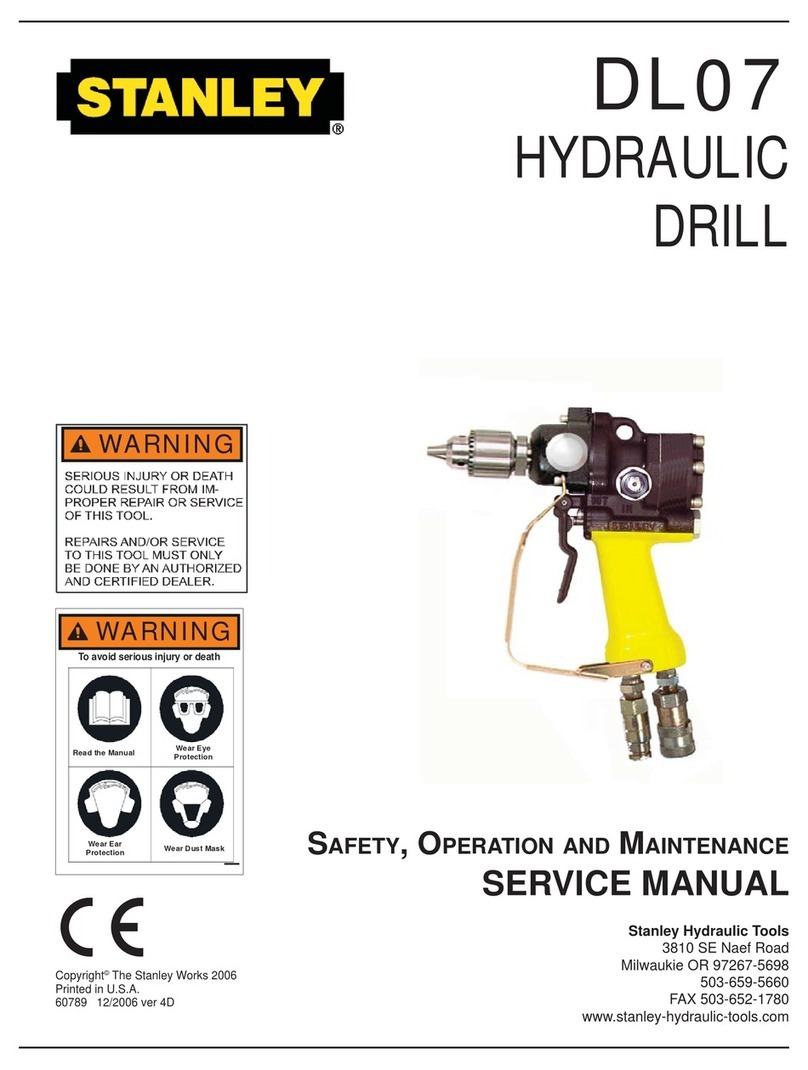
TheSAFETYTAG,P/N15875,shownatright,smaller
thanactualsize,isattachedtothetoolwhenshipped
fromthefactory.Readandunderstandthesafety
instructionslistedonthistagbeforeremoval.We
suggestyouretainthistagandattachittothetool
whennotinuse.
ANameTagStickerisattachedtothetool.Neverexceedtheflowandpressurelevelsspecifiedon
thissticker.Theinformationlistedonthenametagstickermustbelegibleatalltimes.Replacethis
stickerifitbecomeswornordamaged.AreplacementisavailablefromyourlocalStanley
distributor.
ToolDecals&Tags
6
DANGER DANGER
1.FAILURETOUSEHYDRAULICHOSE WHENUSING
HYDRAULICTOOLSONORNEARELECTRICALLINES
MAYRESULTINDEATHORSERIOUSINJURY.
BEFOREUSINGHOSE
ONORNEARELECTRICLINES.
BESURETHEHOSEIS.THE
HOSESHOULDBEREGULARLYTESTEDFORELECTRICCURRENT
LEAKAGEINACCORDANCEWITHYOURSAFETYDEPARTMENT
INSTRUCTIONS.
2.AHYDRAULICLEAKORBURSTMAYCAUSEOIL
INJECTIONINTOTHEBODYORCAUSEOTHERSEVEREPERSONAL
INJURY.
A.DONOTEXCEEDSPECIFIEDFLOWAND
PRESSUREFORTHISTOOL.EXCESSFLOWOR
PRESSUREMAYCAUSEALEAKORBURST.
B.DONOTEXCEEDRATEDWORKINGPRESSURE
OFHYDRAULICHOSEUSEDWITHTHISTOOL.
EXCESSPRESSUREMAYCAUSEALEAKOR
BURST.
C.CHECKTOOL,HOSE,COUPLERS&
CONNECTORSDAILYFOR
LEAKS.DONOTFEELFORLEAKSWITH
YOURHANDS.CONTACTWITHALEAKMAY
RESULTINSEVEREPERSONALINJURY.
LABELEDAND
CERTI-FIEDASNON-CONDUCTIVE
LABELEDANDCERTIFIEDAS
NON-CONDUCTIVE
MAINTAINEDASNON-CONDUCTIVE
D.DONOTLIFTORCARRYTOOLBYTHEHOSES.DONOTABUSE
HOSE.DONOTUSEKINKED,TORNORDAMAGEDHOSES.
3.MAKESUREHYDRAULICHOSESAREPROPERLY
CONN-ECTEDTOTHETOOLBEFOREPRESSURIZING
SYSTEM.SYSTEMPRESSUREHOSEMUSTALWAYS
BECONNECTEDTOTOOL“IN”PORT.SYSTEM
RETURNHOSEMUSTALWAYSBECONNECTEDAT
TOOL“OUT”PORT.REVERSINGCONNECTIONSMAY
CAUSEREVERSETOOLOPERATIONWHICHCAN
CAUSESEVEREPERSONALINJURY.
4.DONOTCONNECTCLOSED-CENTERTOOLSTO
OPEN-CENTERHYDRAULICSYSTEMS.THISMAY
CAUSEEXTREMESYSTEMHEATAND/ORSEVERE
PERSONALINJURY.
DONOTCONNECTOPEN-CENTERTOOLSTOCLOSED-CENTER
HYDRAULICSYSTEMS.THISMAYRESULTINLOSSOFOTHER
HYDRAULICFUNCTIONSPOWEREDBYTHESAMESYSTEMAND/OR
SEVEREPERSONALINJURY.
5.BYSTANDERSMAYBEINJUREDINYOURWORK
AREA.KEEPBYSTANDERSCLEAROFYOURWORK
AREA.
6.WEARHEARING,EYE,FOOT,HANDANDHEADPROTECTION.
7.TOAVOIDPERSONALINJURYOREQUIPMENTDAMAGE,ALLTOOL
REPAIR,MAINTENANCEANDSERVICEMUSTBE
PERFORMEDBYAUTHORIZEDANDPROPERLY
TRAINEDPERSONNEL.
IMPORTANT IMPORTANT
READOPERATIONMANUALAND
SAFETYINSTRUCTIONSFORTHIS
TOOLBEFOREUSINGIT.
USEONLYPARTSANDREPAIR
PROCEDURESAPPROVEDBY
STANLEYANDDESCRIBEDINTHE
OPERATIONMANUAL.
TAGTOBEREMOVEDONLYBYTOOL
OPERATOR.
READOPERATIONMANUALAND
SAFETYINSTRUCTIONSFORTHIS
TOOLBEFOREUSINGIT.
USEONLYPARTSANDREPAIR
PROCEDURESAPPROVEDBY
STANLEYANDDESCRIBEDINTHE
OPERATIONMANUAL.
TAGTOBEREMOVEDONLYBYTOOL
OPERATOR.
(517) (517)15875 15875
SEEOTHERSIDE SEEOTHERSIDE
11207
CircuitType“D”Decal 30Lpmat138bar
BHTMACATEGORY
28323
“CE”Decal
29149
RotationDirectionSticker
60807
DL07ModelSticker
ModelNo.
Dl07
StanleyHydraulicTools
3810SENaefRd
Milwaukie,Oregon97267
15-45lpm/4-12gpm
140bar/2000psi
®
*Notallstickersarefurnishedonalltoolmodels.
Consultpartslistandmodelnumberfordetails.
Correctlyconnecthosestotoolports.Donotexceedspecifiedflowor
pressure.Improperhandling,useormaintenancecancausealeakor
burstthatcanresultinoilinjectiontothebody.Failuretoobservethese
precautionsmayresultinseriouspersonalinjury.
WARNING
58862
PressureWarning
Sticker
28788
ManualSticker
WARNING
ReadownersmanualandensurethatyouPhavebeen
properlytrainedtoworkonorParoundelectriclines.Failureto
usehydraulicPhoselabeledandcertifiedas
non-conductivePmayresultindeathorseriouspersonalinjury.
58864
ElectricalWarningSticker
FORUSEONOPENCENTERANDCLOSED
CENTERHYDRAULICSYSTEMS,"SETFOR
PROPERSYSTEMBEFOREUSE"
OC/CC
11354
OC/CCSticker
8GPM/30LPM
1000RPMAT
RATEDNO-LOADSPEED
29148
RPMSticker
