Star Headlight & Lantern LCS790 Supplement

INSTALLATION AND OPERATING
INSTRUCTION MANUAL
LCS790
LCS790LCS790
LCS790
SIREN AMPLIFIER & LIGHT CONTROLLER
US PATENT D574,799
PLIT411 REV. - 9/23/08

-i-
INSTALLATION INFORMATION
PURCHASE DATE:
INSTALLATION DATE:
INSTALLER:
DEALER:
MODEL:
LCS790
AMPLIFIER SERIAL NO:
CONTROL HEAD SERIAL NO:
ARROWSTICK CONTROL SERIAL NO:
Model and serial number located on bottom of unit
Ins alla ion Informa ion
-ii-
TABLE OF CONTENTS
OVERVIEW 1
PRECAUTIONS 2
CONTENTS 2
SPECIFICATIONS 3
INSTALLATION 4-40
INSTALLER-SELECTABLE OPTIONS 4- 1
DIP Switch Settings 4-9
DIP Switch Chart 6
BUZ (Beep Settings), GUN (Gun Lock), TDM (Traffic Director Mode) 7
PD (Pursuit Disable), AUX (Auxiliary Input), PGM (Programming Mode) 8
PK (Park-Kill Polarity), AUX (Auxiliary Input Polarity) 9
Programmable Settings 9- 1
Detailed Programming Summary Table 10
Detailed Programming Legend 12
Detailed Programming Instructions
(see page 10 for specific page numbers for each option) 12- 1
QUICK INSTALLATION GUIDE CENTERFOLD
MOUNTING 2
ELECTRICAL CONNECTIONS - 9
12-terminal Connector 5
Siren Wiring Diagram #1 6
10-terminal Connector 7- 8
Siren Wiring Diagram #2 9
Label Insertion 40
OPERATION 41-46
ON/OFF 41
SELECTOR SWITCH (ROTARY KNOB) 42
SLIDE SWITCH 4
PUSH BUTTON SWITCHES 4
MANUAL AND HORN BUTTONS 44
Chart of Manual Tones 44
VOLUME CONTROLS 45
MICROPHONE 45
SPEAKER DIAGNOSTICS 45
AUXILIARY INPUT 46
PARK KILL 46
FUSES 46
PARTS 46
SERVICE 47-49
TROUBLESHOOTING 47
WARRANTY 48
RETURN 48
RETURNED GOODS AUTHORIZATION FORM 49
NOTICE
Due to continuous product improvements, we must reserve the right to change any specifications and
information, contained in this manual at any time without notice. Signal Vehicle Products and/or the
manufacturer make no warranty of any kind with regard to this manual, including, but not limited to, the
implied warranties of merchantability and fitness for a particular purpose. Signal Vehicle Products and/or the
manufacturer shall not be liable for errors contained herein or for incidental or consequential damages in
connection with the furnishing, performance, or use of this manual.
Table of Con en s

-1-
LCS790
Overview
The LCS790 Siren Amplifier is a premium 200W unit designed for single or
dual 100W speaker use and full lighting control.
The primary operating modes are Phaser, Yelp, Wail, Hands Free, Manual,
Alert, and Radio. A Noise Canceling PA Override and push-button Horn
Override are available in all modes. A manual push-button is provided for
push-on/push-off tone toggle operation in the Phaser, Yelp, and Wail modes.
It also allows manual siren control in the Manual or PA modes. The Phaser
function can be optionally replaced by Two-Tone or disabled entirely with
programming. Another feature allows cycling through Wail, Yelp, Phaser,
and Standby by providing a signal to the horn ring auxiliary wire when the
function switch is in the Hands Free (HF) position. A Park Kill option is
provided for connection to a door switch, etc. to disable the siren when
exiting the vehicle. Radio and PA volume controls are provided on the front
panel. Also located on the front panel are two LED's for speaker diagnostics.
This unit additionally contains several distinct controls for operation of
vehicle devices. A slide switch allows quick pursuit mode operation. The far
right slide position can be set up to activate maximum lights and siren for
pursuit mode. There are seven push buttons to control up to seven different
lighting or auxiliary functions, or four functions and a traffic director.
The front panel is backlighted with LED's for night visibility. This compact
unit utilizes short circuit, high voltage, low voltage, and reverse polarity
protection systems for maximum service life.
Questio s?
Signal Vehicle Products will attempt to answer and resolve any questions or
issues you may have. Please contact our Customer Service Department at
the number below with any questions. When con ac ing us abou a
produc you have purchased, please have he produc ’s serial number
readily available.
Phone: (585) 226-9025
Fax: (888) 478-2797
www.starheadlight.co
Overview

-2-
Ins alla ion Informa ion
Precautio s
Proper installation of the unit is essential for years of safe, reliable operation.
Please read all instruction before installing the unit. Failure to follow these
instructions can cause serious damage to the unit or vehicle and may void
warranties.
• Installing any siren requires a good understanding of automotive
electronics, systems, and procedures.
• Please read all of the instructions, before attempting to install or
operate any of the sirens.
• Always disconnect power when installing or uninstalling this device.
• Never use a battery charger to bench test this device.
• This product is intended to be installed and operated in interior
applications only.
Keep These Ins ruc ions - Keep these instructions in the vehicle or other
safe place for future reference. Advise the
vehicle operator of the location.
Unpacking - Inspect contents for shipping damage. If found, alert carrier
immediately.
Co te ts
Contents should include:
1 - Siren with Microphone
1 - Mounting Bracket w/Screws
1 - Microphone Bracket w/Screws
2 - Wiring Connectors
1 - Pack of Button Labels
1 - Installation and Operating Instructions
Contact your supplier immediately if any components are missing.

-3-
Specificatio s
Input Voltage
10 - 16 VDC (negative ground)
Input Current
8.0 Amps @ 13.6 VDC (single 100 speaker)
16.0 Amps @ 13.6 VDC (dual 100 speakers)
Standby Current
0 mA while Off, <150 mA with backlighting on
Max Peak Current
50 AMPS (supply circuit must be capable of supplying this for brief period)
Audio Frequency
200Hz - 10 kHz + 3db
Audio Output
40 watts @13.6 VDC
Output Power
105 ATTS RMS MAX. (15.0 VDC – single 100 speaker)
180 ATTS RMS MAX. (15.0 VDC –dual 100 speakers)
Siren Frequency
675Hz - 1633Hz
High Voltage Protection
16 - 18 VDC will cause siren output to cease, resumes at normal voltage
Operating Temperature
-15° F to +140°F
Siren Controls
7-position rotary switch (Radio, Alert, Manual, HF, ail, Yelp, Phaser)
Push-Button Manual and Horn switches
Auxiliary input (DIP switch programmable) for positive or negative horn
-Remote Manual or Hands Free operation
Park Kill input (DIP switch programmable) for positive or negative
activation
Phaser (and Two-Tone) disable (programmable)
Two-Tone activation (swaps modes with Phaser) (programmable)
Diagnostic Indicators
Two LED indicators provide diagnostic feedback for each speaker
Light/Device Controls
7 push-on/push-off buttons
4-position slide switch (Off,
1
11
1
,
2
22
2
, and
3
33
3
)
Light Output Ratings
20A fuse on each of the 10 outputs. (7 push buttons, 3 slide positions)
Siren and Light
Connections
Detachable 12-terminal connector
Detachable 10-terminal connector
1 individual Ground terminal, 3 +12VDC power terminals
Size
6" ide, 8" Deep, 3" High
Shipping eight
6 lbs.
Specifica ions

-4-
I stallatio
Signal Vehicle recommends that you bench test the unit immediately after
receipt to ensure that it was not damaged in shipping. Then you should
program all settings and test again prior to installation.
Optio al Setti gs
The LCS790 has quite a few different options that can be modified to meet
your particular needs. Please review BOTH the list below and the one on
page 10 to determine if you need to change any of the settings for your
application. A more detailed description of each option can be found in the
corresponding sections on pages 7-9 and 12- 1.
If you eed to make a y cha ges to the default setti gs, please do so
prior to i stallatio of the sire .
DIP Swi ch Se ings
Optio Default Setti g Optio al Setti g
Keypad Beep Enabled Silent
Gun Lock Mode Disabled 8-sec. Open
S5, S6, S7 Traffic Director Mode Enabled No Traffic Director
Pursuit Mode for Slide Switch Pos. Enabled No Auto TD & Siren
Aux Wire Control Air Horn Clone Manual Function
Park Kill Wire Polarity Positive Ground/Negative
AUX Wire Polarity Positive Ground/Negative
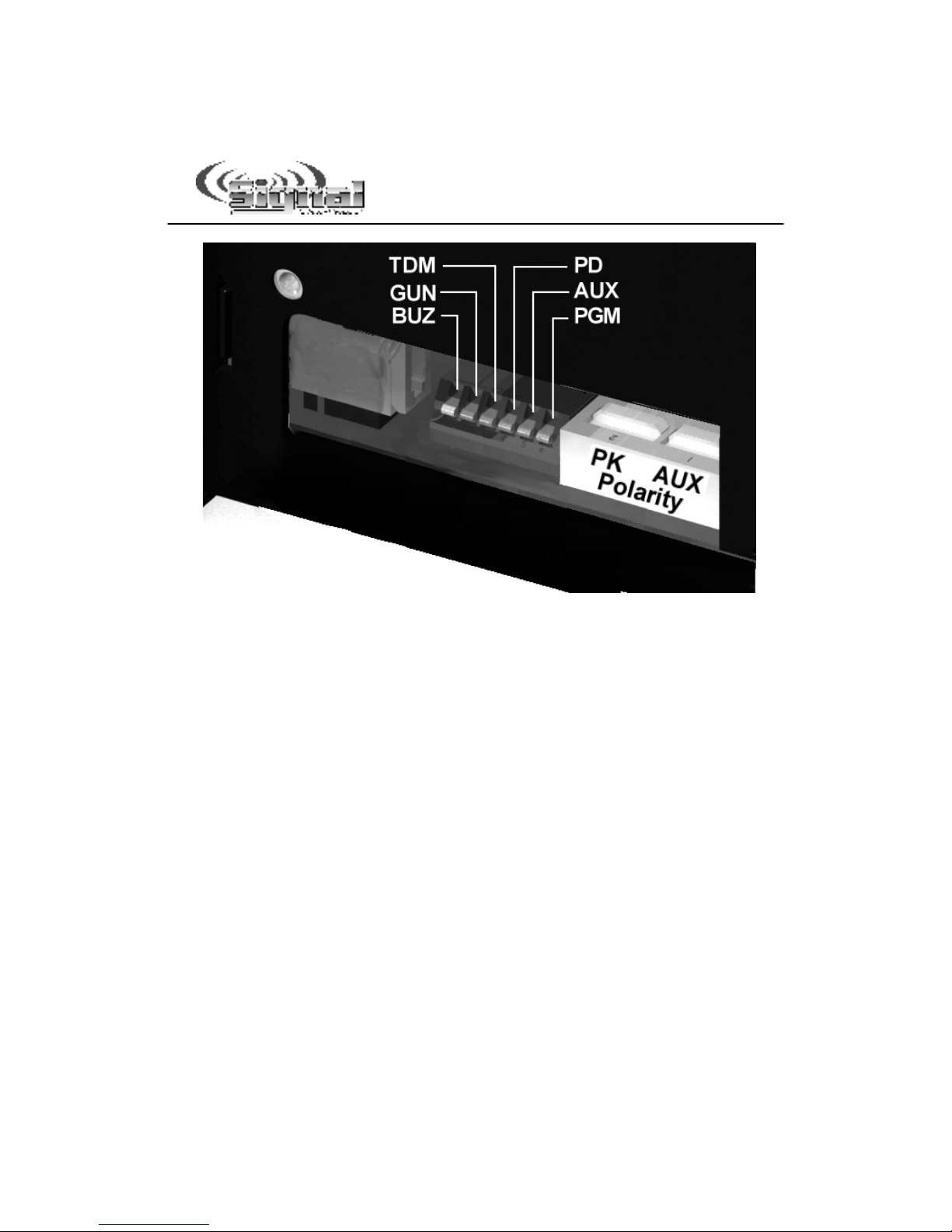
A series of DIP
switches accessible
through the side of the
case, allow the installer
to select these various
options (see the
diagram to the right). If
any changes are
necessary, these
options should be set
before installation of
the unit.
Turn the siren on its
side and find the
location of the DIP
switches
For quick i stallatio usi g all of the default optio s,
please refer to the removable ce terfold guide.
Ins alla ion: Dip Swi ch Se ings
-5-
Ins alla ion: Dip Swi ch Se ings
(co t’d)
UPSIDE DOWN VIEW
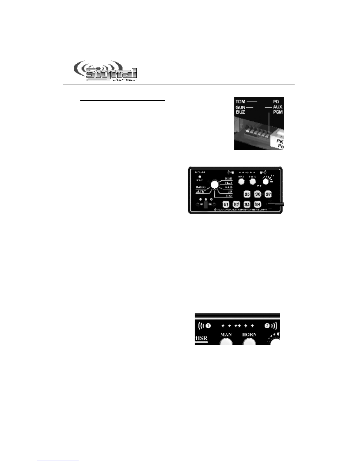
There are two sets of DIP switches located inside the unit. One set has six
switches that move up or down. The default position for all of these switches
is “down” (closer to the circuit board). The other set contains two DIP
switches that slide in or out. The default position for these two switches is
“out” (towards you).
Please review the diagram above to determine which switch controls what
function. A chart summarizing these functions is located on the following
page. Specific detail about each function can be found on pages 7-9.

-6-
Ins alla ion: Dip Swi ch Se ings
(co t’d)
SW
LABEL
FUNCTION
DOWN POSITION
(Default)
UP POSITION
1
BUZ
Beep Setting
Keypad buttons beep
when pressed and
10-second beep option
also available
Keypad buttons silent
when pressed and
No 10-sec beep option
available.
2
GUN
Gun Lock
Switch 4 is a normal On/
Off switch
Switch 4 used to
unlock the Gun Lock
for 8 seconds
TDM
Traffic
Director
Mode
TD Mode Enabled
Buttons 5, 6, and 7 are
used to control a Traffic
Director.
TD LED display on siren
face is activated by
buttons 5, 6, and 7.
Buttons 5, 6, and 7 are
standard On/Off
switches.
TD LED display on
siren WILL NOT
illuminate.
4
PD
Pursuit
Disable
Traffic Director
auto-activated in WARN
mode when slide switch
is in position .
Siren auto-activated in
WAIL mode when slide
switch is in position .
Neither the Traffic
Director nor the siren
is auto-activated when
slide switch is in
position .
5
AUX
AUX Wire
Function
AUX wire used to
activate Air Horn.
AUX wire used to
activate the Manual
function.
6
PGM
Programming
Mode
Siren operates normally.
Places siren into
advanced
programming mode.
SW
LABEL
FUNCTION
IN POSITION
(Default)
OUT POSITION
1
PK
Park-Kill Po-
larity
Park-Kill function is acti-
vated by applying
+12VDC to Terminal 1
of the 10-terminal con-
nector.
Park-Kill function is
activated by applying
grou d to Terminal 1
of the 10-terminal con-
nector.
2
AUX
AUX wire
polarity
AUX function (Air Horn
or Manual) is activated
by applying +12VDC
to Terminal 5 of the
10-terminal connector.
AUX function (Air Horn
or Manual) is activated
by applying grou d
to Terminal 5 of the
10-terminal connector.
UP/DOWN DIP SWITCHES
IN/OUT DIP SWITCHES
-7-
Ins alla ion: Dip Swi ch Se ings
(co t’d)
UP/DOWN DIP Swi ch Se ings
BUZ Beep Settings
By default, every time a button is pressed on the
keypad, the unit beeps. Flip the DIP switch up to
deactivate this feature.
Please ote: The optional 10-second beep
function will not work if this switch is in the UP
position (see page 15 of the Detailed
Programmi g section for further details).
GUN un Lock
This unit is shipped with all of
the Push Buttons (S1-S7) set
to be used as standard
On/Off buttons (pressing
each button once turns it ON,
pressing it a second time
turns it OFF). For some
applications it may be desirable to have one or more “Gun Lock”
buttons. A “Gun Lock” button will stay activated for only 10 seconds
when pressed. To activate Gun Lock Mode, flip switch two up. By
default, the fourth push button (S4) will become a Gun Lock button.
(See page 14 for detailed instructions on how to change the un
Lock button to a different button, to program additional buttons to act
as un Lock buttons, or to change the un Lock Timer to 20 sec.)
TDM Traffic Director Mode
This unit is shipped with buttons S5, S6, and S7 designated for use
with an approved traffic director (arrowstick). If any one of these
buttons is activated, pressing either of the other buttons will
deactivate the active one. In addition, pressing any of these buttons
will also activate the traffic director display LEDs on the front of
the unit. These LEDs will display
the pattern that corresponds to the
buttons pressed (i.e. Warn, Left,
Right, or Center Out). If you do
not have a traffic director, or your
traffic director uses a separate
controller, and you will be using these buttons as standard On/Off
buttons for other functions, flip DIP switch three up. This deactivates
the display LEDs. In addition, it will also allow you to turn them all
on at once (In TDM mode only one at a time can be active).

-8-
Ins alla ion: Dip Swi ch Se ings
(co t’d)
PD Pursuit Disable
The farthest right slide switch
position
is normally used for
“pursuit mode”. By default, when
the slide switch is in position
,
the lights connected to it will
activate, the siren will activate in
Wail mode, and your compatible
traffic director (if connected to this
unit) will activate in the Warn
mode. If you prefer to NOT have the siren and traffic director
automatically activated when the slide switch is moved to position
three, flip DIP switch 4 up. (See pages 20-22 of the Detailed
Programmi g section to program the traffic director and siren
individually).
AUX Auxiliary Input Function
The auxiliary input (terminal 5 of the 10-terminal connector, see
page 38) allows you to either activate the Air Horn, or to "mimic" the
Manual button function, through some other external switch, such
as the vehicle horn switch. The wiring diagram on page 9 shows
two connection examples. NOTE: Perma e t disco ectio of
the vehicle hor is NOT recomme ded. By default, applying
+12VDC to the Auxiliary terminal will activate the Air Horn on the
siren. If you instead prefer to have the AUX wire activate your
Manual function, flip DIP switch 5 up.
PGM Programming Mode
Flipping switch 6 up will place the siren into “Programming Mode”.
This mode will allow you to program additional options. Please see
the Detailed Programmi g section on page 9.
-9-
Ins alla ion: Dip Swi ch Se ings
(co t’d)
De ailed Programming
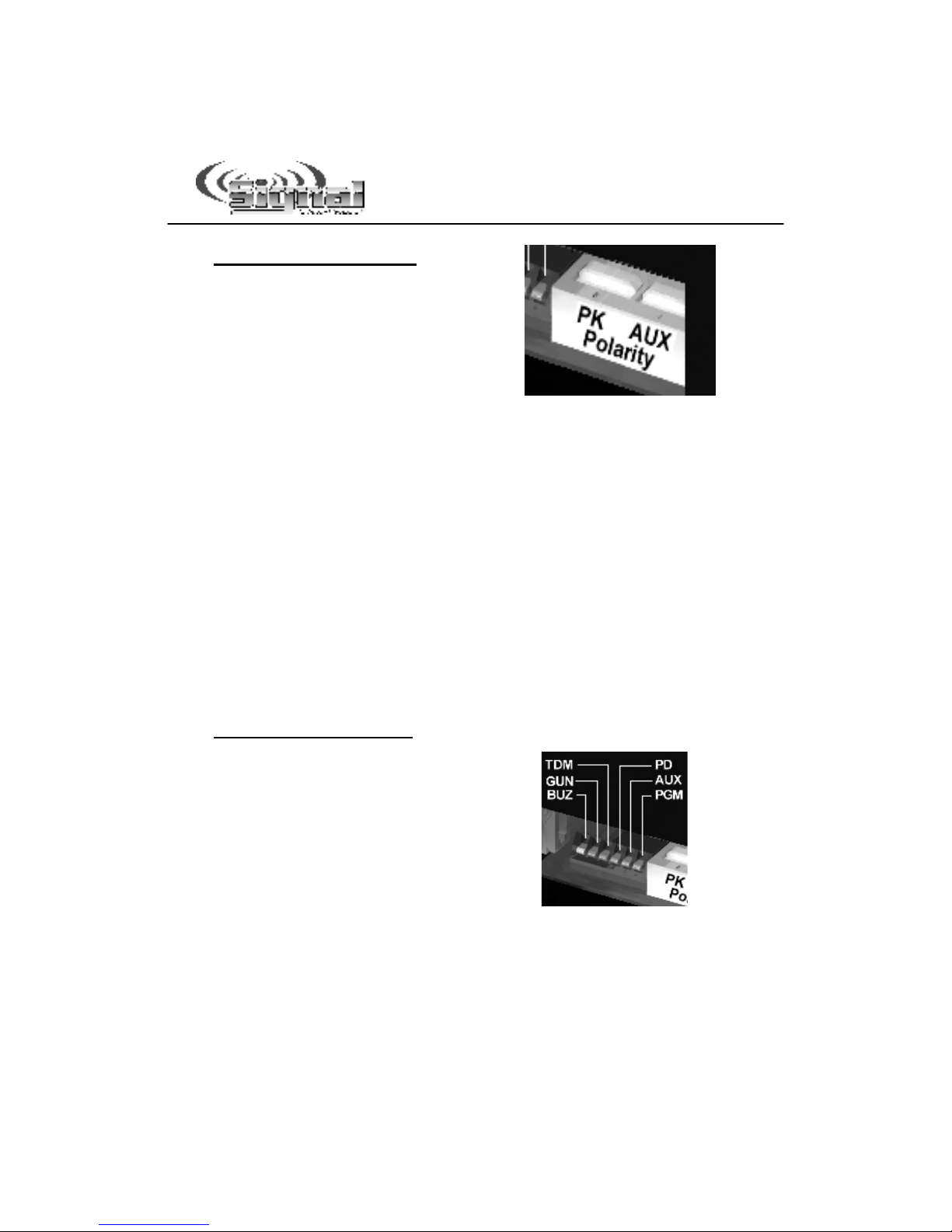
IN/OUT DIP Swi ch Se ings
There are an additional two DIP switches
located to the right of the bank of six.
These switches move in and out, rather
than up and down (like the previous
switches). These two switches are used
to control polarity.
PK Park-Kill Polarity
The Park-Kill input (terminal 1 of the 10-terminal connector, see page
7) will turn off any siren tone output when activated (i.e. vehicle
shifted into park, door opened, etc.). The tones will remain off until a
control on the siren is activated or changed. The wiring diagram on
page 9 shows two connection examples.
The park kill input is normally activated by connecting terminal 1 of
the 10-terminal connector to positive voltage (+12VDC). To activate
by connecting it to ground (negative) instead, push this DIP switch
“in” (switch 2 in the diagram above).
AUX Auxiliary Input Polarity
The auxiliary input (terminal 5 of the 10-terminal connector and
described on the previous page) is normally activated by connecting
terminal 5 to positive voltage (+12VDC). To activate it by connecting
it to ground (negative) instead, push this DIP switch “in” (switch 1 in
the diagram above).
De ailed Programming
DIP switch 6, located on the far right of
the left bank of DIP switches (PGM in the
diagram to the right) is used for
additional programming. Flipping this
switch up will place the siren into
Programming Mode. This mode will
allow you to program several additional
options that you may wish set.
With DIP switch 6 (PGM) in the UP position, use the rotary selector knob
and slide switch to select an option for programming. Then use the
appropriate push button (S1-S7) to select the option. See the chart on the
next page for a summary of the programming options available. Detailed
programming instructions for each option can be found on pages 12- 1.
-10-
Optio Default Setti g Optio al Setti g
Button Operation
(Open or Closed)
Activating a Button (Turning it
on) ill Close The Circuit
(apply +12VDC)
Activating Button (Turning it on) Opens
The Circuit (Off/Not Connected)
Button Operation
(Latched or Momentary) All are Standard On/Off
(Latched) Any Can Be Momentary
Buttons State at Power Up All Are Off at Power Up Any Can Be On
Gun Lock Button Button S4 None, S1, S2, S3, S5, S6, S7
Gun Lock Timer 10 Seconds 20 Seconds
Auto Beep hen Any Function Active Disabled Beeps Every 10 sec.
Steady or Flashing/Pulsed Outputs All Steady Output Any Can Be Pulsed
Pulsed Output Rate Slow Fast
Pulsed Output Phase All Buttons Phase 1 Any Button(s) Phase 2
Manual "Step Up" Function Time Out Never After 15 sec.
Hands Free Tone Sweep Disabled Enabled
Siren Disable (Only PA & Air Horn
Function) Siren Enabled Siren Disabled
Audio Lockout Disabled All Audio Functions Locked Out Until
Button(s) or Slide Switch Programmed
Below are Activated
Audio Lockout Unless Slide Positions 1, 2, and 3 Any Output(s)
Standby Mode (or Stealth Mode) No Standby
All Buttons Enabled Unit in Standby Mode
Until Slide Switch Activated
Slide Switch Progression Progressive 3 Separate Functions
Slide Switch Activates arn Pattern Enabled Disable
Slide Positions for Auto-Activation Slide Position 3 Enable or Disable Any Positions
Basic Slide Switch
Auto-Activation of Siren Tone Enabled Disabled
Advanced Siren Auto-Activation:
ail Tone Slide Switch Position 3 Any Button(s) or Slide Switch
Advanced Siren Auto-Activation:
Yelp Tone Disabled Any Button(s) or Slide Switch
Advanced Siren Auto-Activation:
Phaser Tone Disabled Any Button(s) or Slide Switch
Tone Change Allowed hile
In Audible Pursuit Allowed Not Allowed
Slide Switch Position 1 Auto-Activates
Any Button or Slide Position Disabled Any Button(s) or Slide Switch
Slide Switch Position 2 Auto-Activates
Any Button or Slide Position Disabled Any Button(s) or Slide Switch
Slide Switch Position 3 Auto-Activates
Any Button or Slide Position Disabled Any Button(s) or Slide Switch
Slide Switch Options Auto-Off Enabled Disabled
Rotary Switch Tones Auto-Activate
Slide Switch Functions Rotary Knob
Functions Normally ail, Yelp, Phaser Also
Activate L1, L2, L3
Park-Kill De-activation Of Functions Park-Kill only Disables Siren Park-Kill Disables Both Siren AND any
selected outputs
High-Low Override of Phaser Tone Phaser Tone hen Rotary Knob
in Phaser Position High-Low Tone hen Rotary Knob in
Phaser Position
Phaser Tone Disable Phaser Tone hen Rotary Knob
in Phaser Position Yelp Tone hen Rotary Knob in
Phaser Position
HRT Active Mode HRT ill Always Control Siren HRT ill Only Control Siren If
Programmed Button(s) are ON or
Slide Switch is in Programmed Position(s)
Button(s) or Slide Switch Required For
HRT to Activate LS1, LS2, and LS3 Add Any Button(s) or Remove
Any Slide Switch Positions
Action Terminal Output Steady On (for Video) Pulsed (for Light)
Traffic Director Compatibility TDC850 or DL15-30 2 Alternate Configurations
PG
12
13
13
14
14
15
16
16
16
17
17
18
18
18
19
19
20
20
21
22
22
22
23
23-24
23-24
23-24
24
25
26
27
27
28
28
29
29-30
Detailed Programmi g Summary Table
The optio s below should be programmed PRIOR to i stallatio of your
sire . Refer to pages 12-31 for detailed programmi g i structio s.
Ins alla ion: De ailed Programming
De ailed Programming Summary Table

-11-
Ins alla ion: De ailed Programming
De ailed Programming Legend
Detailed Programmi g Lege d
SLIDE SWITCH
POSITION
ROTARY
KNOB
POSITION
PUSH
BUTTON FUNCTION DEFINITION
HORN
MA
N S7 S6 S5 S4 S3 S2 S1
Default
OFF PHASER ANY
Gun Lock Bu ons
S7 S6 S5 S4 S S2 S1
ONLY S4
OFF YELP ANY
Bu on Opera ion (Open or Closed)
S7 S6 S5 S4 S S2 S1
ALL OPEN
OFF WAIL ANY
Bu on Opera ion (Momen ary or La ched)
S7 S6 S5 S4 S S2 S1 ALL LATCHED
OFF HF ANY
Bu on S a e a Power Up
S7 S6 S5 S4 S S2 S1
ALL OFF
OFF MAN ANY
S eady or Flashing/Pulsed Ou pu s
S7 S6 S5 S4 S S2 S1 ALL STEADY
OFF ALERT S1
Pulsed Ou pu Ra e
SLOW
OFF ALERT S2
Manual "S ep Up" Func ion Times Ou
NEVER
OFF ALERT S
Hands Free Tone Sweep
DISABLED
OFF ALERT S4
Ac ion Terminal Ou pu
STEADY
OFF ALERT S5
Siren Disable (Only PA & Horn Func ions)
SIREN
ENABLED
OFF ALERT S6
Au o Beep When Any Func ion Ac ive
DISABLED
OFF ALERT S7
S andby (S eal h) Mode (
Faceplate Activation w/Slide)
DISABLED
OFF ALERT MAN
Slide Swi ch Au o Ac iva es WARN Pa ern
ENABLED
OFF RADIO S1
High-Low Override of Phaser Tone
DISABLED
OFF RADIO S2
YELP Override of Phaser Tone
DISABLED
OFF RADIO S
Ro ary Swi ch Tones Ac iva e Slide Swi ch
DISABLED
OFF RADIO S4
Basic Slide Swi ch Ac iva ion of Siren
ENABLED
OFF RADIO S5
Slide Swi ch Progression
PROGRESSIVE
OFF RADIO S6
HRT Ac ive Mode (Configure w/
-
RADIO)
ALWAYS
ACTIVE
OFF RADIO S7
Audio Lockou (Config w/
2
22
2
-YELP)
DISABLED
OFF RADIO MAN
NON-Progressive Slide (Toggles Wi h S5)
DISABLED
PHASER ANY
Slide Swi ch 1 Au o-Ac iva es any Ou pu
3
33
3 2
22
2
S7 S6 S5 S4 S S2 S1
NONE
YELP ANY
Park-Kill Deac iva ion of Func ionss
3
33
3
1
11
1&
2
22
2 S7 S6 S5 S4 S S2 S1
NONE
WAIL ANY
Advanced Siren Au o-Ac iva ion: WAIL Tone
3
33
3
1
11
1&
2
22
2 S7 S6 S5 S4 S S2 S1
3
33
3
HF ANY
Advanced Siren Au o-Ac iva ion: YELP Tone
3
33
3
1
11
1&
2
22
2 S7 S6 S5 S4 S S2 S1
NONE
MAN ANY
Advanced Siren Au o-Ac iva ion: PHASER Tone
3
33
3
1
11
1&
2
22
2 S7 S6 S5 S4 S S2 S1
NONE
ALERT S1, S2,
or S
Slide Swi ch Posi ions for Au o-Ac iva ion of
WARN Pa ern
LS LS2 LS1
3
33
3
ONLY
RADIO ANY
Bu on(s) or Slide Swi ch Required for HRT o
Be Ac iva ed
3
33
3
1
11
1&
2
22
2 S7 S6 S5 S4 S S2 S1
, 2
22
2,
OR
3
33
3
2
22
2
PHASER ANY
Slide Swi ch 2 Au o-Ac iva es Ou pu s
3
33
3
1
11
1&
2
22
2 S7 S6 S5 S4 S S2 S1
NONE
2
22
2
YELP ANY
Audio Lockou Unless…
(Only if ENABLED by OFF-RAD-S7)
3
33
3
1
11
1&
2
22
2 S7 S6 S5 S4 S S2 S1
, 2
22
2,
OR
3
33
3
2
22
2
WAIL ANY PB
Pulsed Ou pu Phase (if ac iva ed by OFF-MAN)
S7 S6 S5 S4 S S2 S1
ALL PHASE
1
2
22
2
HF S1
Gun Lock Timer (10 seconds or 20 seconds)
10
SECONDS
2
22
2
HF S2
Slide Swi ch Op ions Au o-Off
ENABLED
2
22
2
HF S
Tone Change Allowed While in Audible Pursui
ALLOWED
2
22
2
HF S4
TD Communica ions Por ON/OFF
ON
2
22
2
HF S5
ALT TD Config 1 - L,R,&W (CO= L&R)
Toggles wi h S6 & 7
OFF
2
22
2
HF S6
Defaul TD Configura ion: DL15-30W-CO,L,&R
(Power On=Warn) Toggles wi h S5 & 7
ON
2
22
2
HF S7
ALT TD Config 2 - L,R, (Power On=CO)
Toggles wi h S5 & 6
OFF
2
22
2
RADIO HORN/
MAN
Rese Siren To Fac ory Defaul s
BOTH
N/A
3
33
3
PHASER ANY
Slide Swi ch 3 Au o-Ac iva es Ou pu s
2
22
2
1
11
1&
2
22
2 S7 S6 S5 S4 S S2 S1
NONE
1 1 1 1 1 1 1 1 1 1 1 1 1 1
Function Controlled By This Button
Button Controls Different Function
Button Does Nothing

-12-
Detailed Programmi g I structio s
Once you have programmed each op ion(s) o he desired se ing
(s), you must flip he PGM DIP swi ch down o save he changes.
Ins alla ion: De ailed Programming
Bu on Opera ion (Open or Closed)
The following section gives a detailed description of how to program each of
the options listed/shown on the previous two pages. If you do no need o
change any of hese op ions, you may skip o he Mou ti g sec ion on
page 32.
Bu on Opera ion (Open or Closed)
All of the Push Buttons (S1-S7), by default, operate as a standard switches
(“normally open”). When the unit is powered up the buttons are in the OFF
mode and the switched circuits are “open”. Pressing each button once will turn
them ON and “close” the connection (apply +12VDC). Pressing each button
again will turn them OFF and open the connection again.
If you would like any of these switches to be “closed” (+12VDC applied) when
they are OFF and “open” when they are ON, change this setting.
Place the PGM DIP switch in this position: Up
Place the Rotary Knob in this position: Yelp
Place the Slide Switch in this position: Off
And toggle any of these buttons: S1-S7
Button is Green: (Default setting for all buttons) When any of the buttons
are activated (or ON), the circuit is “closed” or “connected”
to +12VDC.
Button is Red: The circuit is “open” when ON and “closed” connected to
+12VDC when OFF.
Each button (S1-S7) can be programmed independently of the others.
Once you have programmed your op ion(s) o he desired se ing(s),
you must flip he PGM DIP swi ch down o save he changes.
-13-
Ins alla ion: De ailed Programming
Bu on Opera ion (La ched or Momen ary)
Bu on Opera ion (La ched or Momen ary)
All of the buttons, by default, operate as standard pushbutton switches.
Pressing each button once will turn it ON and pressing it again will turn it
OFF.
If you would like any of these buttons to act as a “momentary” pushbutton
switch instead (ON only while held in), change this setting.
Place the PGM DIP switch in this position: Up
Place the Rotary Knob in this position: Wail
Place the Slide Switch in this position: Off
And toggle any of these buttons: S1-S7
Button is Green: (Default setting) Button operates as a standard
ON/OFF pushbutton switch.
Button is Red: The button will now operate as a momentary switch.
Each button (S1-S7) can be programmed independently of the others.
Once you have programmed your op ion(s) o he desired se ing(s),
you must flip he PGM DIP swi ch down o save he changes.
Push Bu on S a e A Power Up
Each button, by default, operates as a standard switch. When the LCS790
unit is powered up, they are all in the OFF mode. Pressing each button
once will turn it ON and pressing it again will turn it OFF.
If you would like any of these switches to automatically be in the ON
position (activated) when the unit is powered up, change this setting.
Place the PGM DIP switch in this position: Up
Place the Rotary Knob in this position: HF
Place the Slide Switch in this position: Off
And toggle any of these buttons: S1-S7
Button is Green: (Default setting) When the unit is powered up, the
switch is de-activated (or OFF).
Button is Red: When the unit is powered up, the switch is ON.
Please ote: The switches still function normally as an On/Off switch in
either mode. This option only changes whether the switch is automatically
On or automatically Off when the unit is powered up.
Once you have programmed your op ion(s) o he desired se ing(s),
you must flip he PGM DIP swi ch down o save he changes.

-14-
Advanced Gun Lock Programming
Ins alla ion: De ailed Programming
Gun Lock Bu on Op ions
Please Note: You must have the Gu
Lock DIP switch (GUN) o to use these
two features (see page 7).
Op ional Gun Lock Bu on
All of the buttons, by default, operate as
standard push button switches.
Pressing each button once will turn it
ON and pressing it again will turn it OFF.
If you would like any of these buttons to act as a timed
“Gun Lock” pushbutton switch instead (timed ON to
disengage your gun lock), change this setting.
Place the PGM DIP switch in this position: Up
Place the Rotary Knob in this position: Phaser
Place the Slide Switch in this position: Off
And toggle any of these buttons: S1-S7
Button is Green: (Default setting for S1-S3, S5-S7) Button operates as a
standard ON/OFF pushbutton switch.
Button is Red: (Default setting for S4)The button will now operate as a
timed “Gun Lock” switch.
Each button (S1-S7) can be programmed independently of the others.
Once you have programmed your op ion(s) o he desired se ing(s),
you must flip he PGM DIP swi ch down o save he changes.
Gun Lock Timer (10 seconds or 20 seconds)
If you have set one or more of your push buttons to operate as a un Lock button
above, it will default to a 10 second timed switch.
If you would like the timed switch to activate for 20 seconds instead of 10 seconds,
change this setting.
Place the PGM DIP switch in this position: Up
Place the Rotary Knob in this position: HF
Place the Slide Switch in this position:
1
11
1
And toggle this button: S1
S1 is Green: (Default setting) All Gun Lock buttons are activated for
10 seconds.
S1 is Red: All Gun Lock buttons are activated for 20 seconds.
Once you have programmed your op ion(s) o he desired se ing(s),
you must flip he PGM DIP swi ch down o save he changes.

-15-
Ins alla ion: De ailed Programming
Au o Beep Func ion
Please Note: You must have the Beep DIP switch
(BUZ) o to use this feature (see page 7).
Au o Beep When Any Func ion Ac ive
This unit can be programmed to “Beep” every 10 seconds whenever any
functions are activated. This feature is designed to alert the user that
devices which may not be noticed by the user, are still active.
If you would like the unit to beep every 10 seconds when any function is
active, change this setting.
Place the PGM DIP switch in this position: Up
Place the Rotary Knob in this position: Alert
Place the Slide Switch in this position: Off
And toggle this button: S6
If S6 is Green: (Default setting) The unit will NOT auto-beep every 10
seconds.
If S6 is Red: The auto-beep feature is enabled and the unit will bee
every 10 seconds whenever any functions are active.
Once you have programmed your op ion(s) o he desired se ing(s),
you must flip he PGM DIP swi ch down o save he changes.
-16-
Ins alla ion: De ailed Programming
S eady or Pulsed Ou pu Op ions
Pulsed Ou pu Ra e
If you have set any of the outputs to pulse (as described above), they will default
to a slow flashing pattern. If you would like your pulsed outputs to use a fast
flashing pattern, change this setting.
Place the PGM DIP switch in this position: Up
Place the Rotary Knob in this position: ALERT
Place the Slide Switch in this position: Off
And toggle this button: S1
Button is Green: (Default setting) Any pulsed outputs will flash slow.
Button is Red: Any pulsed outputs will flash fast.
Once you have programmed your op ion(s) o he desired se ing(s),
you must flip he PGM DIP swi ch down o save he changes.
Pulsed Ou pu Phase
(for use with two or more pulsed outputs)
If you have set any of the outputs to pulse (as described above), there are two
“phases” each can flash in (Phase 1 alternates with Phase 2). By default, all of
the outputs are set for Phase 1 (they will all flash “On” at the same time). If you
wish any of the outputs to flash in Phase 2 (opposite Phase 1), change this
setting.
Place the PGM DIP switch in this position: Up
Place the Rotary Knob in this position: WAIL
Place the Slide Switch in this position:
2
22
2
And toggle any of these buttons: S1-S7
Button is Green: (Default setting) Output, if pulsed, will flash during Phase 1.
Button is Red: Output, if pulsed, will flash during Phase 2.
Once you have programmed your op ion(s) o he desired se ing(s),
you must flip he PGM DIP swi ch down o save he changes.
———–—Advanced Pulsed Ou pu Programming——–——
S eady or Flashing/Pulsed Ou pu s
The outputs switched by each push button normally apply steady +12 VDC.
If you would like any of these outputs to be flashing or pulsed (i.e. if you were
hooking it up to a light that didn’t have its own flasher), change this setting.
Place the PGM DIP switch in this position: Up
Place the Rotary Knob in this position: MAN
Place the Slide Switch in this position: Off
And toggle any of these buttons: S1-S7
Button is Green: (Default setting) The output will deliver steady +12 VDC.
Button is Red: The output will pulse +12 VDC.
Each button (S1-S7) can be programmed independently of the others. Under
normal operation, the buttons controlling any outputs programmed to flash, will
flash green.
Once you have programmed your op ion(s) o he desired se ing
(s), you must flip he PGM DIP swi ch down o save he changes.

-17-
Ins alla ion: De ailed Programming
MAN S ep Up and HF Sweep Op ions
Manual “S ep-Up” Func ion Time Ou
By default, when a siren tone is
activated, pressing the Manual
button will advance it (or “step it
up”) to the next siren tone, where
it will remain until you deactivate
or change it.
If you would like the Manual button only to temporarily step
up the tone for 15 seconds and then revert back to the
original tone, change this setting.
Place the PGM DIP switch in this position: Up
Place the Rotary Knob in this position: Alert
Place the Slide Switch in this position: Off
And toggle this button: S2
If S2 is Green: (Default setting) Manual button functions normally
(changes tone to next quicker).
If S2 is Red: Manual function will time out after 15 seconds and revert
to the original tone.
Once you have programmed your op ion(s) o he desired se ing(s),
you must flip he PGM DIP swi ch down o save he changes.
Hands Free Tone Sweep
When the rotary selector knob is first placed in HF mode, no sound will be
produced. By default, activating the Auxiliary input (see page 37 of the
Electrical Co ectio s section) will produce the WAIL tone. Activating the
Auxiliary input again will advance it to the next siren tone, where it will
remain until you deactivate or change it. Each time you activate the auxiliary
function it will cycle through the tones:
(WAIL YELP PHASER/TWO-TONE OFF).
If you would like the siren to continually “sweep” through all of these tones at
10 cpm instead of just advancing to the next tone only when the Auxiliary
input is activated, change this setting.
Place the PGM DIP switch in this position: Up
Place the Rotary Knob in this position: Alert
Place the Slide Switch in this position: Off
And toggle this button: S3
If S3 is Green: (Default setting) Auxiliary input functions normally in HF
mode (changes tone to next quicker).
If S3 is Red: Activating the Auxiliary input in HF mode will cause the
siren to “sweep” through all tones. Activating the
Auxiliary input again will deactivate the siren.
Once you have programmed your op ion(s) o he desired se ing(s),
you must flip he PGM DIP swi ch down o save he changes.
Table of contents
Other Star Headlight & Lantern Amplifier manuals


