Star Headlight & Lantern LCS850MG Quick guide

LCS850MG
SIREN AMPLIFIER & LIGHT CONTROLLER
PLIT426 REV. G 7/26/18
INSTALLATION AND INSTRUCTION MANUAL

-i-
Inst ll tion Inform tion
INSTALLATION INFORMATION
MODEL: LCS850MG
AMPLIFIER SERIAL #:
CONTROL HEAD SERIAL #:
PURCHASE DATE:
DEALER:
INSTALLER:
INSTALLATION DATE:
CONTROL HEAD DIP SWITCH OPTIONS
_____ Keypad Beep
_____ Gun Lock
_____ TD Mode
_____ AUX Wire
_____ Audio Pursuit
_____ Visual Pursuit
_____ Progressi e Slide Switch
_____ TD Output
_____ Auto On
_____ Magnum Mode
_____ Radio
_____ Phaser
_____ Sweep
AMPLIFIER DIP SWITCH OPTIONS
_______ AUX Input Polarity
_______ Park-Kill Polarity
TRAFFIC DIRECTOR DIP SWITCH OPTIONS
_____ Phantom Mode
_____ Fast Rate Arrow
_____ Low Power
_____ 6-Head Arrow
_____ Full 8-Head Arrow
_____ Dual Tra elling Arrow
_____ Double Blink End

-ii-
TABLE OF CONTENTS
OVERVIEW 1
PRECAUTIONS 2
CONTENTS 2
SPECIFICATIONS 3
INSTALLATION 4-44
INSTALLER-SELECTABLE OPTIONS 4-34
Control Head DIP Switch Settings 4-8
O er iew Chart 4
BUZZ (Beep Settings), Gun Lock, Traffic Director Mode, AUX (Auxiliary Input) 5
Audio Pursuit, Progressi e Slide Switch, TD Output 6
Auto On, Magnum Mode 7
Radio, Phaser, Sweep, Programming Mode 8
Amplifier Dip Switch Settings 9
Traffic Director Settings 10-13
Standard 8-Output Mode (DIP Switches) 10-12
Traffic Directors With Internal Controllers 13
Programmable Settings 14-34
Detailed Programming Summary Table of Contents 14
Detailed Programming Legend 15
Detailed Programming Instructions
(see page 14 for specific page numbers for each option) 16-34
RESETTING NIT TO DEFA LTS 34
Q ICK INSTALLATION G IDE CENTERFOLD
MOUNTING 35-37
ELECTRICAL CONNECTIONS 38-44
Power and Ground Connections 39
10-terminal Connector (SS and Pushbutton Outputs) 40
Siren Wiring Diagram #1 41
Label Insertion 42
12-terminal Connector (Audio I/O) 43
Siren Wiring Diagram #2 44
LCS850MG-XF12 Microphone Harness 45
OPERATION 46-50
SLIDE SWITCH 46
PUSH BUTTON SWITCHES 46
AUDIO MODE BUTTONS 47
VOLUME CONTROLS 47
MANUAL BUTTONS 48
Chart of Manual Tones 48
AIR HORN 48
Chart of AUX Terminal/HRT Acti ation 49
MAGNUM MODE 49
TRAFFIC DIRECTOR CONTROL BUTTONS 50
SPEAKER DIAGNOSTICS 50
MICROPHONE 50
AUXILIARY INPUT 50
PARK KILL 50
CLONING 51
SERVICE 52-55
FUSES 52
PARTS 52
TROUBLESHOOTING 53
WARRANTY 54
RETURN 54
RETURNED GOODS AUTHORIZATION FORM 55
CONTROL HEAD INSTALLATION TEMPLATE Inside B ck Cover
T ble of Contents

-1-
The LCS850MG Siren Amplifier is a premium 200W unit designed for dual 100W speaker
use and full lighting control. It comes standard with a remote control head and a noise-
cancelling microphone for PA use. The amplifier box contains two separate amplifiers that
allow the user to operate two separate and distinct tones at the same time. This dual tone
(Magnum) feature creates a unique sound that is one of the most attention getting
amplifiers on the market today. The Magnum sound allows a single ehicle to sound like
se eral ehicles tra eling at the same time. Each amplifier can operate one 100W RMS
speaker.
The primary operating modes are Phaser, Yelp, Wail, Hands Free, Manual, and Radio. A
Noise Canceling PA O erride and push-button Horn O erride are a ailable in all modes. A
manual push-button is pro ided for push-on/push-off tone toggle operation in the Phaser,
Yelp, and Wail modes. It also allows manual siren control in the HF and silent modes. The
Phaser function can be optionally replaced by Two-Tone or disabled entirely with
programming. Another feature allows cycling through Wail, Yelp, Phaser, and Standby by
pro iding a signal to the horn ring auxiliary wire when the function switch is in the Hands
Free (HF) position. A Park Kill option is pro ided for connection to a door switch, etc. to
disable the siren when exiting the ehicle. Radio and PA olume controls are pro ided on
the front panel. Also located on the front panel are two LED's for speaker diagnostics.
This unit additionally contains se eral distinct controls for operation of ehicle de ices. A
slide switch allows quick pursuit mode operation. The far right slide position can be set up
to acti ate maximum lights and siren for pursuit mode. There are se en push buttons to
control up to se en different lighting or auxiliary functions, or six functions and a traffic
director.
The front panel is backlighted with LED's for night isibility. This compact unit utilizes short
circuit, high oltage, low oltage, and re erse polarity protection systems for maximum
ser ice life.
Questions?
Signal Vehicle Products will attempt to answer and resol e any questions or issues you
may ha e. Please contact our Customer Ser ice Department at the number below with any
questions. When cont cting us bout product you h ve purch sed, ple se h ve the
product’s seri l number re dily v il ble.
Phone: (585) 226-9025
Fax: (888) 478-2797
www.starheadlight.co
Overview
Overview

-2-
Inst ll tion Inform tion
Proper installation of the unit is essential for years of safe, reliable operation. Please read all
instruction before installing the unit. Failure to follow these instructions can cause serious
damage to the unit or ehicle and may oid warranties.
Installing any siren requires a good understanding of automoti e electronics,
systems, and procedures.
Please read all of the instructions, before attempting to install or operate any of the
sirens.
Always disconnect power when installing or uninstalling this de ice.
Ne er use a battery charger to bench test this de ice.
This product is intended to be installed and operated in interior applications only.
Keep These Instructions - Keep these instructions in the ehicle or other safe place for
future reference. Ad ise the ehicle operator of the location.
Unp cking - Inspect contents for shipping damage. If found, alert carrier
immediately.
Contents should include:
1 - Siren with Microphone
1 - Mounting Bracket w/Screws (Non-Flange version only)
1 - Microphone Bracket w/Screws
3 - Wiring Connectors
1 - Pack of Button Labels
1 - Wire Bundle
1 - Installation and Operating Instructions
Contact your supplier immediately if any components are missing.
NOTICE
Due to continuous product impro ements, we must reser e the right to change any specifications and
information, contained in this manual at any time without notice. Signal Vehicle Products and/or the
manufacturer make no warranty of any kind with regard to this manual, including, but not limited to, the
implied warranties of merchantability and fitness for a particular purpose. Signal Vehicle Products and/or
the manufacturer shall not be liable for errors contained herein or for incidental or consequential damages
in connection with the furnishing, performance, or use of this manual.
Precautions
Contents

-3-
Input Voltage 10 - 16 VDC (negative ground)
Input Current 8.0 Amps @ 13.6 VDC (single 100 speaker)
16.0 Amps @ 13.6 VDC (dual 100 speakers)
Standby Current 0 mA while Off, <150 mA with backlighting on
Max Peak Current 50 AMPS (supply circuit must be capable of supplying this for brief
period)
Audio Frequency 200Hz - 10 kHz + 3db
Audio Output 40 watts @13.6 VDC
Output Power 105 ATTS RMS MAX. (15.0 VDC – single 100 speaker)
180 ATTS RMS MAX. (15.0 VDC –dual 100 speakers)
Siren Frequency 675Hz - 1633Hz
High Voltage Protection 16 - 18 VDC will cause siren output to cease, resumes at normal
voltage
Operating Temperature -15° F to +140°F
Siren Controls 5 pushbutton selectable audio modes-(HF, ail, Yelp, Phaser, Radio)
Push-Button Manual and Horn switches
Auxiliary input (DIP switch programmable) for positive or negative horn
Remote Manual or Hands Free operation
Park Kill input (DIP switch programmable) for positive or negative
activation
Phaser (and Two-Tone) disable (programmable)
Two-Tone activation (swaps modes with Phaser) (programmable)
Diagnostic Indicators Two LED indicators provide diagnostic feedback for each speaker
Light/Device Controls 7 push-on/push-off buttons
4-position slide switch (Off, 1
11
1, 2
22
2, and 3
33
3)
Light Output Ratings 20A fuse on each of the 10 outputs. (7 push buttons, 3 slide positions)
Siren and Light
Connections
Detachable 12-terminal connector
Detachable 10-terminal connector
1 individual Ground terminal, 3 +12VDC power terminals
Size 7-5/8" ide, 9-7/8" Deep, 2-1/8" High
Shipping eight 7 lbs.
Specific tions
Specifications

-4-
Signal Vehicle recommends that you bench test the unit immediately after receipt to ensure
that it was not damaged in shipping. Then you should program all settings and test again
prior to installation.
Optional Settings
The LCS850MG has many different optional settings that can be set with DIP switches or
programmed to meet your particular needs. Please re iew pages 4-34 (Control Head DIP
switches below, Amplifier DIP Switch Settings on page 9, Traffic Director Settings on page 10,
and Detailed Programming on page 14) to determine if you need to change any of the settings
for your application. If you need to make any changes to the default settings, please do
so prior to installation of the siren.
Control He d DIP Switch Settings Overview
(Continue to the next page for detailed descriptions)
Option Default Setting Optional Setting
Keypad Beep (BUZZ) Enabled Silent
Gun Lock Button Enabled Standard On/Off Button
PB13 Traffic Director Mode Enabled No Traffic Director
Aux Wire Control Air Horn Clone Manual Function
Audio Pursuit Enabled/Programmable Disabled
Visual Pursuit Enabled/Programmable Disabled
Progressi e Slide Switch Progressi e Programmable or Non-Progressi e
Traffic Director Output Discrete/8-Output Logic Control (3 or 4 outputs)
Auto On @ Boot No Buttons on @ Boot Programmed Buttons on @ Boot
Magnum Mode @ Boot Enabled Disabled
Radio Button Enabled Disabled/Lighting Control
Phaser Button Enabled Disabled/Lighting Control
Tone Sweep in HF Mode Automatic Manual
Programming Mode Off/Normal Operation On (Set Up Mode)
For quick installation using all of the default options,
please refer to the removable centerfold guide.
Inst ll tion
Control He d Dip Switch Settings Overview
PROG. MODE
DISABLE
SWEEP DISABLE
PHASER ENABLE
RADIO DISABLE
MAGNUM MODE
ON AT BOOT
ON AT BOOT DISABLE
DISCRETE TD
PROGRESSIVE ENABLE
VISUAL PT ENABLE
AUDIO PT ENABLE
AUX
TD MODE
GUN DISABLE
BUZZ
10
19
23485 6 7 11 12 13 14
Installation
(Back of
Control Head)
There are 14 DIP switches located on the
back of the Control Head. The default
position for all of them except for Gun
Lock (DIP switch 2) is “down”.

-5-
Inst ll tion: Dip Switch Settings
Control He d Dip Switch Settings (cont’d)
Buzz, Gun Lock, TD Mode, AUX Input Function
BUZZ (Beep Settings)
By default, e ery time a button is pressed on the keypad, the unit beeps.
Flip the BUZZ DIP switch up to deacti ate this feature.
Please note: There is also an optional 10-second eep setting that can
e set to eep every 10 seconds when ANY function is active. The
optional 10-second eep function will not work if this switch is in the UP
position (see page 18 of the Detailed Programming section for further
details).
Detailed DIP Switch Information
BUZZ
Keyp ad Beep
Silent 1
Gun Lock
Button(s)
No Gun Lock
Button(s)
GUN DISABLE
2
TD MODE
Using
Traffic Director
Not Using
Traffic Director
3
AUX
Acti ates
Air Horn
Acti ates
Manual Function
4
TD Mode (Traffic Director Mode On/Off)
GUN DISABLE
PB14 is defaulted as a 10 second “Gun Lock” button. If you will not
be using the Gun Lock option, flip switch 2 down. PB14 will then
become a standard ON/OFF button.
AUX (Auxiliary Wire Input Function)
Normally the siren Air Horn can be acti ated by using the ehicle
horn switch (or other external switch) to apply +12VDC to the
auxiliary input (terminal 7 of the 12-terminal connector, see pages
43-44).
If you instead prefer to ha e the AUX wire acti ate your Manual
function, flip DIP switch 4 up.
NOTE: If the AUX wire DIP switch is set for the MANUAL function
(and the HRT is connected), neither your vehicle horn, nor
the siren Air Horn will sound when you press your steering
wheel horn during a siren tone.
PB13 is normally used to control an appro ed traffic director
(arrowstick) by scrolling through the four main traffic directing patterns:
WARN, LEFT, RIGHT, and CENTER OUT. Flip DIP switch 3 up to
disable the traffic director mode and to use PB13 for ON/OFF control
of the PB13 output (see wiring diagram on page 41), .

-6-
Inst ll tion: Dip Switch Settings
Control He d Dip Switch Settings (cont’d)
Audio Pursuit, Visu l Pursuit, Progressive SS, nd TD Comp tibility
AUDIO PURSUIT ENABLE (DIP switch 5) and VISUAL PURSUIT ENABLE (DIP switch 6)
Normally slide switch position
acti ates “Pursuit Mode”:
a. The lights connected to all 3 slide switch positions will acti ate.
b. The siren will acti ate in Wail mode.
c. Your compatible traffic director (if connected to this unit) will acti ate in the
Warn mode.
To disable automatic acti ation of the siren (A DIO P RS IT) in position
, flip DIP
switch 5 up.
To disable automatic acti ation of the traffic director (VIS AL P RS IT) in position
,
flip DIP switch 6 up.
VISUAL PT ENABLE
AUDIO PT ENABLE
TD Auto-Acti ates in
Pursuit or Programmable
Traffic Director Does NOT
Auto-Acti ate in Pursuit
Siren Auto-Acti ates in
Pursuit or Programmable
Siren Does NOT
Auto-Acti ate in Pursuit
56
PROGRESSIVE ENABLE
Progressi e SS
Non-Progressi e SS
or Programmable SS
DISCRETE TD
Use 3 or 4 Output Signal for
TD w/Internal Controller
(Logic Controlled)
Use Built-In 8-Output
Siren TD Controller
8
PROGRESSIVE ENABLE (Progressive Slide Switch Ena le)
Normally the slide switch is “progressive”, meaning that each
position will add another function while keeping the pre ious
one(s) on. Position
1
11
1
acti ates the first function. Position
2
22
2
acti ates the functions connected to both
1
11
1
and
2
22
2
. Position
will acti ate all of the functions connected to
1
11
1
,
2
22
2
, and
3
33
3
.
To disable this feature so that each slide switch position is
independent from the others, flip DIP switch 7 up.
DISCRETE TD (Traffic Director Compati ility: 8-Output or 4-Output Logic)
TD Mode DIP switch (switch #3) must e ON (see page 5)!!
The default settings of this unit allow for operation
of our standard 8-head traffic directors (i.e. TD77,
TD92, TD93) through an internal controller within the
LCS850MG using 10 outputs from the 12-terminal
connector.
If the traffic director you will be using has a built-in
controller and only needs three or four “signal” wires to
operate, then flip DIP switch 8 up.
With this switch up, the default setting will be for
operation of our DL15-30W. To program the LCS850MG
to operate other traffic directors, please refer to page 32
of the Detailed Programming section.

-7-
ON AT BOOT DISABLE (Push Button State At Power Up)
If you would like any of the push button switches to automatically
be “ON” when the unit is powered up, flip DIP switch 2 up. By
default, if you flip switch 9 up, PB5 will be ON at boot up.
Please see page 17 of the Detailed Programming section for further
instructions on selecting which buttons you would like “ON” at power
up.
Please note:The switches still function normally as an On/Off
switch in either mode. This option only allows you to
select whether the switch is automatically On or
automatically Off when the unit is powered up.
MAGNUM MODE ON AT BOOT (On At Power Up)
(For details on Magnum Mode see page 48)
Normally, the siren is in Magnum mode at boot up. If you
would like it to be in standard mode (non-Magnum/single tone),
flip the 10th switch from the left (switch 10) up.
Please Note: This option only affects which mode the siren is
in at oot. Magnum Mode can still e switched to
at any time.
Inst ll tion: Dip Switch Settings
Control He d Dip Switch Settings (cont’d)
Button Auto On, M gnum Mode, nd R dio Rebro dc st
MAGNUM MODE
ON AT BOOT
Siren in Magnum
Mode at Boot
Siren in Single Tone
Mode at Boot
10
PROG. MODE
DISABLE
SWEEP DISABLE
PHASER ENABLE
RADIO DISABLE
MAGNUM MODE
ON AT BOOT
ON AT BOOT DISABLE
DISCRETE TD
PROGRESSIVE ENABLE
VISUAL PT ENABLE
AUDIO PT ENABLE
AUX
TD MODE
GUN DISABLE
BUZZ
101 92 3 4 85 6 7 11 12 13 14
RADIO DISABLE (Radio Re roadcast or ON/OFF Switch for Output 7)
Normally, the RADIO button is used to
rebroadcast the two-way radio o er the
PA system of the siren. If you will not
be using this feature, you can instead
use the RADIO button to control the
PB13 output (see the wiring diagram on
page 41).
To use the RADIO button to control the PB13 output, flip
DIP switch 11 up.
NOTE : To use the RADIO utton to control the PB13 output, the TD MODE
DIP switch (#3) MUST also e in the DOWN position.
RADIO DISABLE
RADIO Button Rebroadcasts
Radio O er PA
11
RADIO Button
Controls PB13 Output

-8-
Inst ll tion: Dip Switch Settings
Control He d Dip Switch Settings
(cont’d)
Ph ser, Sweep, Progr mming Mode
PHASER ENABLE (Optional Phaser Tone or ON/OFF Switch for the PB13 output)
Normally, the PHASER button is used to acti ate
the Phaser siren tone. If you will not be using this
feature/tone, you can use the PHASER button to
control the PB13 output (see the wiring diagram
on page 41) y flipping DIP switch 12 UP.
NOTE : The PHASER Button cannot e used to
control the PB13 output if either DIP switch
#3 (TD MODE) or DIP switch #11 (RADIO)
is UP (those options override this one).
PHASER ENABLE
12
PHASER Button
Acti ates Phaser Tone
PHASER Button Controls
The PB13 Output
Auto Tone
Sweep in HF
Manual Tone
Cycle in HF
SWEEP DISABLE
13
PROG. MODE
DISABLE
Standard Operation
Siren In
Programming Mode
14
SWEEP DISABLE (‘Manually Cycle’ or ‘Auto-Sweep’ Siren Tones in HF Mode)
When the siren is placed in Hands Free Mode (by pressing
the HF button), no sound will be initially produced.
Normally, acti ating the Auxiliary Input/HRT (see page 43 of
the Electrical Connections section) or mo ing the slide
switch to position
3
33
3
, will acti ate the siren with a “WAIL”
tone. Then you can manually cycle through all of the tones
using the AUX input/HRT.
(WAIL YELP PHASER/TWO-TONE OFF).
If you instead would like the siren to automatically “sweep” through all of
the tones when acti ated, flip DIP switch 13 up.
(Optionally if you’d like the sweep option descri ed here to only function in
HF with the AUX input, and NOT in Slide Switch
3
33
3
, then see the Tone
Sweep Disable section on page 28).
PROG. MODE DISABLE (Programming Mode)
To access the additional “programmable” options described in the
Detailed Programming section on pages 14-34, flip this switch up.
After programming the siren, return the switch to the Standard
Operation location.
NOTE : The siren WILL NOT operate while in Programming Mode.
DIP switch 14 must e in the “down” position for proper
operation of the siren.

-9-
Inst ll tion
Amplifier DIP Switch Settings
AUX Input Pol rity nd P rk-Kill Pol rity
Auxiliary Input Polarity
The auxiliary input (see AUX WIRE on page 5 and see Termin l 7 of the 12-terminal
connector on page 43) is normally acti ated by connecting terminal 7 to positi e oltage
(+12VDC). (See Positive Switching A X and PK Switching diagram a ove).
To acti ate the AUX function by connecting the corresponding terminal to ground
(negati e) instead, turn switch 2 (AUX POS SWITCHING) “OFF” and turn switch 4 (AUX
NEG SWITCHING) “ON” (see Negative Switching A X and PK Switching diagram
a ove).
Park-Kill Polarity
The Park-Kill input (Termin l 3 of the 12-terminal connector, see page 43) is used to
automatically turn off any siren tone output when acti ated (i.e. ehicle shifted into park,
door opened, etc.). The tones will remain off until a control on the siren is acti ated. The
wiring diagram on page 44 shows two connection examples.
The park kill input is normally acti ated by connecting it to positi e oltage (+12VDC).
(See Positive Switching A X and PK Switching diagram a ove).
To acti ate the Park-Kill feature by connecting it to ground (negati e) instead, turn switch
1 (PK POS SWITCHING) “OFF” and turn switch 3 (PK NEG SWITCHING) “ON” (see
Negative Switching A X and PK Switching diagram a ove)
!!! CAUTION !!!
BOTH AUX SWITCHES MUST BE SET
CORRECTLY or this feature will not work.
Amplifier DIP Switch Settings
There are four additional DIP switches located on the amp box near the connectors (see
diagram elow). These four switches are used to control the polarity of your Auxiliary function
and your Park-Kill function.
There are TWO switches that must be set for Auxiliary Polarity and TWO switches that must
be set for Park-Kill Polarity. You must set BOTH switches correctly for each function.
1 2 3 4
OFF
PK POS SWITCHING
AUX NEG SWITCHING
PK NEG SWITCHING
AUX POS SWITCHING
ON
(DOWN)
Positive AUX
nd PK Switching
1 2 34
OFF
ON
(DOWN)
PK POS SWITCHING
AUX NEG SWITCHING
PK NEG SWITCHING
AUX POS SWITCHING
Neg tive AUX
nd PK Switching
!!! CAUTION !!!
BOTH PK SWITCHES MUST BE SET
CORRECTLY or this feature will not work.
(DEFAULT)

-10-
Inst ll tion
Tr ffic Director Settings
This section only applies to those applications in which the TD CYCLE on the control
head will be used to operate a traffic director (arrowstick). If you are NOT using this
button to control a traffic director, you can skip to page 14, after ensuring that DIP switch 3
(TD MODE), on the back of the Control Head, is in the OFF position (see page 5).
Tr ffic Director Settings
PB13 is normally used as a TD Cycle
button to control an appro ed traffic
director (arrowstick) by scrolling through
the four main traffic directing patterns:
WARN, LEFT, RIGHT, and CENTER OUT.
Pressing this button will acti ate your
traffic director and will illuminate the TD
Indic tor LEDs on the bottom of the
control head in the same pattern that the
traffic director is displaying.
By default, the LCS850MG is compatible with any of our ground-side switched 8-head traffic
director (e.g. TD77, TD92, TD93, etc.) and will use its own internal controller to dri e the
“dummy” heads in the traffic director. The Standard 8-Output Mode is also compatible with 6-
head traffic directors (e.g. lightbars with only 6 TD heads) or 8-head TDs in which only 6
heads are used in the traffic directing pattern (and the heads on each end are flashed back
and forth).
If your traffic director has a built-in TD controller and only requires “Signal” or “Logic” inputs
(e.g. the DL15-30W), there are also three (3) additional TD compatibility modes. Skip to page
13 if you will be using a controller that is already built in to your traffic director.
Standard 8-Output Mode (default setting)
If you will be using the internal
controller of the LCS850MG to
operate your traffic director,
please erify that DIP switches
3 and 8 on the back of the
control head are set properly.
(See pages 5 & 6)
Connect the 10 wires from your traffic director harness to the 12
-terminal connector that plugs into
the back of the LCS850MG-AMP
box. The last two terminals of
the connector will be empty.
If you are only
controlling six
heads, do not use
terminals 1 and 8.
8-Output Discrete Wiring
Traffic Director Harness
7 (Violet)
C ble Shield (Ground)
RED WIRE (MAX 20 AMPS)
8 (Gr y)
4 (Yellow)
6 (BLUE)
3 ( Or nge)
5 (GREEN)
2 (Red)
1 (Brown)
This section only applies to those Traffic Directors that normally require a
separate control box and use inputs for each indi idual head. Skip to page 13 if
you will be using a controller that is already built in to your traffic director.
DISCRETE TD
Use 3 or 4 Output Signal for
TD w/Internal Controller
(Logic Controlled)
Use Built-In 8-Output
Siren TD Controller
8
TD MODE
Using
Traffic Director
Not Using
Traffic Director
3

-11-
Phantom Mode
TRAFFIC DIRECTING HEADS
THESE TWO HEADS ALTERNATE
Inst ll tion
Tr ffic Director Settings: St nd rd 8-He d Tr ffic Directors (cont’d)
BANK 2BANK 1
DOUBLE BLINK END
(Future Use)
DUAL TRAVELLING ARROW
1 2 34
ON
OFF
6-HEAD ARROW
4
LOW POWER
3
FAST RATE ARROW
21
PHANTOM MODE DISABLE
FULL 8-HEAD ARROW
Internal TD DIP Switches
There are se eral additional programmable options for
standard 8-head (or 6-head) traffic directors that
utilize the internal controller. Re iew these options
below and determine if you will need to change any of
the default settings.
TD DIP Switch Access
1. Loosen the two Phillips head screws that secure
the access co er to the top of the siren.
2. Locate the DIP switches inside the housing
towards the right hand side.
3. There are two banks of four
switches. .
4. Replace the co er when finished.
Fast Rate Arrow (switch 3/ ank 1)
This option will “speed up” the flash rate of the arrowstick. Typically this is used for high
speed or high traffic areas where iewing time of the arrow is limited. To set your
arrowstick to display a “Fast Arrow”, mo e DIP switch 3 of the first bank of DIP switches
TOWARDS the edge of the siren (DOWN).
Phantom Mode (switch 4/ ank 1)
Phantom Mode is designed to
use 6 of the 8 heads for traffic
directing.
In the Phantom mode, the end
lights are NOT part of the
“traffic directing” patterns.
Both of the end lights will flash
back and forth in a high speed
“warn” type display any time the
slide switch is in position 2
22
2.
The end lights of your traffic director automatically
flash in a “random flicker” pattern with the slide
switch in position 3 (see TRAFFIC DIRECTOR
VIS AL P RS IT on page 31).
Normally the LCS850MG will use all 8 heads as part
of the traffic directing pattern. To switch to Phantom
mode, mo e DIP switch 4 (on the far left of the first
bank of DIP switches) AWAY the edge of the siren
(UP).

-12-
Inst ll tion
Tr ffic Director Settings: St nd rd 8-He d Tr ffic Directors (cont’d)
Dual Traveling Arrow (switch 3/ ank 2)
Normally, when the traffic director is in one of its “arrow” modes (Right or Left), the arrow
will start on one side and illuminate the lights, adding one at a time. Optionally, you may
choose a Dual Tra elling Pattern, where energy sa ing is desired. In this case only two
heads will illuminate at any gi en time, and “tra el” across the arrowstick in the direction
you select. (NOTE: The Dual Travelling Pattern option is NOT availa le if the controller
set for Phantom or Dou le Blink Mode.) If you wish to use the Dual Tra elling Pattern
instead of the Standard Pattern, then mo e this DIP switch TOWARDS the edge of the
siren.
Double Blink L st He d (switch 2/ ank 2)
The last head to flash in an arrow can be optionally selected to blink twice at the end of
the arrow sequence. (NOTE: The Dou le Blink Last Head option is NOT availa le if the
controller set for Phantom Mode.) If you wish to Double Blink the last head, mo e this DIP
switch TOWARDS the edge of the siren (DOWN).
OFF
Standard Left Arrow Pattern Dual Travelling Left ArrowPattern
Low Power (switch 2/ ank 1)
If the arrow stick is to be used for nighttime operation, or you wish to reduce the power
consumption of the arrow stick, the output can be reduced by 50%. To set your
arrowstick to run under Low Power, mo e this DIP switch TOWARDS the edge of the
siren.
Six Head Arrow (switch 1/ ank 1)
This option should be used if your traffic director contains only six heads. In this mode,
under all patterns the 1
st
& 8
th
heads will alternate back & forth, operating as rear flashers.
This differs from Phantom Mode, which flashes the end heads only when the Slide
Switch is in position 2
22
2 or 3
33
3. (NOTE: This option is NOT a ailable if the controller set for
Phantom Mode.) If you wish to operate your traffic director in 6-Head mode, then mo e
this DIP switch TOWARDS the edge of the siren.
Full 8-Head Arrow (switch 4/ ank 2)
Many arrow sticks contain
directional arrows (actual
“points”) on either end (the 1
st
and 8
th
heads). Because of
this, the default setting is for a 7-head pattern that will automatically skip the first head in
the right or left patterns so as to not confuse the dri er with the incorrect arrow direction. If
your arrow stick does not contain directional arrows on the ends and you wish to use all
eight heads in your right and left patterns, then mo e this DIP switch TOWARDS the edge
of the siren. (This option is not availa le if the controller is set for Phantom Mode.)
END HEADS w/ARROWS

-13-
Traffic Directors with Built In Controllers
(Logic Controlled)
The LCS850MG has three different “logic controlled” modes that can be used, depending
upon the input requirements of your Traffic Director. These are as follows:
DL15-30W Configuration: Stick operated with 4 wires (Warn/Power, Left, Right, and C/O)
Left Arrow acti ated by power to Warn+Left wires from stick
Right Arrow acti ated by power to Warn+Right wires from stick
C/O acti ated by power to Warn+C/O wires from stick
WARN pattern acti ated by Warn/Power wire
Alt. TD Configuration #1: Stick operated with 3 wires (Warn, Left, and Right)
Warn, Left, and Right each operate independently
C/O acti ated by power to only Left+Right wires from stick
Alt. TD Configuration #2: Stick operated with 3 wires (Center-Out, Left, and Right)
C/O, Left, and Right each operate independently
No Warn Pattern
Inst ll tion
Tr ffic Director Settings: Tr ffic Directors with Built-In Controllers
This section only applies to those Traffic Directors that ha e a built-in controller,
but will be operated with the TD CYCLE button through “signal” wires.
TD MODE
Using
Traffic Director
3
Not Using
Traffic Director
TD OUTPUT
Use Built-In 8-Output
Siren TD Controller
Use 3 or 4 Output Signal for
TD w/Internal Controller
(Logic Controlled)
8
POWER/CENTER-OUT
LEFT
RIGHT
WARN
LEFT
RIGHT
POWER/WARN (Red)
RIGHT (Green)
CENTER-OUT (Purple)
LEFT (Yellow)
CENTER-OUT= LEFT+RIGHT
LEFT=
RIGHT=
CENTER-OUT=
LEFT+POWER/WARN
RIGHT+POWER/WARN
CENTER-OUT+POWER/WARN
LEFT=
RIGHT=
-
LEFT+POWER/CENTER-OUT
RIGHT+POWER/CENTER-OUT
NO WARN
DEFA LT
FOR EITHER OF THESE LOGIC
O TP TS, YO M ST CHANGE
THE TD SETTINGS!!
(SEE PAGE 32)
! !
GROUND-Option l (Black)
3-WIRE LOGIC + POWER
(DL15-30W) 2-WIRE LOGIC + POWER
(Alt. TD Configuration #2)
3-WIRE INDEPENDENT LOGIC
(Alt. TD Configuration #1)
If you will be using the TD CYCLE button on the
LCS850MG control head to operate your “logic
controlled” traffic director i.e. its own internal
controller), please erify that DIP switches 3 and 8 on
the back of the control head are set properly. (See
pages 5 & 7)
Re iew the appropriate diagram
abo e and connect the necessary
wires from your traffic director
harness to the corresponding
terminals on the 12-terminal
connector that plugs into the back
of the LCS850MG-AMP box.
See page 32 to program
the siren for each of the
appropriate
configurations described
above.

-14-
Detailed Programming Summary Table
The options below should be programmed PRIOR to installation of your siren.
Refer to pages 15-34 for detailed programming instructions.
Inst ll tion: Det iled Progr mming
Det iled Progr mming Summ ry T ble
Option Default Setting Optional Setting PG
Button Operation
(Open or Closed)
Activating a Button (Turning it on) ill
Apply +12VDC (Closed)
Activating Button (Turning it on) Opens
The Circuit (Off/Not Connected) 17
Push Button State at Power Up PB5 On (if enabled by DIP switch 9) Any Can Be On at Power Up
Button Operation
(Latched or Momentary) All are Standard On/Off (Latched) Any Can Be Momentary
18
Auto Beep hen Any Function
Active Disabled Beeps Every 10 sec.
ARN Pattern Excluded From TD
Pattern Cycle Button ARN Pattern Included No ARN Pattern in TD Cycle
Gun Lock Timer Button Assignment Button PB14 None, PB1, PB2, PB3, PB4, PB5, PB13 19
Gun Lock Timer Period 10 Seconds 20 Seconds
Gun Lock Pass Code Enable No Passcode Needed Passcode Need to Unlock Gun 20
Setting the Gun Lock Pass Code PB1, PB3, PB5 Any Buttons (PB1-PB5) 21
Radio/PA Speaker Diagnostic POP Radio and PA send POP signal No POP
Steady or Flashing/Pulsed Outputs All Steady Output Any Can Be Pulsed
22
Pulsed Output Rate Slow Fast
Pulsed Output Phase All Buttons Phase 1 Any Button(s) Phase 2
Manual "Step Up" Function Time Out Never Times Out Times Out After 15 sec.
23
Manual ind Down Function MAN Tone inds Down hen MAN
Button Released
MAN Tone Stops Immediately hen
MAN Button Released
Siren Disable—Only PA & Air Horn
Function Siren Enabled Siren Disabled
24
Audio Lockout Disabled All Audio Functions Locked Out Until
Button(s) or Slide Switch Programmed
Audio Lockout Unless Select If Enabled, Slide Positions 1, 2, and 3 Any Output(s)
Audio Pursuit Options AIL in Slide Position 3 Any Tone In Any SS Position or Any PB 25
Audio Pursuit Mode (HF or AIL) AIL mode activated in pursuit HF mode activated in pursuit
26 HF Mode at Boot No Mode Active at Power Up Siren In HF Mode at Power Up
Quick Shot Tone Replaces Air Horn Air Horn Quick Shot Tone hen Air Horn Pressed
Second Tone Swap in Magnum
Mode
2nd Tone of Magnum Mode Stepped
Up in SS3
2nd Tone of Magnum Mode Staggered
Clone of First Tone in SS3 27
Tones Sweep Disable in HF for Slide
Switch Position 3
Tones Sweep in HF Mode and SS3 if Sweep
Feature Enabled by DIP
Tones Do Not Sweep in HF Mode and
SS 3 28
High-Low Override of Phaser Tone Phaser Tone hen PHSR Button
Pressed
High-Low Tone hen PHSR Button
Pressed
Horn Ring Transfer Active Mode Always Active - Vehicle Horn (HRT)
ill Always Control Siren
Vehicle Horn (HRT) ill Only Control
Siren If Programmed Button(s) are ON
or Slide Switch is in Programmed
Position(s) 29
Button(s) or Slide Switch Required For
HRT to Activate If Enabled, SS1, SS2, and SS3 Add Any Button(s) or Remove Any Slide
Switch Positions
Slide Switch Programming (if
enabled) None Any Button or SS output Can Be
Activated By Any SS Position 30
Slide Switch Options Auto-Off Enabled Disabled 31
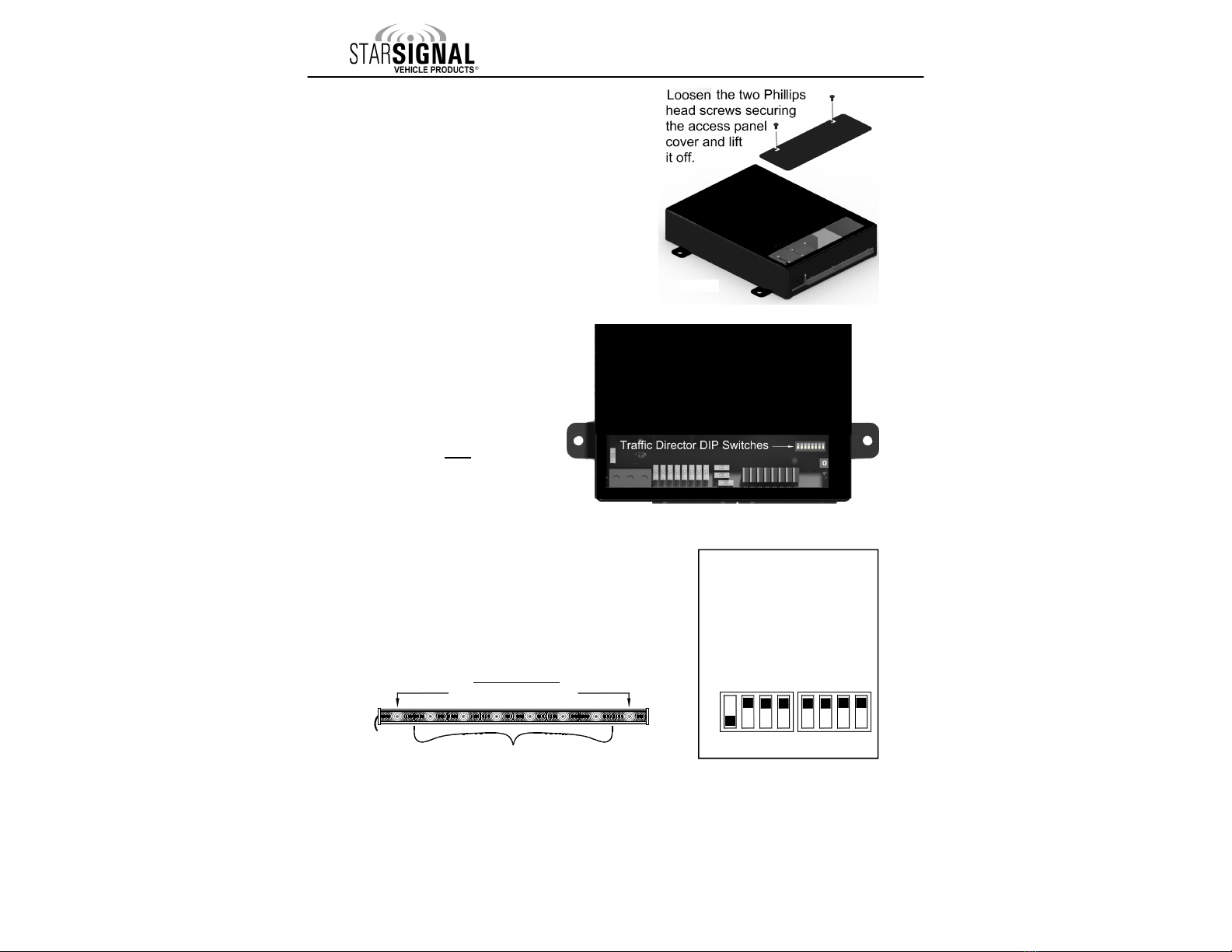
Traffic Director Visual Pursuit Option TD ARN Auto-Activates in SS3 Enable or Disable Any Positions
Logic Controlled TD Output Select 3- ire LOGIC + Power 3- ire Independent or 2- ire+Power 32
TD Logic Polarity Positive Switching Negative Switching
Function hen Ground Applied to
Optional Input 1 Dim Backlighting Gun Lock
33
Function hen +12VDC Applied to
Optional Input 2 Gun Lock Dim Backlighting
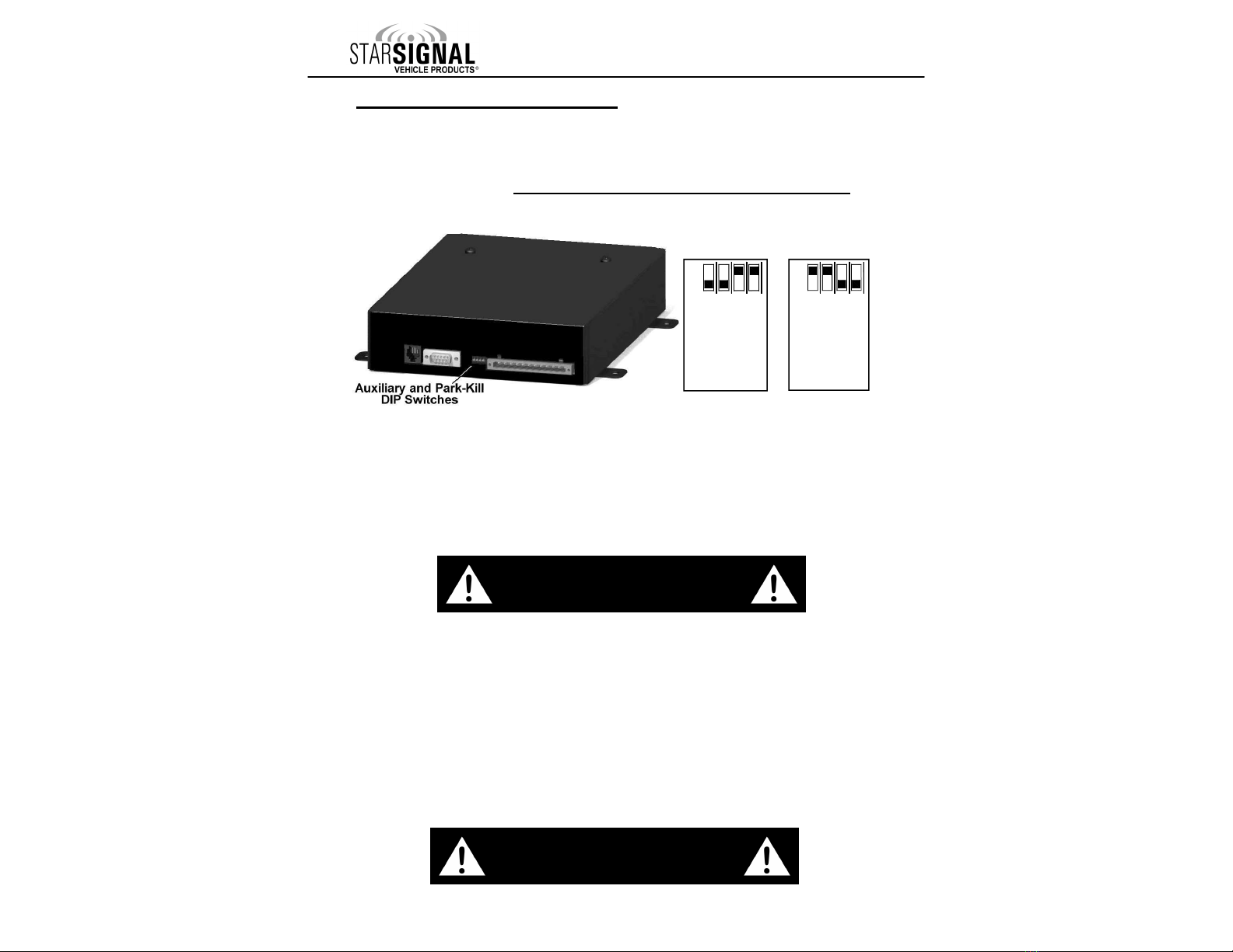
Park-Kill De-activation Of Lights Park-Kill only Disables Siren Park-Kill Disables Both Siren AND any
selected outputs 34
Reset To Defaults Disabled Reset Siren to Factory Default Settings

-15-
Inst ll tion: Det iled Progr mming
Det iled Progr mming Legend
SLIDE
SWITCH
POSITIO
N
A DIO
MODE
B TTON
P SH
B TTON
DEFA LT
SETTING F NCTION DEFINITION
MAN
HORN
PB1
PB2
PB3
PB4
PB5
PB13
PB14
OFF HF ALL PB ONLY PB4
Gun Lock Buttons
PB1 PB2 PB3 PB4 PB5 PB13 PB14
OFF WAIL ALL PB ALL OPEN
Button Oper tion (Open or Closed)
PB1 PB2 PB3 PB4 PB5 PB13 PB14
OFF YELP ALL PB ALL STEADY
Ste dy or Fl shing/Pulsed Outputs
PB1 PB2 PB3 PB4 PB5 PB13 PB14
OFF PHASER ALL PB
ALL LATCHED
Button Oper tion (Moment ry or L tched)
PB1 PB2 PB3 PB4 PB5 PB13 PB14
OFF RADIO ALL PB ALL OFF
Button St te t Power Up
PB1 PB2 PB3 PB4 PB5 PB13 PB14
OFF OFF PB1 SLOW
Pulsed Output R te
PB1
OFF OFF PB2 DISABLED
M nu l "Step Up" Function 15-Sec. Time Out
PB2
OFF OFF PB3 ENABLED
R dio nd PA Test “POP”
PB2
OFF OFF PB4 SIREN
ENABLED
Siren Dis ble (Only PA & Horn Functions)
PB4
OFF OFF PB5 DISABLED
Auto Beep When Any Function Active
PB5
OFF OFF PB13 ENABLED
Second Tone Sw p in M gnum Mode & SS
3
33
3
PB13
OFF OFF PB14 ENABLED
Tone Sweep Dis ble in HF for SS
3
33
3
PB14
HF ANY PB
OR SS NONE
Slide Switch
Auto-Activ tes ny Output
2
22
2 3
33
3
PB1 PB2 PB3 PB4 PB5 PB13 PB14
WAIL ANY PB
OR SS NONE
P rk-Kill De ctiv tion of Functions 1
11
1&2
22
2
3
33
3
PB1 PB2 PB3 PB4 PB5 PB13 PB14
YELP ANY PB ALL
PHASE 1
Pulsed Output Ph se (if ctiv ted by OFF-YELP)
PB1 PB2 PB3 PB4 PB5 PB13 PB14
PHASER PB1-PB5 1, 3, 5
Set P ss Code For Gun Lock Rele se
PB1 PB2 PB3 PB4 PB5
OFF MAN WARN
INCLUDED
Remove W rn P ttern From TD Cycling
MAN
OFF PB1 10 SEC.
Gun Lock Timer (10 seconds or 20 seconds)
PB1
OFF PB2 ENABLED
Slide Switch Options Auto-Off
PB2
OFF PB3 AIR HORN
Quick Shot Tone Repl ces Air Horn
PB3
OFF PB4 POSITIVE
Positive or Neg tive Switched LOGIC Arrowstick
PB4
OFF PB5 OFF
ALT TD Config 1 - L,R,&W (CO= L&R) Toggles
with PB13 & PB14
PB5
OFF PB13 ON
Def ult TD Configur tion: DL15-30W-CO,L,&R
(Power On=W rn) Toggles with PB5 & PB14
PB13
OFF PB14 OFF
ALT TD Config 2 - L,R, (Power On=CO) Toggles
with PB5 & PB13
PB14
2
22
2
HF ANY PB
OR SS NONE
Slide Switch
2
22
2
Auto-Activ tes Outputs
1
11
1 3
33
3
PB1 PB2 PB3 PB4 PB5 PB13 PB14
2
22
2
WAIL ANY PB
OR SS NONE
Button(s) or SS Required for HRT Activ tion 1
11
1&2
22
2
3
33
3
PB1 PB2 PB3 PB4 PB5 PB13 PB14
2
22
2
YELP ANY PB
OR SS NONE
Audio Lockout Unless… (Only if ENABLED by
OFF-RAD-PB14) 1
11
1&2
22
2
3
33
3
PB1 PB2 PB3 PB4 PB5 PB13 PB14
2
22
2
PHASER PB1-PB3 SS
3
33
3
ONLY
SS Positions for Auto-Activ tion of WARN P tt.
1
11
1
2
22
2
3
33
3
2
22
2
RADIO HORN/
MAN N/A
Reset Siren To F ctory Def ults
BOTH BOTH
2
22
2
OFF PB1 DISABLED
High-Low Override of Ph ser Tone
PB1
2
22
2
OFF PB2 DISABLED
Wind Down MAN Tone In HF Mode
PB2
2
22
2
OFF PB3 ALWAYS ON
HRT Active Mode (Configure w/SS
2
22
2
-WAIL)
PB3
2
22
2
OFF PB4 DISABLED
Audio Lockout (Config w/SS
2
22
2
-YELP)
PB4
2
22
2
OFF PB5 DISABLED
Gun Lock Rele se P ss Code Required
PB5
2
22
2
OFF PB13 DISABLED
HF Audio Mode t Boot
PB13
2
22
2
OFF PB14 WAIL
Audio Pursuit = WAIL or HF
PB14
3
33
3
HF ANY PB
OR SS NONE
Slide Switch
3
33
3
Auto-Activ tes Outputs
1
11
1 2
22
2
PB1 PB2 PB3 PB4 PB5 PB13 PB14
3
33
3
WAIL ANY PB
OR SS SS
3
33
3
Auto-Activ tion of Siren in WAIL Tone 1
11
1&2
22
2
3
33
3
PB1 PB2 PB3 PB4 PB5 PB13 PB14
3
33
3
YELP ANY PB
OR SS NONE
Auto-Activ tion of Siren in YELP Tone 1
11
1&2
22
2
3
33
3
PB1 PB2 PB3 PB4 PB5 PB13 PB14
3
33
3
PHASER ANY PB
OR SS NONE
Auto-Activ tion of Siren in PHASER Tone 1
11
1&2
22
2
3
33
3
PB1 PB2 PB3 PB4 PB5 PB13 PB14
3
33
3
OFF PB5 ENABLED
Ground Option l Input 2 to Dim B cklighting
PB5
3
33
3
OFF PB13 DISABLED
+12VDC to Option l Input 1 to Dim B cklighting
PB13
3
33
3
OFF PB14 DISABLED
Ground Option l Input 2 to En ble Gun Lock
PB14
3
33
3
OFF MAN ENABLED
+12VDC to Option l Input 1 to En ble Gun Lock
MAN
.
For quick reference later, we recommend highlighting any
of the optional settings you ha e programmed.
Button Controls This Function
Button Controls Different Function
Button Does Nothing

-16-
Detailed Programming Instructions
Inst ll tion: Det iled Progr mming
Pl cing the Siren Into Progr mming Mode
The following section gi es a detailed description of how to program each of the options listed
on the pre ious two pages. If you do not need to ch nge ny of these options, you m y
skip to the Mounting section on p ge 35.
PROG. MODE (Programming Mode)
To access the additional “programmable”
options described in this Detailed
Programming section on pages 17-34, you
must place the unit into “Programming Mode”:
Locate the DIP switches on the back of the
Control Head.
Once you h ve progr mmed ll necess ry options, you must flip
the Progr mming Mode DIP switch down to s ve the ch nges.
Once you h ve progr mmed ll necess ry options, you must flip
the Progr mming Mode DIP switch down to s ve the ch nges.
PROG. MODE
DISABLE
Standard Operation
Siren In
Programming Mode
14
PROG. MODE
DISABLE
Standard O peration
Siren In
Programming Mode
14
PROG. MODE
DISABLE
SWEEP DISABLE
PHASER ENABLE
RADIO DISABLE
MAGNUM MODE
ON AT BOOT
ON AT BOOT DISABLE
DISCRETE TD
PROGRESSIVE ENABLE
VISUAL PT ENABLE
AUDIO PT ENABLE
AUX
TD MODE
GUN DISABLE
BUZZ
101 92 3 4 85 6 7 11 12 13 14
Flip DIP switch 14 up, placing the unit into Programming Mode.
Program any of the options listed in this section that you need.
After programming the siren, return the switch to the Standard Operation
location to “SAVE” the programming.
NOTE : The siren WILL NOT operate while in Programming Mode.
DIP switch 14 must e in the “down” position for proper
operation of the siren.

-17-
Inst ll tion: Det iled Progr mming
Button Oper tion (Open or Closed)
Button St te t Power Up
All of the Push Buttons (PB1-PB5, PB13,
PB14), by default, operate as standard
switches (“normally open”). Pressing each
button once will turn them ON and “close” the
connection (applies +12VDC to the
corresponding output). Pressing each button
again will turn them OFF and open the
connection again.
If you would like any of these switches to be
normally “closed” (outputting +12VDC) when
they are OFF (Green) and “open” when they are ON (Red), change this setting.
Button is Green: (Default setting for all uttons) When any of these buttons are acti ated
(or ON), the circuit is “closed” or “connected” to +12VDC.
Button is Red: The circuit is “open” (or OFF) when ON and “closed” (or ON/connected to
+12VDC) when OFF.
Each button (PB1-PB5, PB13, PB14) can be programmed independently of the others.
Button Oper tion (Open or Closed)
Once you h ve progr mmed ll necess ry options, you must flip
the Progr mming Mode DIP switch down to s ve the ch nges.
Once you h ve progr mmed ll necess ry options, you must flip
the Progr mming Mode DIP switch down to s ve the ch nges.
Push Button St te At Power Up
Please Note: You must have control head DIP switch 9 (On at Boot Disable) up (Off) to use
this feature (see page 7).
If you would like any of the pushbutton switches to automatically be in the ON position
(acti ated) when the unit is powered up, change this setting:
Button is Green: (Default setting for all ut PB5) When the unit is powered up, these buttons
will be OFF.
Button is Red: (Default setting for ONLY PB5) When the unit is powered up, these buttons
will be ON.
Please note: The switches still function normally as an On/Off switch in either mode.
This option only changes whether the switch is automatically On or
automatically Off when the unit is powered up.
Programming Mode DIP switch: p
Slide Switch: Off
Acti ate this button (RED): WAIL
Modify any of these buttons: PB1-PB5, PB13, PB14
Programming Mode DIP switch: p
Slide Switch: Off
Acti ate this button (RED): RADIO
And modify any of these buttons: PB1-PB5, PB13, PB14
All of the options on pages 17
All of the options on pages 17All of the options on pages 17
All of the options on pages 17-
--
-34 can optionally be programmed using free software and a
34 can optionally be programmed using free software and a 34 can optionally be programmed using free software and a
34 can optionally be programmed using free software and a
USB to serial cable ( /N SUSB
USB to serial cable ( /N SUSBUSB to serial cable ( /N SUSB
USB to serial cable ( /N SUSB-
--
-850MG) available upon request from StarSignal at 585
850MG) available upon request from StarSignal at 585850MG) available upon request from StarSignal at 585
850MG) available upon request from StarSignal at 585-
--
-226
226226
226-
--
-9787.
9787.9787.
9787.
Other manuals for LCS850MG
1
Table of contents
Other Star Headlight & Lantern Amplifier manuals