STAR TEC CAPTURE RADAR PRO 2.2.2 User manual

1
CAPTURE RADAR PRO 2.2.2
Microwave motion detector for industrial doors* (2 m - 10 m)
Technical data may be changed without prior warning.
* The use of the sensor other than described cannot be guaranteed by the manufacturer.
** Under optimal ambient conditions.
1
346
5
2
1. Front cover
2. OLED display
3. Programming Buttons and LEDs
4. Radar module
5. Dip switch
6. Mounting bracket
1TECHNICAL SPECIFICATIONS
Technology: Microwave doppler radar
Transmission frequency: 24,150 GHz
Transmitter radiated power: < 20 dBm EIRP
Transmitter power density: < 5 mW/cm2
Detection mode: Motion
Detection zone: 34° x 80°
Minimum detection speed: 5 cm/s**
Supply voltage: 12V/24V AC/DC insert a 1A fuse on external power supply
Mains frequency: 50 - 60 Hz
Max power consumption: < 2 W
Outputs: 2 outputs: NO/NC configuration (Normally open/closed)
Max. load voltage: 42V peak or DC; Max. load current: 500 mA
Mounting height: 2-10 m
Protection class: IP65
Temperature range: -30 °C to +60 °C
Inclination angles: 0° to 45° vertically; +30°, +15°, 0°, -15°, -30° horizontally
Materials: ADA + Polycarbonate
Weight: 240g without cable, 637g with cable
Cable lenght: Available in 4 versions: a) 6 m, b) 8 m, c) 10 m, d) 15 m
Norm conformity:
EN IEC 62311:2020; EN IEC 62368-1:2014/AC:2015/AC:2017/A11:2017;
EN 55032:2015 + A11:2020; EN 55035:2017/A11:2020;
ETSI EN 301 489-1 V2.2.3; ETSI EN 301 489-3 V2.1.1;
ETSI EN 301 489-17 V3.2.4; EN 300 328 V2.2.2
Art. 50500400 Art. 50500441
Art. 50500442 Art. 50500443
2
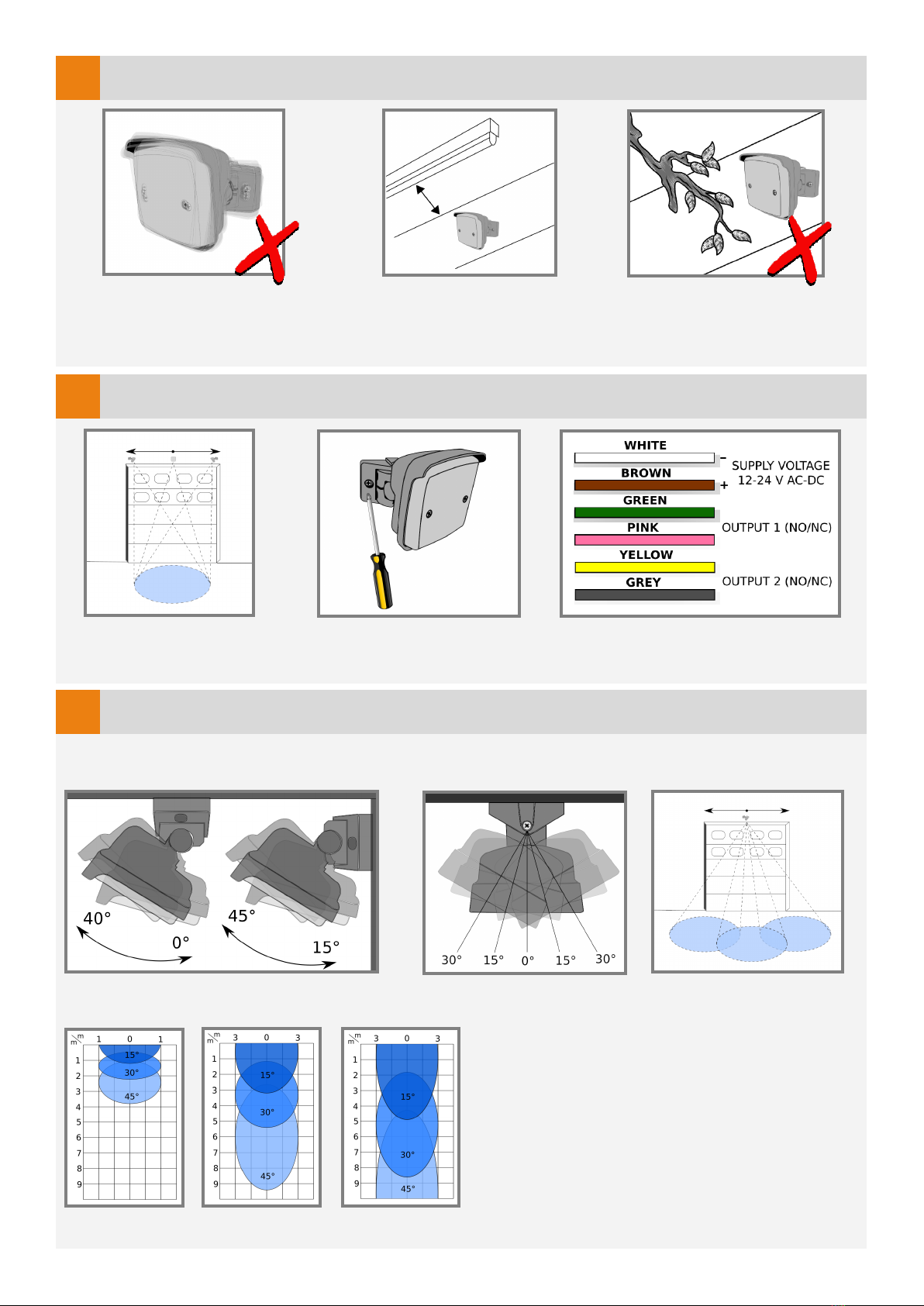
2MOUNTING ADVICE
Mount sensor away
from fluorescent or
HID light sources.
Adjust horizontal angle:
Mounting height:
Can be mounted on the
entire lenght of the
door.
2 m 5 m 8 m With the double joint, the angles can be adjusted
quickly and easily as required.
4
Avoid unstable surfaces
and vibrations.
3
Objects such as fans,
plants, etc must not
protrude into the detection
area.
MOUNTING AND WIRING
Adjust the vertical angle depending on wall
or ceiling mounting.
Connect the wires to the door
controller/inverter.
Tilt completely the sensor on
one side to have access to
fixing holes.
DETECTION FIELD ADJUSTMENTS
The dimensions of the detection field were measured under optimal conditions with the standard value for
field size (4)

3
5
Remove the 2 front cover fixing screws to access the programming buttons and
the OLED display.
CONFIGURATION THROUGH OLED DISPLAY
When idle, the message “CAPTURE OLED” appears on the display.
Press one of the 2 buttons to enter the configuration menu. You will hear a confirmation tone.
Press the right button to go to the next parameter.
Press the left button to go to the previous parameter.
To select a parameter, press both buttons at the same time. You will hear a confirmation tone.
Press the right button to increase the value.
Press the left button to decrease the value.
Press both buttons at the same time to confirm the value displayed. You will hear a confirmation tone.
Keep pressed the right button for 3 seconds to exit the parameter configuration menu without modifying
the value. You will hear a confirmation tone.
Select to exit the configuration menu (You will hear a confirmation tone), or wait 30 seconds to exit
automatically.
To RESTORE THE FACTORY SETTINGS, press both buttons until the LEDs flash.
Before restoring factory settings you must exit the configuration menu.
The configuration is done via 2 buttons with which you can select the
parameters on the OLED display.
1) FIELD SIZE
15° 20° 25° 30° 35° 40° 45°
2) SENSITIVITY
1234567
3) HOLD-OPEN TIME
1s 2s 3s 4s 5s 6s 7s
4) VIBRATIONS SUPPRESSION
1234567
6) CROSS-TRAFFIC FILTER
O 132
7) OUTPUT 1 CONFIGURATION
(NC)(NO)
8) DETECTION TYPE 1
12) DETECTION MODE 2
11) DETECTION TYPE 2
9) DETECTION MODE 1
10) OUTPUT 2 CONFIGURATION
(NC)(NO)
14) EXIT
PARAMETERS EXPLAINED IN DETAIL IN PARAGRAPH 6.
(page 4)
CALENDAR SCHEDULER
YYYY-MM-DD
HH:MM:SS
5) MOUNTING HEIGHT
2-2,4m 2,5-2,9m 3-3,9m 4-4,9m 5-5,9m 6-6,9m 7-7,9m 8-8,9m 9-9,9m

4
2. Radar sensitivity: Regulate the sensibility and anti-interference filter. Starts from level 1 (maximum sensibi-
lity + minimum anti-interference filter), to level 7 (minimum sensibility + maximum anti-interference filter);
3. Hold-open time: Sets the time during which the door stays open. Starts from level 1 (1 second), to level 7 (7
seconds); Longer times are configurable only with the app;
4. Vibrations suppression: in case of strong vibrations, you can use this filter to avoid
disturbances. Selection from level 1 (no filters) to level 7 (strong filters). We recommend leaving the default
value set;
5. Mounting height: Sets the installation height of the device. Fundamental for the correct
function of the sensor;
O Door opens at every movement
1Door occasionally opens when crossing trac is detected
2Door rarely opens when crossing trac is detected
3Door never opens by cross trac
6PARAMETERS CONFIGURATION
1. Field dimension: Regulate the width of the detection area. Starts from
level 1 (minimum width), to level 7 (maximum width). More specific confi-
guration can be set with the smartphone app;
6. CrossTraffic Filtering: Allows to ignore traffic that moves parallel to the door;
1234567
-15°,+15° -20°,+20° -25°,+25° -30°,+30° -35°,+35° -40°,+40° -45°,+45°
For optimal operation, indicate in the App where the radar is installed (central/ right cor-
ner/ left corner). By default, it is set to "central".
9. Outputs detection mode: Sets the detection direction of approaching objects (1) ,
receding objects (2) , both directions (3).
7. Outputs configuration: NO output (normally open), NC output (normally closed);
8. Outputs detection type: Vehicles (1), people (2), people and vehicles (3);
123456789
2 - 2,4 m 2,5-2,9 m 3 - 3,9 m 4 - 4,9 m 5 - 5,9 m 6 - 6,9 m 7 - 7,9 m 8 - 8,9 m 9 - 9,9 m
People cannot be detected beyond height of 7,5 m.
5
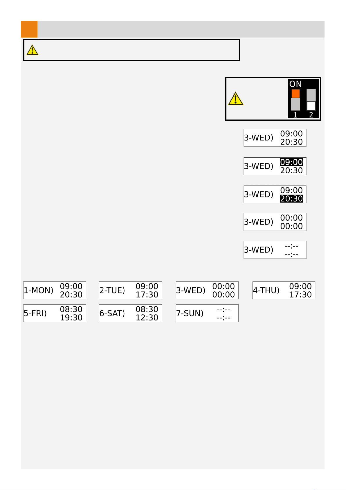
7CALENDAR SCHEDULER
The calendar function allows you to programm the operating times of the radar. To activate this function, you need
an initial configuration via the free app App Capture. After launching the
app on your smartphone, connect to the radar to automatically synchronise
the time and date.
CONFIGURATION VIA OLED DISPLAY
Enter menu 13 CALENDAR SCHEDULER by pressing both buttons
(you will hear a confirmation tone).
Select the day tou want to configured and press both buttons to start the
configuration (confirmation tone). Fig. 1
Select the radar starting time using the right button to increase by 30 minutes at
a time (from 00:00 to 23:59), and the left button to decrease it. Fig. 2
Press both buttons to confirm the start time (confirmation tone).
Now select the ending time in the same way as previously explained. Fig. 3
To exit the configuration menu, keep the right button pressed, or just wait 30
seconds to automatically exit.
24h/24h operation
Simply set the same start and end time. Fig. 4
Radar disabled
The radar can be disabled for the whole day. After you have entered the
configuration of the day, press and hold the left button. You will hear a
confirmation tone and dashes will appear instead of the time. Fig. 5
Configuration example
DIP SWITCH 1
must be set
ON.
Fig. 1
Fig. 2
Fig. 3
Fig. 4
Fig. 5
To use this feature, plug in the baery before the installaon.

6
8DIP SWITCH AND OTA UPDATE
Normally DIPs must be set Off.
DIP 1: when set On, enables battery use.
DIP 2: when set On, enables OTA (Over the air) update with the following procedure:
• Disconnect power supply and set DIP 2 ON;
• Connect power supply and wait until the 3 LEDs flash continuously;
• Set DIP 2 to Off and create a hotspot with your smartphone. Enter SSID: "Capture" and PASSWORD:
"password";
• The radar connects to the hotspot and the LEDs stop flashing. During the download, only the green LED flashes.
• At the end of the download the LEDs will flash 2 times.
Only set DIP 1 ON during the installation in order to not drain the batte-
ry.
The OTA update can also be started from the smartphone app.
9LED MEANING
LD8 - Watchdog. Firmware (flashes at steady frequency).
LD6, LD7, LD8 - Flash when switching on and during a
Bluetooth pairing.
LD0 - Power supply OK
LD1 - Output CH1 enabled
LD2 - Output CH2 enabled
Radar sensor detections
L3 - Direction (ON = approaching, OFF = receading)
L4 - Angulation (OFF = left side, ON = right side)
L5 - Micro-detection
7
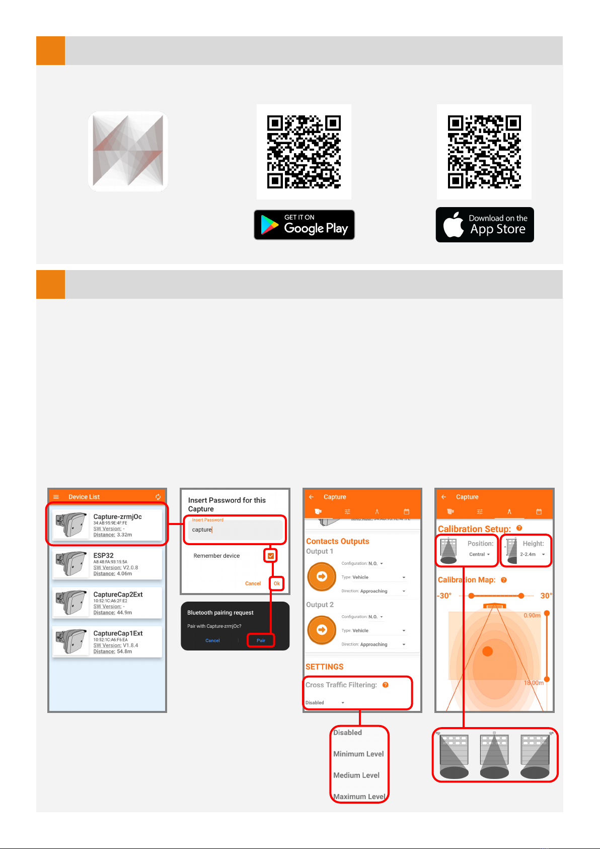
10 SMARTPHONE APPLICATION
The radar can also be configured through the free CaptureRadar app, available for Android and iOS.
The only way to access the change of advanced parameters is to request the password from the dealer.
Quick installation configuration:
1) After opening the app, select your device from the list. Fig 1
2) Enter the default password "capture" and press ok. (For security reasons, we recommend that you change it later).
Your smartphone will ask you to pair your Bluetooth device. Agree. Fig 2
3) Activate the Cross Traffic Filter before entering the calibration setup. Fig 3
4) Enter the "calibration setting" menu and select the position (left, centre, right from the door) and the mounting
height. The Radar will then use the AutoTune function to automatically set the appropriate parameters. Fig 4
5) The configuration is finished. Optional: In the "calibration setting" page (Fig 4) it is possible to plot the radar
detection in real time. And it is possible to adjust the ground projection by changing the angles and the minimum
and maximum detection distances.
11 APP INITIAL SETUP
Fig 1
Fig 2
Fig 3 Fig 4
Search “Capture Radar Startec” on
your App Store, or use the QR_Code.
8
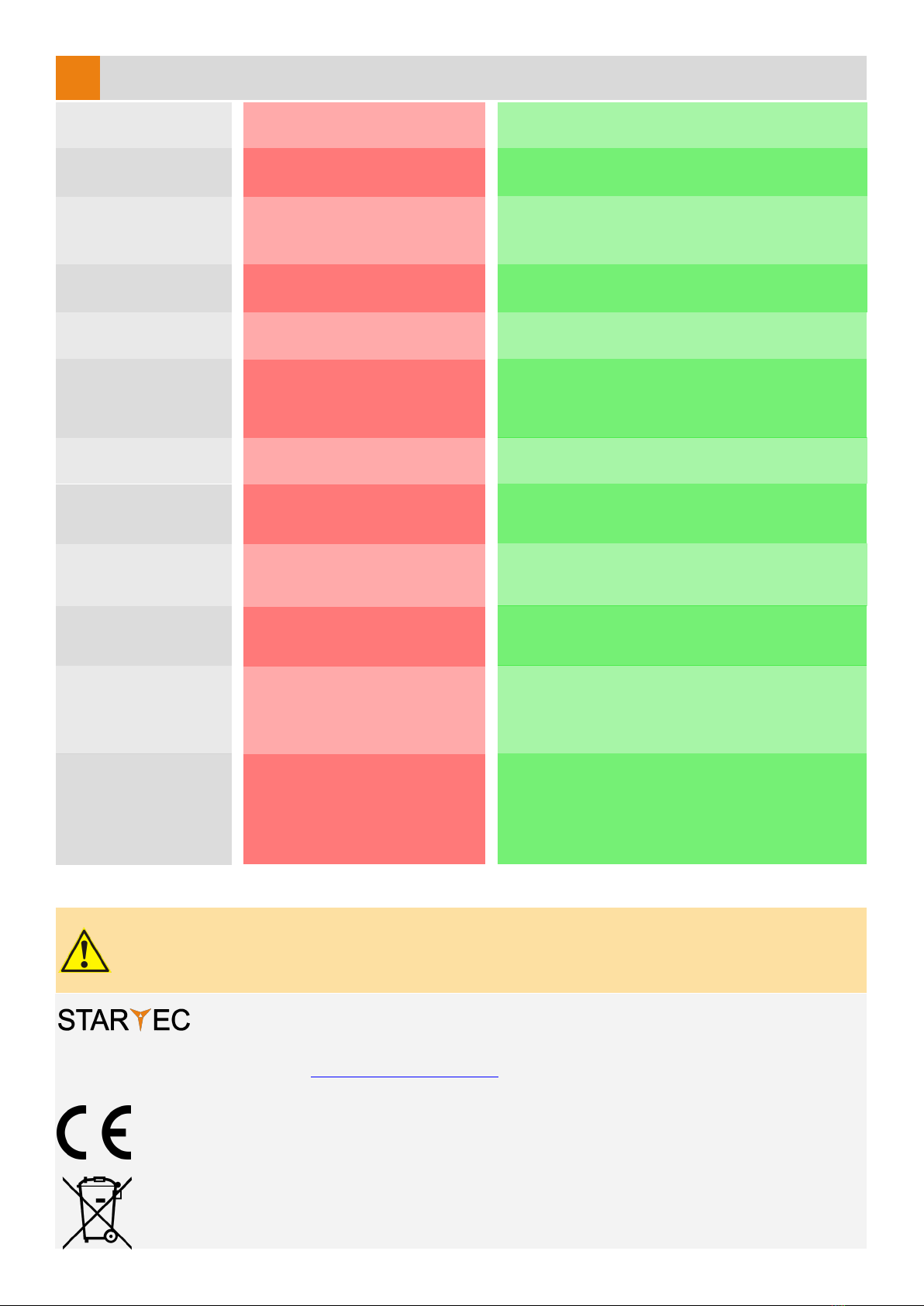
COMMON PROBLEMS
12
The sensor power is off.
The door remains
closed. The LED is OFF.
Check the wiring and the power supply.
Improper output configuration
on the sensor.
The door does not react
as expected.
Check the output configuration setting on each
sensor connected to the door operator.
The sensor is disturbed by the
door motion or vibrations caused
by the door motion.
The door opens and
closes constantly.
1. Make sure the sensor is fixed properly.
2. Increase the tilt/inclination angle.
3. Reduce the field size.
The sensor detects raindrops or
vibrations.
The door opens for no
apparent reason.
1. Decrease sensitivity.
2. Enable vibrations suppression.
SAFETY INSTRUCTIONS
The manufacturer of the door system is responsible for carrying out a risk assessment and installing the sensor and the door system in
compliance with applicable national and international regulations and standards on door safety.
Only trained and qualified personnel may install and setup the sensor.
Only authorised personnel may carry out modifications or repairs to the product. Otherwise the warranty is void.
Improper output configuration
(NO/NC) .
The door stays open. Change the output configuration.
43126 Roncopascolo (Parma)
Via Pescatori Francesco, 5/a
Devices with this symbol must be treated separately during disposal. This must be done in accordance
with the laws of the respective countries for environmentally sound disposal, processing and recycling of
electrical and electronic equipment.
Tel. (0039) 0521 63 11 01; Fax (0039) 0521 63 11 02
www.startec-automazioni.it
info@startec-automazioni.it
STARTEC hereby declares that the CAPTURE is in conformity with the basic requirements and the other
relevant provisions of the directives 2014/53/UE and 2011/65/UE.
Wrong mounting height set.
The door does not
distinguish correctly
between people and
vehicles.
Change the mounting height value.
The clock is not synchronised.
Wrong clock time Connect the smartphone app to the radar to
synchronize the time.
The battery level is low. Replace the battery.
Date and time haven’t been
synchronized with the
smartphone app.
The calendar scheduler
doesn’t work.
The clock always resets
when power is turned
off.
Connect the smartphone app to the radar to
synchronize the time.
Daylight saving time is set to
work properly in the european
countries.
Daylight saving time
(DST) shift doesn’t
work.
Set the calendar scheduler taking into account the
time difference shift of your contry compared to
Central Europe.
The installation type was not se-
lected correcly.
Cross traffic doesn't
work on a corner
installation.
Connect to the radar via the smartphone app and
check the calibration tab. On this page you should
select the installation type (central, corner left,
corner right).
The default configuration has
been changed.
The door opens during
raining or snowing.
Three settings can solve the problem:
1. Set direction detection to "approaching";
2. Disable the first meter of the detection field;
3. Reduce the sensitivity treshold.
This manual suits for next models
4
Table of contents
Popular Radar manuals by other brands

Endress+Hauser
Endress+Hauser Levelflex FMP53 FOUNDATION Fieldbus operating instructions

Blackbe;rry
Blackbe;rry Radar R2 installation guide

Vaisala
Vaisala IRIS user guide

Endress+Hauser
Endress+Hauser Micropilot M FMR245 operating instructions

Furun
Furun FAR-2827 FAR-2127 Operator's manual

Ohmart Vega
Ohmart Vega VEGAPULS 67 Product information


