'"-'
••
.....,
V\,...
\.J
''
t
'·JI'-"
"
~.I
"
"'"'•<...I
" I
(
®
EBL
cm:IDJ
\/. 6 >
By
holding
the
EBL
key
depressed
until
the buzzer sounds, the
"EBL" characters
will
be
displayed
as
reversed character. I
EBL
I
Dy
pressing the
\/
or 6
key,
the
EBL
bearing
line
is
rotated.
U the
EBL
key
i.s
depressed
again,
the
EBL
display
turns "OFF".
The
EBL
position
in
degrees
is
displayed
on
the
CRT
left
top
side
after the "EBL" characters.
®
SEAGUARD
ALARM
(~\/I
6)
By
holding
the I
ALM
I
key
depressed
until
the buzzer sounds, the
reversed
"ALM"
·Characters are
displayed
on
the
CRT.
I
ALM]
By
pressing the
\/
or 6
key,
the
ALARM
range
can
be
varied.
If
the
ALM
key
depressed
again,
the
ALARM
function
turns
OFF.
While
the
alarm
function
is
Off,
"ALM"
range characters are
not
dis-
played.
@
BRILLIANCE
<rIDillJ
\/I
6)
By
depressing
the
BRIL
key,
the brightness
of
the screen
and
the
panel
illumination
can
be
varied
in
intensity.
When
holding
this
key
continuously
until
a buzzer sounds, the
brilliance
will
be
at its
minf-
mum
level. The next
brilliance
step returns the intensity
to
the
lowest level
for
nighttime use.
@ lSHMl
While
the I
SHM
l
key
is
depressed, the
SHM
will
not
be
displayed
on
the screen. This feature
allows
a
small
target under the ships
heading
mark
to
be
seen.
When
the
key
is
released, the
SHM
reappears.
@ I
SELECT
land~
The I
SELECT
l
key
is
used
to
select
one
of
the
following
functions:
·~
l.
Fixed
Rings
ON
or
OFF
2.
Interference
Rejection
ON
or
OFF
(on
screen
indication)
3.
Expansion
ON
or
OFF
(on
screen
indication)
4.
Hold
freezes
display
while
"set"
key
is
depressed
5.
Loran
C Latitude/Longitude
ON
or
OFF
6.
Time
differences
ON
or
OFF
As
the SELECT
key
is
pressed, the reversed character
of
"F", "I",
"E", "H", "L", or "T"
is
displayed
in
the
top
right
when
each
function
is
selected
by
SELECT
key,
the I
SET
I
key
turns the feature
ON
or
OFF
alternatively.
While
"IR"
is
ON,
the "IR" characters are displayed
on
the screen.
While
"EXP" or
"HOLD"
is
ON,
"EXP" or
"HLD"
is
displayed.
When
"L"
or "1"'
is
ON
the
characters appear
at
display
window
below
the
target
video.
3 - 4
,(
(
3.1.3
A
Typical
Operation Procedure
1) Press the f
STBY
/OFF
I
key.
2)
Arter the
sign
on
screen
has
changed
from
"RW"
to
"READY"
(approximately 90 seconds). press the
IX-MIT/OFF
l
key.
3) Set I
BIULLIANCE
Iso
as
to
obtain desired brightness
of
the screen.
IBRILI
4)
Set
the~,
1-{AN~G_,.E,..,lto
the
4,
8,
16
mile
range.
Example:
I
RANGE
16
5)
Check
the
EXP,
JR,
RAIN
CL
and
SEA
CL
modes
are "off'.
6)
Set the l
GAIN
I
to
produce a
light
(noise) background speckle
on
the
screen.
Example:
I
GAIN
I6
7)
Set the
Tuning
control
for
maximum
echoes
on
the screen.
Example:
I
TUNE
I.
\/
or 6 as necessary.
8)
Set the I
RANGE
lscale
you
wish
to
cover.
Example:
l
IMNGE
I
9)
Set the
Rain
clutter
if
necessary;
Sea
clutter
as
necessary.
Example:
I
RAIN
CL
16
I
SEA
CL
I
\/
10)
U necessary, set
IR
to
On
to
reduce radar interference.
Example:
Press I
SELECT!,
OJ,
press I
SET
I
11)
For range
and
bearing measurements, set
EBL
and
Vl{M
to
On.
12)
When
the radar
is
no
longer required, depress
the
I
STBY/Ol'F
I
and
IX-MIT/OFF
I
key
together at the same
time.
The
radar
will
be
"OF!-'".
If
you
wish
to
keep the radar
in
a state
of
immediate readi-
ness, press
only
the I
STBYIOFF
l
key.
The screen
will
indicate
"STANDBY"
condition.
3.2
RANGE
AND
BEARING
MEASUREMENT
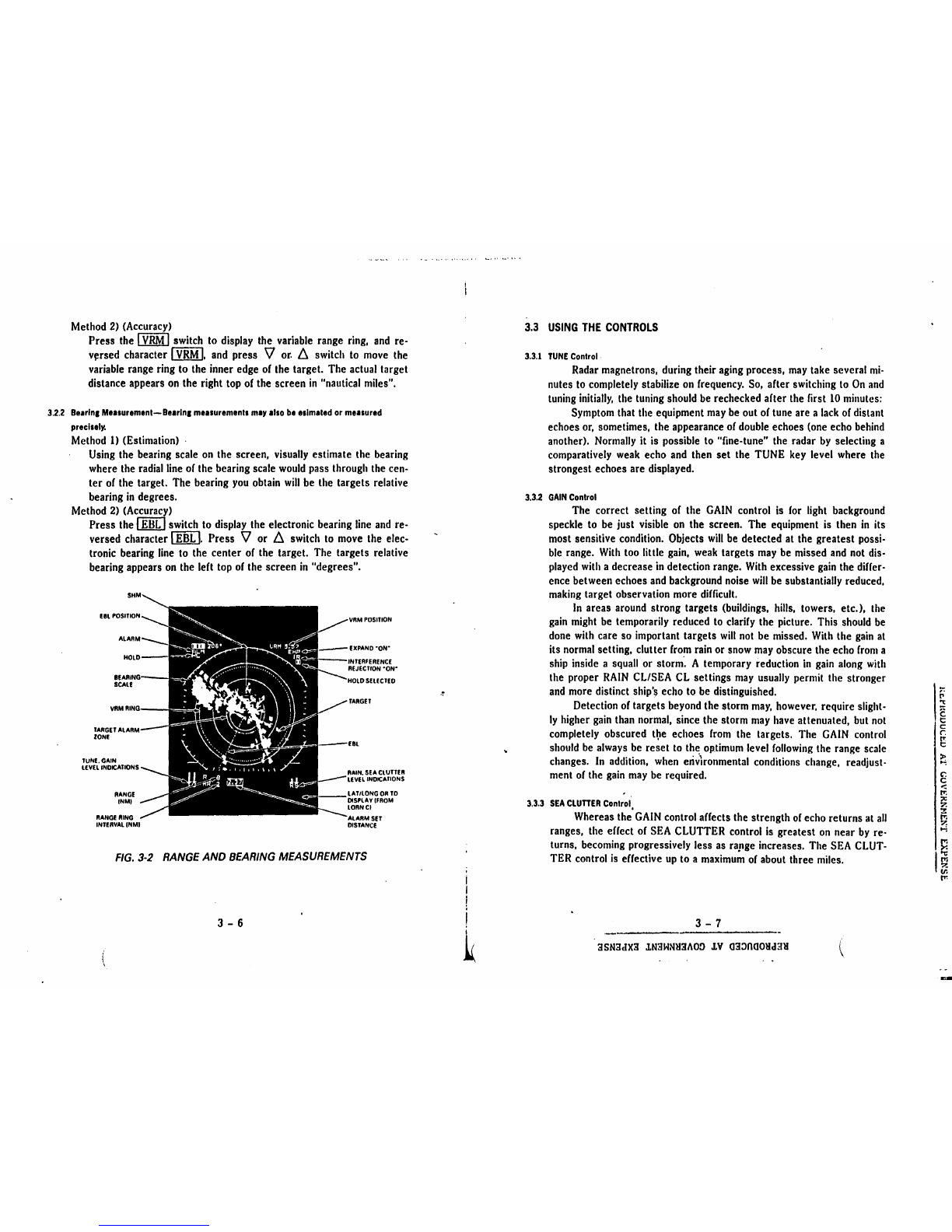
(See
Fig.
3·2.)
The picture
on
the screen shows a
view
of
the
position
of
targets
around
your
vessel.
In
effect
your
ship
is
at
the center
of
the
screen
and
targets arc presented
in
polar
coordinates (or
map-like)
throughout
360
degrees.
Your
vessel
is
alwa_y&
~heading"
at
"O"
degrees. The
display
is
referred
to
as
the
PPI
(Plan
P~si!ion
Indicator).
3.2.1
Ranae
Measurement-Ranae measurements
to
tar1ets
may
be
made
by
estimation
or
accurally
m111urln1
distances
with
the
VRM.
Method
I)
(Estimation)
Note
the range scale
in
use
and
the distance bet
ween
rings
Count
the number
of
rings between the center
of
the screen
and
the target,
and
visually
estimate the distance bet
ween
the inner edge
of
the target
and
inner edge
of
the nearest
ring.
..
a..::.?.
____
.··--·
'.'JSNilrlX3
lNilHNH'.MO:J
.J.V
O:t:l000llr13M
'1
:-:
I':
't:
lg
i~
' !;
)>:
...,
8
<
I':
I
·~
~
t-l
It'1
:
><
1
0-.:
rr.
!~
v.
t"
-