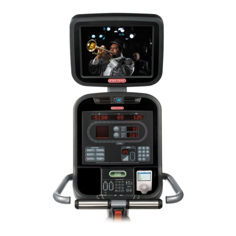
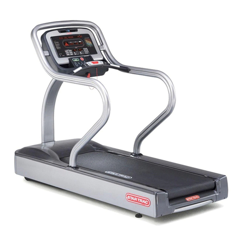
Star Trac PVS Series User manual

Troubleshooting
STAR TRAC FITNESS 1 of 1 637-1401 Rev: A
PVS Troubleshooting Guide
All PVS Kits
This guide contains troubleshooting information on PVS kits for symptoms such as:
•Poor Picture Quality on a PVS Screen
•Screen Will Not Power Up (treadmills)

Make sure the
treadmill is turned
on.
Is the treadmill
on?
Verify that the
treadmill plugged
into the wall and
the power switch is
set to the ‘on’
position?
Unit plugged in and
power switch on?
Plug the treadmill
into the wall outlet
and turn the power
switch to the ‘on’
position.
No
Does the
treadmill turn
on?
Yes
No
The issue is with the
treadmill and not the
PVS. Troubleshoot the
treadmill.
No
Cycle the power to the
treadmill off, then turn
back on. After 20
seconds the screen
should turn on.
Yes
Did the screen
turn on?
The screen is
operational. Yes
Press the power
button on the
entertainment
console.
No Did the screen
turn on?
Yes
The next step will
require the use
and external
power supply.
No
Using an External
Power Supply for
PVS Screens
(637-1400)
Yes
Did the screen
turn on?
Replace the screen and
return failed screen to
Star Trac. No Is external
power supply
available?
Yes
Without an external
power supply, multiple
checks will need to be
made. Follow
procedures in
“Checking the Power
Supply and Power
Cables”.
No
The screen is good. Multiple
checks will need to be made to
determine the root cause. Follow
the procedures outlined in
“Checking the Power Supply and
Power Cables”
Checking the
Power Supply and
Power Cables
(637-1381)
The screen is
operational.
Checking the
Power Supply and
Power Cables
(637-1381)
Did the screen
turn on?
Replace the screen and
return failed screen to
Star Trac.
The screen is
operational.
Yes
No
PVS Screen Won’t Power Up (Treadmills)

Is there more than
one machine with
a PVS kit?
More than 1
PVS?
Tune other screens to
the same channel to
see if they have the
same poor quality
picture.
Yes All have same
quality picture?
Issue is with the
feed** and not the
PVS
Yes
Make sure the coax cable is firmly connected
to the wall outlet and the bottom of the unit.
Also check the internal coax cable in the unit.
Make sure it’s firmly attached to both
couplers.
No No
Coax is firmly
connected?
Tighten the connections of
the coax cable. Tighten
both the external and
internal coax cable
connectionsin the unit.
No Did picture
quality
improve? Issue is resolved.Yes
Bypass the coax
cable in the unit.
Bypassing
the Coax
Cable in the
Unit
(637-1398)
No
Yes
Poor Picture Quality on a PVS Screen
Determine the
screen type.
Determining
the Screen
Type
(637-1397)
UTI or Tatung?
UTI
For Tatung
screens, reset the
software in the
screen.
Tatung
Poor Screen
Color with Poor
Picture Quality
(637-1389)
Did picture
quality
improve? No
Issue is resolved.
Yes
Did picture
quality
improve?
Yes
No
If available, find a
nearby unit with
good picture
quality.
Is a nearby unit
available?
Yes
Swap coax cables
between suspect
and good unit.
Use a Known
Good Coax
Cable Source
(637-1399)
Replace the coax
cable inside the unit.
Replace the PVS screen
and return the failed
screen back to Star Trac.
Screen A = Poor
Screen B = Good
Result 1
Screen A still has
poor quality and
screen B has good
quality.
Yes
Result 2
Screen A has
good quality but
screen B has poor
quality.
No
The PVS screen is good.
Replace the coax cable.
It’s possible that the coax
cable from the wall to the
unit is the cause.
Did the picture
quality improve?
Issue is with the
feed** and not the
PVS
No
Issue is resolved.
Yes
Find another TV or
screen to test the
feed from the wall.
No
Is 2nd TV
picture quality
good?
Yes
No
** Consult with your facility’s Audio/Visual expert or your cable/ satellite provider.

Troubleshooting
STAR TRAC FITNESS 1 of 2 637-1400 Rev: A
Test a PVS Screen with an External Power Supply
All PVS Screens
When troubleshooting a PVS screen that won’t power up, using an external 12 VDC power supply is the fastest way to
determine if the screen is working. The following procedure explains how to use the external power supply.
Use an External Power Supply
Use a separate 12 volt DC power supply (Fig. 1). The power supply from the E Series bikes, or TBT’s that have PVS will
work as well.
Fig. 1
1. Remove the back housing of the screen (Fig. 2) and disconnect the input AC power (Fig. 3).
Fig. 2
Fig. 3

Troubleshooting
STAR TRAC FITNESS 2 of 2 637-1400 Rev: A
2. Insert the external power supply into the back of the screen (Fig. 4) and plug it into the wall (Fig. 5).
Fig. 4
Fig. 5

Troubleshooting
STAR TRAC FITNESS 1 of 7 637-1381 Rev: B
Checking the Power Supply and Power Cables
E Series Treadmills
This document contains troubleshooting for both Version 1 and Version 2 MCB’s.
These procedures will require the motor shroud to be removed.
Warning: The following procedures require the power to be on. Take
extreme caution when working around live electrical components.
Version 1 MCB
If an embedded treadmill display will not power up, yet there appears to be power on the power supply, follow the steps
outlined in this document.
Tools Needed:
•Phillips screwdriver
•Multi-meter
•Small flathead screwdriver
Note: The procedures in this troubleshooting document require the power to be on and the drive motor shroud to be
removed. Take extreme caution when working around live electronic components.

Troubleshooting
STAR TRAC FITNESS 2 of 7 637-1381 Rev: B
Check the Power Supply
1. Check the power supply to see if the LED is lit (Fig. 1).
•If the LED is off, refer to document Checking the Power Supply (doc number: 637-1379) for
troubleshooting instructions.
•If the LED is on, continue on to step 2.
Fig. 1
2. Visually inspect the power cable connection at the power supply. Check for burned or charred marks on the
plastic connector (Fig. 2).
Fig. 2
•If there are burn marks on the connector, the cable must be replaced.
•If there are no burn marks on the connector, go to step 3.
Warning: The following procedures require the power to be on. Take
extreme caution when working around live electrical components.
3. Set the multi-meter to read DC voltage and take a reading between pins 1 (white) and 3 (black) (Fig. 3).The leads
must be in contact with the pin in the plastic connector to get a proper reading. There should be approximately 12
volts DC.

Troubleshooting
STAR TRAC FITNESS 3 of 7 637-1381 Rev: B
Fig. 3
•If there is no voltage, replace the power supply.
•If there is 12 volts, continue to Check the Connector at Screen or PVS CCB
Check the Connector at the Screen or PVS CCB
1. Visually inspect the power cable connection at the embedded screen/PVS CCB. Check for burned or charred
marks on the plastic connector (Fig. 4).
Fig. 4
•If there are burn marks on the connector, the cable must be replaced.
•If there are no burns on the connector, continue to Verify Voltage to the Screen or PVS CCB

Troubleshooting
STAR TRAC FITNESS 4 of 7 637-1381 Rev: B
Verify Voltage to the Screen or PVS CCB
1. Set the multi-meter to read DC voltage. Insert the leads into the plastic connector (Fig. 5 and 6). The leads must
be in contact with the pin in the plastic connector to get a proper reading. There should be at least 11 VDC.
Embedded Screen
Fig. 5
CCB
Fig. 6
•If the voltage is less than 10.4 volts DC, replace the power cable.
•If the voltage is between 10.5 and 10.9 volts leave the multi-meter leads in the plastic connector and continue
to Adjusting the Power Supply Potentiometer
•If the voltage is greater than 11 VDC, the power supply is sufficient.
Adjusting the Power Supply Potentiometer
1. Locate the potentiometer (pot) on the power supply (Fig. 6).
Fig. 6
2. Using the small flathead screwdriver, make small adjustments in the counter-clockwise direction and watch the
multi-meter. Turn the pot till the meter reads 11.2 volts.

Troubleshooting
STAR TRAC FITNESS 5 of 7 637-1381 Rev: B
Version 2 MCB
1. Visually inspect the power cable connection at the MCB (Fig. 7). Check for burned or charred marks on the plastic
connector (Fig. 8).
Fig. 7
Fig. 8
•If there are burn marks on the connector, the cable must be replaced.
•If there are no burn marks on the connector, go Check the Connector at the Screen or PVS CCB
Check the Connector at the Screen or PVS CCB
1. Visually inspect the power cable connection at the embedded screen/PVS CCB. Check for burned or charred
marks on the plastic connector (Fig. 4).
Fig. 4
•If there are burn marks on the connector, the cable must be replaced.
•If there are no burns on the connector, continue to ‘Checking Power at the MCB’

Troubleshooting
STAR TRAC FITNESS 6 of 7 637-1381 Rev: B
Warning: The following procedures require the power to be on. Take
extreme caution when working around live electrical components.
Check Power at the MCB
1. Set the multi-meter to read DC voltage and take a reading between white and black wires (Fig. 9). The leads must
be in contact with the pin in the plastic connector to get a proper reading. There should be approximately 12 volts
DC.
Fig. 9
•If there is no voltage, and the diagnostic LED’s are lit, replace the MCB.
•If there is voltage, continue on to Verify Voltage to the Screen or PVS CCB.

Troubleshooting
STAR TRAC FITNESS 7 of 7 637-1381 Rev: B
Warning: The following procedures require the power to be on. Take
extreme caution when working around live electrical components.
Verify Voltage to the Screen or PVS CCB
1. Set the multi-meter to read DC voltage. Insert the leads into the plastic connector (Fig. 10 and 11). The leads
must be in contact with the pin in the plastic connector to get a proper reading. There should be at least 11 VDC.
Embedded Screen
Fig. 10
CCB
Fig. 11
•If the voltage is below 11 VDC, replace the power cable.
•If the voltage is greater than 11 VDC, the power supply is sufficient.

Troubleshooting
STAR TRAC FITNESS 1 of 1 637-1397 Rev: A
Determining the PVS Screen Type
PVS Screens
There are times that it is important to know the type of screen in order to properly troubleshoot an issue.
The following document will explain how to determine which of the two screens types.
The two types are:
•UTI
•Tatung
To determine the screen type, remove the plastic back cover of the screen and look for the label.
UTI
UTI screens will have the label on the upper right corner of the screen (Fig. 1 and 2).
.
Fig. 1
Fig. 2
Tatung
Tatung screens will have the label towards the left center of the screen (Fig. 3 and 4)
Fig. 3
Fig. 4

Troubleshooting
STAR TRAC FITNESS 1 of 5 637-1389 Rev: A
Poor Screen Color with Poor Picture Quality
PVS Part Numbers: 700-0138 & 700-0140
Star Trac has received some reports where the Personal Viewing Screen (PVS) color changes to one tone and the picture
quality becomes poor. To resolve this issue, a total reset of the screens firmware is required.
The following instructions explain the process to retting the firmware.
Resetting the Screen
1. Turn on the screen and enter the screen menus (Fig. 1), by pressing volume , channel , and .
Fig.1

Troubleshooting
STAR TRAC FITNESS 2 of 5 637-1389 Rev: A
2. Enter the factory mode by quickly pressing the code ‘2580’. If the screen does not go into the factory mode, try
again until a small menu will be displayed in the upper left hand corner of the screen (Fig. 2).
Fig. 2
3. Press CH/TRK once to reach the setting ‘Function’ (Fig. 3).
Fig. 3

Troubleshooting
STAR TRAC FITNESS 3 of 5 637-1389 Rev: A
4. Press VOL once to reach the sub-menu ‘Aging Mode’ (Fig. 4).
Fig. 4
5. Press CH/TRK 3 times to reach to ‘Reset All’ (Fig. 5).
Fig. 5

Troubleshooting
STAR TRAC FITNESS 4 of 5 637-1389 Rev: A
6. Press VOL once to reach the sub-menu ‘On / Off’ (Fig. 6).
Fig. 6
7. Press CH/TRK once to select ‘On’ (Fig. 7).
Fig. 7

Troubleshooting
STAR TRAC FITNESS 5 of 5 637-1389 Rev: A
8. Press once to reset the screen. The screen will turn black for a few seconds now.
9. The set up wizard will come up for you to enter your preferences (Fig. 8).
Fig. 8)
10. After you have set up your preferences you need to perform a channel scan in order to see all available channels.
11. Check the screen if it operates properly again and if this did resolve the original issue.

Troubleshooting
STAR TRAC FITNESS 1 of 2 637-1398 Rev: A
Bypassing A Product’s PVS Coax Cable
All Cardio Products with PVS Kits
When troubleshooting a PVS issue such as:
•Poor Picture Quality;
•Some channels missing after channel scan;
•No channels found after channel scan;
Bypassing the coax cable inside the cardio machine may be necessary. This is for troubleshooting purposes only.
1. Remove the back housing of the screen (Fig. 1)
Fig.1
2. Disconnect the coax cable going into the screen (Fig. 2) and disconnect the coax cable going into the bottom of
the treadmill (Fig. 3).
Fig. 2
Fig. 3

Troubleshooting
STAR TRAC FITNESS 2 of 2 637-1398 Rev: A
3. Connect the coax cable from the wall directly into the back of the screen (Fig. 4).
Fig. 4
This manual suits for next models
2
Table of contents
Other Star Trac Monitor manuals
